
Introduction
Nove Mesto
Everything began with my studio project, I have chosen an assignment that requires me to work carefully with a very steep slope. It is in Nove Mesto nad Metuji, it is the south-west side of the historic town (where the castle is).
You can watch this video where I try to explain some of what follows (but keep reading too!): https://youtu.be/5c1w6Sq7fKk
Big data
To get a sight or to fully discover and to understand the terrain, I remembered there is geoportal.cuzk.cz, but it was my first experience working with the site. All I needed was to convert an .shp file to a Rhino friendly format. After some digging online I found the CloudCompare software. It is free, quite compact and pretty intuitive (as opposed to ArcGIS, that makes you download 30 GB, is paid and very difficult to navigate in for a newbie like me).
So here I was with a pointcloud of the town and I could feed it to Rhino to try and create a 3D model of the terrain.
Meshes
Mesh trouble
Let’s show a few steps from Rhino and Grasshopper before we move forward.
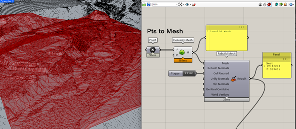
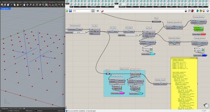
This is a basic script that converts a collection of points that I selected to a mesh (all the black dots are points of the pointcloud – 608610 points; for the mesh, I use around 44 000 points), a shape I further use in my studio (but smaller).
Notice that Delaunay Mesh component produces a mesh that is Invalid – this can be fixed with Rebuild Mesh from the Pufferfish plugin. But I wanted to know more about the invalidity and I started digging deeper… Let’s bake the invalid mesh.
Why invalid?
After baking the mesh, I selected it and ran the Check command in Rhino. A pop-up window with the following text appeared:
General information about this mesh:
Mesh has 4 degenerate faces.
Mesh has 4 non manifold edges.
Skipping face direction check because of positive non manifold edge count.
Mesh has 61 naked edges. Naked edges can cause problems if the ultimate goal is STL output.
Mesh has 50 faces where the face normal differs substantially from the vertex normals.
These normals can cause problems if the ultimate goal is for rendering or boolean purposes.
Mesh does not have any n-gons.
Mesh does not have any extremely short edges.
Mesh does not have any duplicate faces.
Mesh does not have any self intersecting faces.
Mesh does not have any disjoint pieces.
Mesh does not have any unused vertices.
ID: b89cef6b-d393-4d16-a62f-c02e2e952751 (665681)
Object name: Mesh: ON_Mesh.m_F[394] has degenerate double precision vertex locations.
Layer name: pointscloud
Render Material:
source = from layer
index = -1
Attribute UserData:
UserData ID: ___
Plug-in: 17b3ecda-17ba-4e45-9e67-a2b8d9be520d
description: User text (1 entries)
saved in file: yes
copy count: 2
Geometry:
Invalid mesh.
Open double precision polygon mesh: 46214 vertices, 92365 faces with normals
Bounding box: (-617174,-1.03059e+06,286.41) to (-616250,-1.02997e+06,346.19)
Geometry UserData:
UserData ID: __
description:
saved in file: no
copy count: 0
The most important for me (and this paper) is the first paragraph – degenerate face and non-manifold edge. I knew I had heard it somewhere before and I have decided to find out what it is!
Mesh components
Polygon mesh consists of vertices, edges and faces. There are several types of edges regarding meshes:
naked or interior edges – naked edges create a boundary of the mesh, in other words every naked edge is only adjacent to one face.
manifold or non-manifold edges – manifoldness can be said about a mesh, there are two conditions for a mesh to be manifold: each edge is incident to only one (naked e.) or two (interior e.) faces AND the faces incident to a vertex form a closed or an open fan (look for Fan triangulation or Triangle fan). Therefore, manifold edge is incident to one or two faces and every other edge is non-manifold.
This means that every interior edge is manifold, it should be true about naked edge too, but I am not sure if a naked edge of a degenerate face (its area is zero or negative) can be considered as manifold… (I guess the same could be said about two degenerate faces sharing an interior edge…)
(Non)Manifold?
So when I return to the Check command, what both Rhino and Grasshopper tried to tell me was that manifold mesh is valid or correct and non-manifold mesh is invalid and wrong? Usually non-manifold meshes (edges) mean trouble but there is a method that makes use of non-manifold modelling.
It is called Topologic, it is “an open-source software modelling library enabling hierarchical and topological representations of architectural spaces, buildings and artefacts through non-manifold topology (NMT).” (https://topologic.app/)
For our use you can install it as a plugin to you Rhino&Grasshopper. There is a set of tutorials on the page as well as some introduction to the theory of topology, quite a wide discipline of its own.
I am going to briefly introduce some terms you may encounter, so things may get a bit boring now.
Topology
Glossary
Topology studies geometry objects, but more than mesurable values, it is concerned of relations in space, ‘topological space’ – in topology a circle and a square are equivalent but a circle curve and line are very different.
There is a class hierarchy as on the picture below, I will explain the terms now.
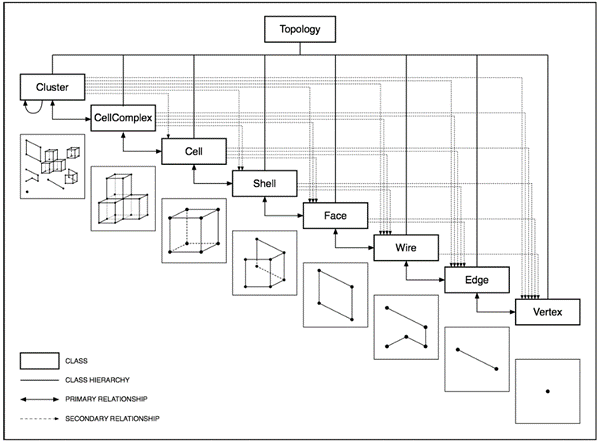
Topology: any/all geometry
Cluster: contains any geometries listed below, any combination of data
CellComplex: is a set of cells that share faces with each other
Cell: is a 3D closed geometry, it consists of one or more shells (closed polysurface)
Shell: one or multiple faces connected by edges (open polysurface)
Face: 2D region bounded by closed wires (surface)
Wire: edges connected in vertices (polyline)
Edge: connection of two vertices (line)
Vertex: is a point
Aside from these geometries there are other terms you can work with. I cannot explain all of them as I am not a topology expert, but I picked up something when I was experimenting with the plugin.
Dictionary and Keys: this allows you to create categories (dictionaries) defined by their name (key); in practice, let’s say you have topologic representation of a building, you set dictionaries to rooms according to their purpose (living room, bedroom, office, toilet) and that will later allow you to analyze all of these spaces separately, compare their qualities (area, volume, positioning) but even with other plugins like Ladybug or HoneyBee
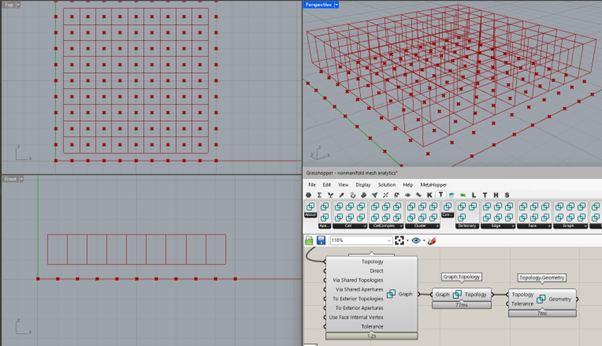
Graph: this is a thick theme in topology, I think that all the tutorials are working with ‘geometric graph’, that is basically vertices and edges; in the tutorial number 6 (picture below), there is a CellComplex and is fed directly into a Graph component, it produces a set of lines between the centroids of the cells, therefore graphs vertices are the centroids and edges connect centroids of the adjacent cells
With this picture, we can start with the plugin itself.
Topologic
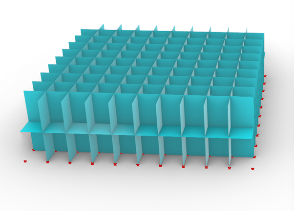
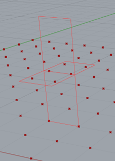
Topologics biggest strength is that it carries a lot of data. For example, every Cell still carries its wires, edges, faces and vertices. I prepared a simple non-manifold mesh structure to demonstrate some stuff of the plugin:
Topologist would say it is a CellComplex with 200 Cells, some Shells, Faces, Wires and so on. (Probably, they could say something completely different.) To me, it could be a representation of a two-storey building, just without specified connection of the spaces. I won’t cover this script.
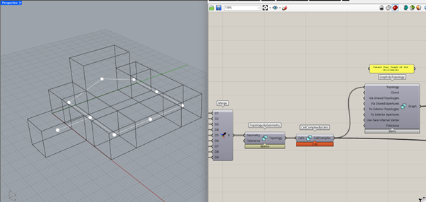
Moving on, we start with Topologic, firstly, you need to convert any geometry you want to analyze to a topology. For that you use Topology.ByGeometry component. It creates a Cluster of separate Cells, but I wanted to create a CellComplex, so I used Cluster.Cells to produce a list of individual Cells and then connected them together to a CellComplex with CellComplex.ByCells.
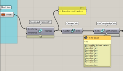
Having a CellComplex allows me to explore and analyze various connections and relationships in it:
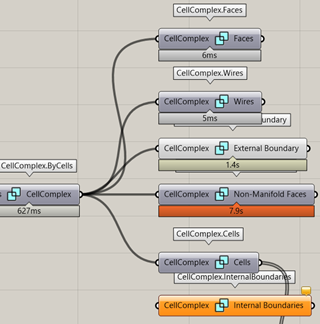
Non-manifold Faces! All faces that are incident to two cells:
Other thing you can try is finding neighbours of geometries:
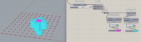
I retrieve the Cells of the CellComplex with CellComplex.Cells, pick a Cell (pink) with List Item and feed it to Cell.AdjancentCells (blue).
By default, Topologic doesn’t preview any geometry (I believe it is for preserving the speed of the computation, two pictures back, you could see that the computation times are quite high), so to see something, you have to use Topology.Geometry. I further add colour with Custom Preview.
Here, the blue group on the bottom is what I just ran through.
I added Topology.Analyze – on a first sight a very attractive component that breaks down the topology of any geometry you feed to it. It runs fine but I had some crashes when I tried to connect the Panel, I believe that the Panel component may have trouble with long texts.
If you trace back to where I started and picked a Cell – List Item, Index 74 – I added a new branch of analysis there Cell.Wires and Wire.Edges – the Cell has 6 wires and each of these wires has 4 edges, thus the list contains 24 edges after Flatten the input stream to List Item. Here I pick an Edge (previewed as light blue in the Rhino viewport) and perform Edge.AdjancentEdges – returns previewed darker blue edges.
You may also notice EdgeUtility.AdjancentWires, the Parent Topology is the CellComplex, here’s what it does:
That gives us insight into what adjacent means for Edges and Wires – for two Edges to be adjacent, it appears to be enough to have one common vertex, but for an Edge and Wire, the Edge must be a segment of the Wire.
To the end of Topologic, I just want to show you what a Graph of my CellComplex looks like. In this wireframe you could try some path finding and so…
This was a preview of the Topologic plugin that can take advantage of non-manifold geometry.
What I learned
Manifoldness
From all the internet I scrolled and read through, I understand that to safely identify a manifold (topological space – imagine it as a surface of some geometry I would say) in the context of mathematics and topology, can be really challenging, also I found these statements quite funny:
“…all manifolds are equal, but some are more equal… “,
„Manifoldness is a black night in which all the cows are black. Recognizing manifold cows is obvious for triangulated meshes (a.k.a. 2-complexes) and tetrahedralization (3-complexes) but recognizing if a n-complex is a manifold, in general, cannot be done for n greather than six (let alone the String Theory…). “ – some smart guy on the Internet, I am barely catching up here.
But once we set aside generalization of maths and topology, it is fairly easy to define what manifold is and the rest is just non-manifold. Earlier I reproduced the two rules:
each edge is incident to only one or two faces
the faces incident to a vertex form a closed or an open fan
Within Rhino context, I was surprised when I created my non-manifold mesh for the Topologic analysis, that it was not invalid. I assumed earlier (the Delaunay Mesh script) that the non-manifold edges were the cause of the invalidity. I learned this way that non-manifold does NOT mean invalid. (Now I assume it was the degenerate face??)
3D printing
Non-manifold geometry is your archenemy in this area, the Internet is full of various advice “How to get rid of non-manifold edge/mesh!”. (This annoyed me a bit because I wanted to make use of it.)
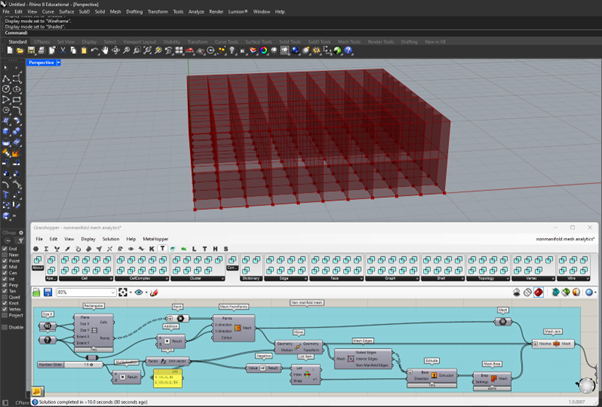
One of definitions I found is that non-manifold geometry does not have thickness somewhere in it, so it is not able to physically exist or to be constructed and solid/rigid.
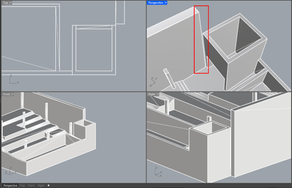
As look on the structure above, focus on the area in the red square. There is a small gap and it is looking a bit odd, but it has an important meaning, this is a model prepared for 3D printing. If the gap was not there, the resulting edge would be non-manifold, because there would be more than 2 faces incident to it – therefore trouble for your 3D printer! So watch out for non-manifold geometry, in my experience, SketchUp likes to produce tons of it in complex models, find a friend with Rhino who can fix stuff! (Especially with the new Rhino8 command ShrinkWrap! I love it.)
Robert Aish, Wassim Jabi
These two are mainly responsible for the Topologic plugin, but not just that. Both have published papers in which they compare BIM and abstract topologic representation of a building or examine energy management and more. (Check those out!)
Last words
I can imagine that Topologic could be very handful when analysing some computer-generated organic structures. I believe it could perform analysis for Space Syntax – analysis in the field of urbanism of cities, originating from graph theory (e.g. betweenness centrality).
However, for an architect, it is challenging to implement all these methods I am mentioning. I don’t exactly know how big architecture or urbanism studios work but I can imagine these analyses could get quite time consuming and require decent number of resources. Another take is that assignments which could benefit from these methods do not, because of lack of knowledge among architects, who just don’t know what everything is available.