
INTRODUCTION
The goal was to design a parametric bench out of a form which can serve as a lounge bench or a chair, depending on the rotation of its elements. Built out of identical wooden elements along a curved steel construction the bench should be rotable and this rotation should be shown in an animation.
INSPIRATION
The inspiration was found in other parametric benches in changing sizes. Through measuring the average human body a form was constructed, that can serve as a sitting chair or a lounge chair.

THE FILE
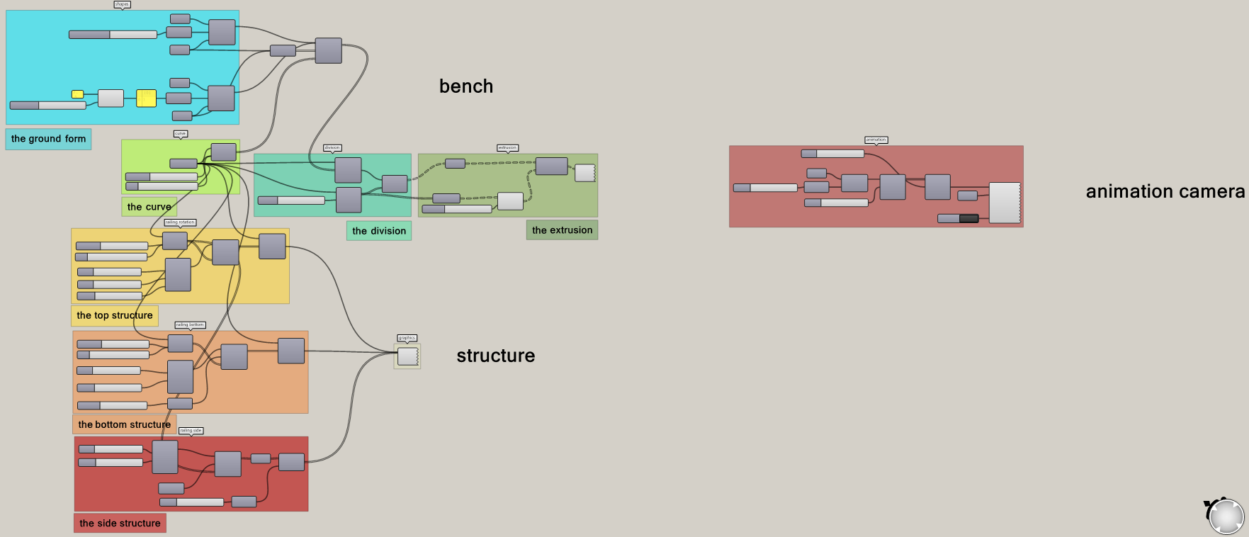
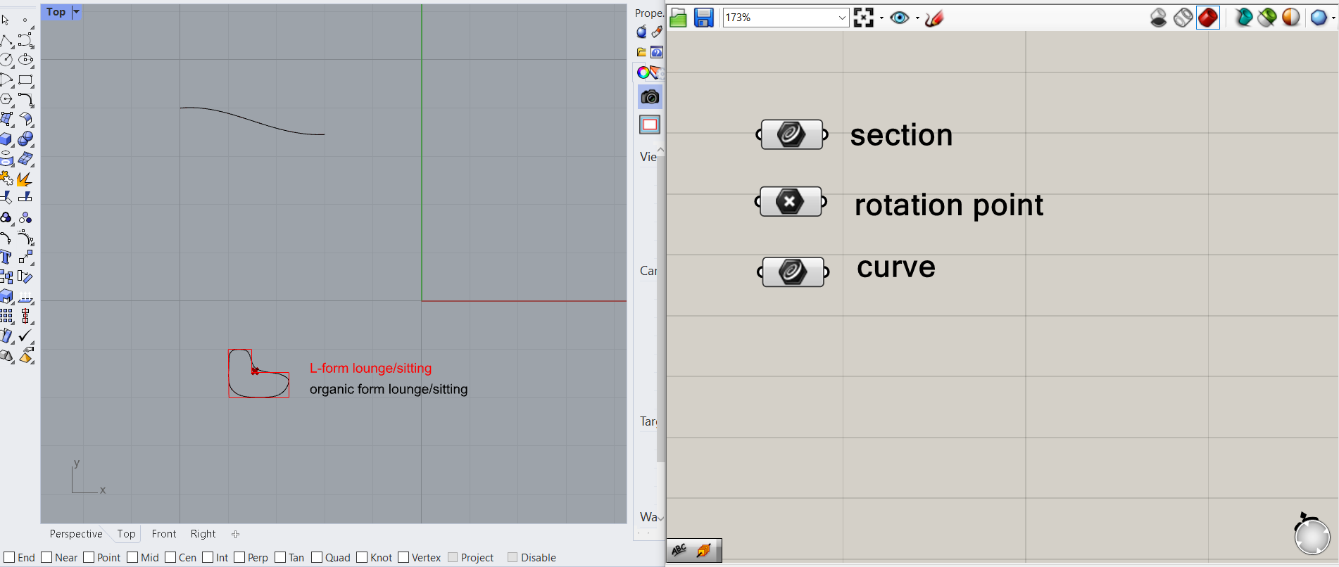
1 I THE PREPARATIONS
To create a bench, consisting of a wooden element which can be used for sitting or lying, I drew this element in Rhino. I created a curve in grasshopper and set this section form in the top view to it. Then, still in the top view, I drew the ground shape in rhino, which I also set as a curve in grasshopper. To later orient the section shape onto that curve I need a point, which will function as a rotation point.
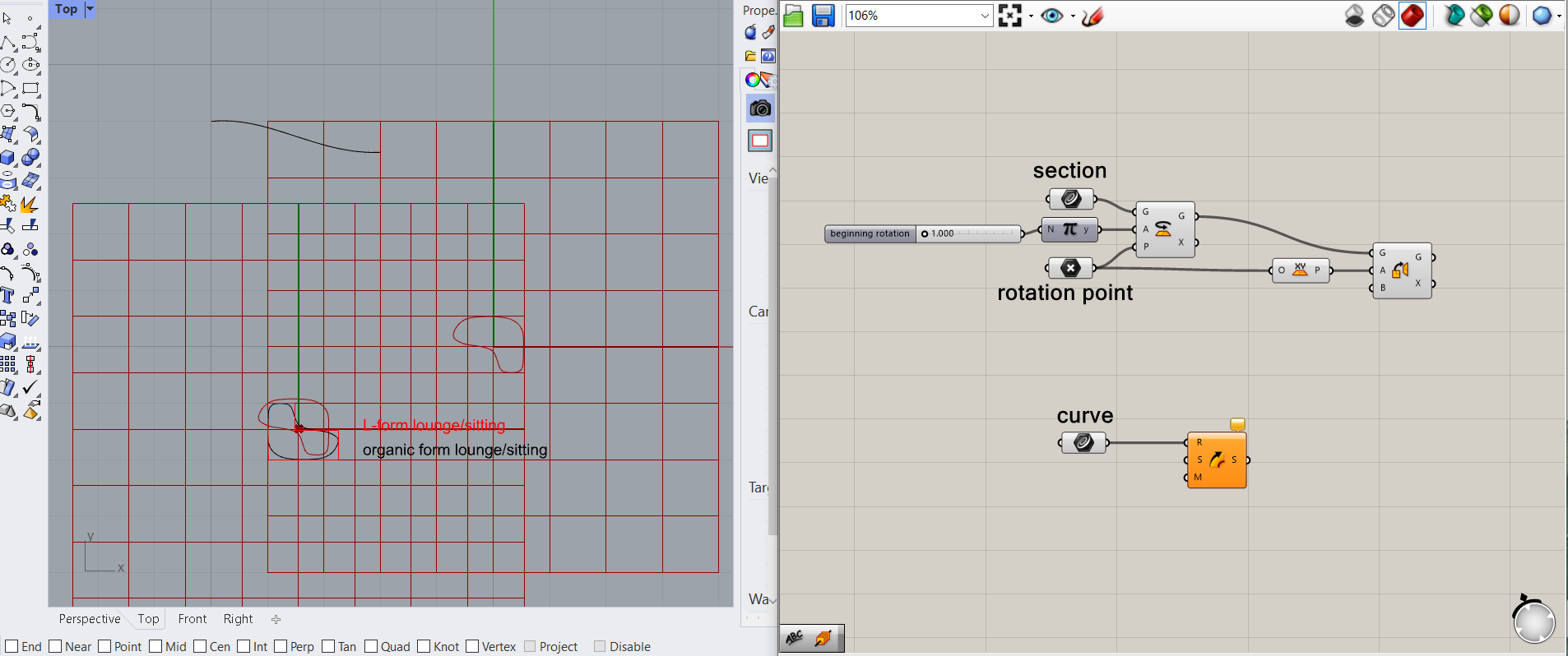
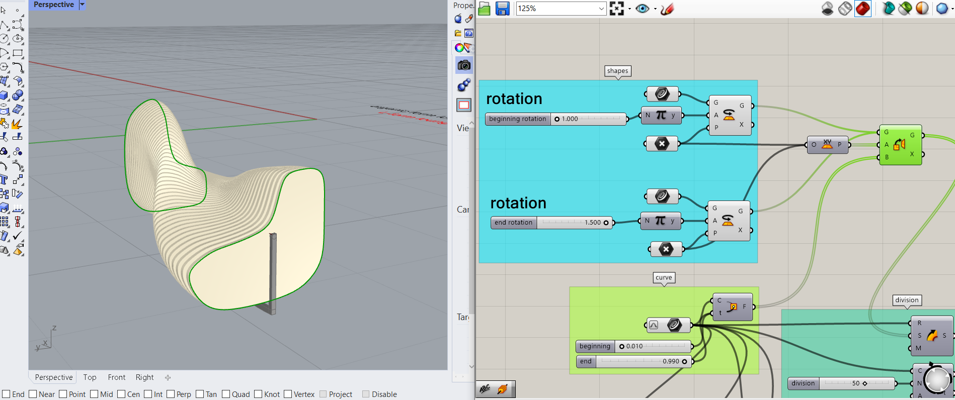
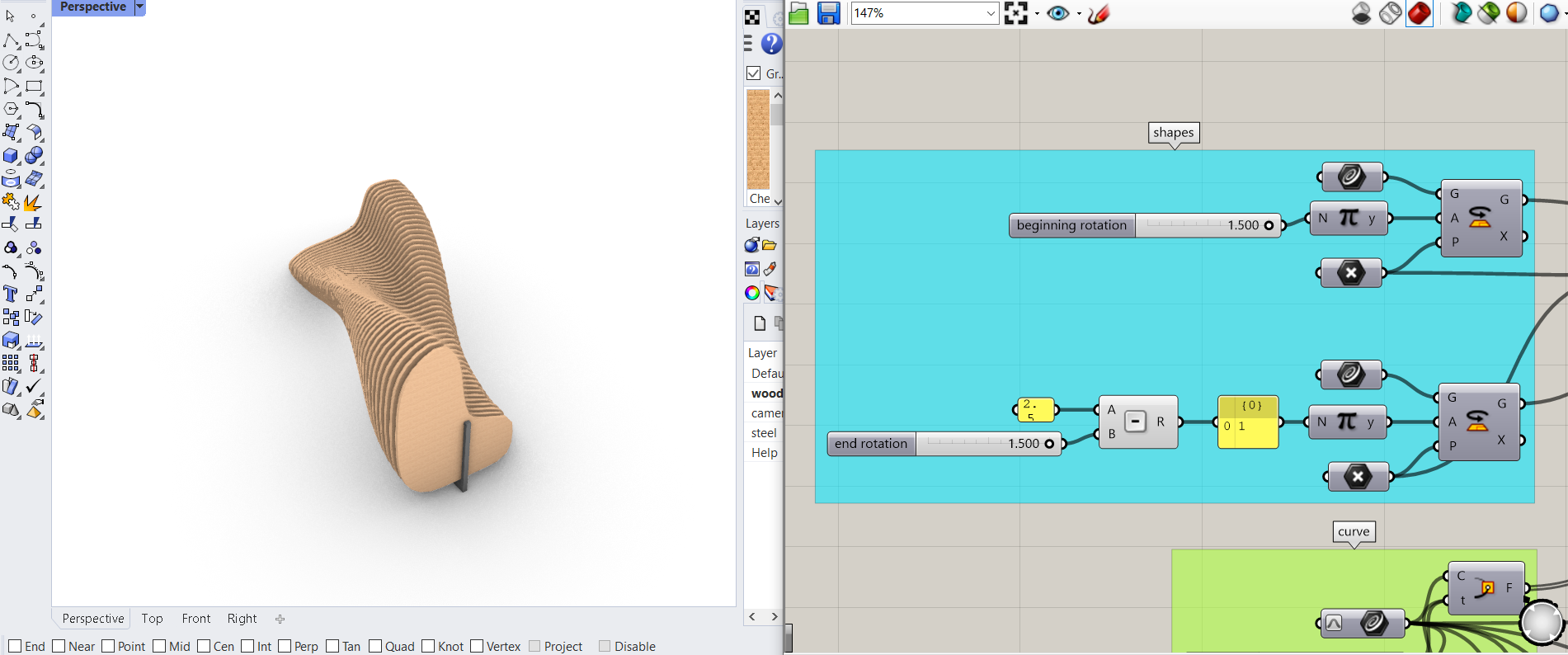
Out of the section shape I want to create two different rotations: The beginning and the end of the bench, one lying and one sitting. Therefore, I rotated the curve with a number slider of 1.00 multiplied with π. The rotation should be around the already set rotation point, so I attached it to the plane input. After rotating the shape, I also want to orient it from the xy-plane onto the ground curve. Also the curve is connected to the curve input of a sweep 1 component to later orient the shape.
2 l THE BENCH
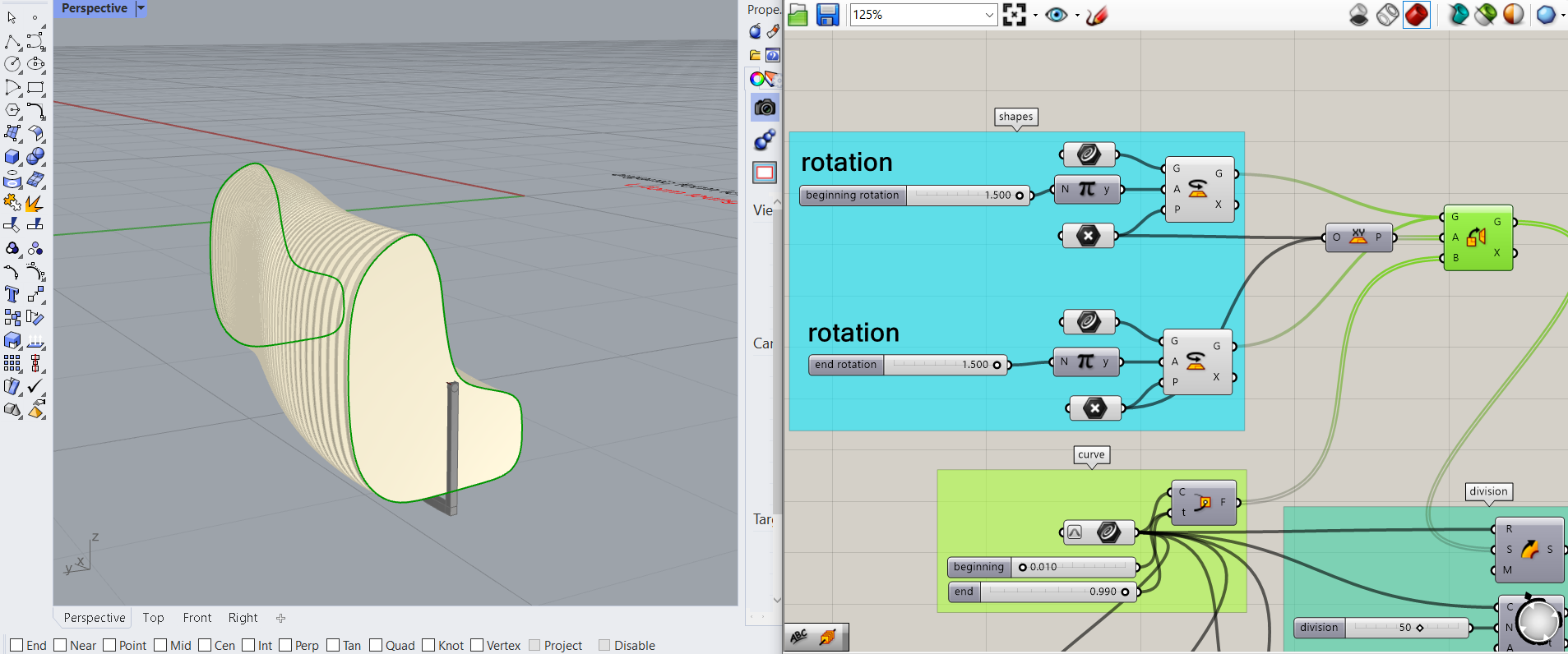
This rotation defines the first frame. To be able to rotate the beginning and the end of the bench differently I copied the rotation with all its connected panels and changed the number slider to 1.5. This are now the two opposite positions, sitting and lounging. Both shapes should be orientated on the curve. Therefore, I created a perp frame component for the curve, which through a number slider with 1 and one with zero marks the beginning and the end frames of the curve. The curve needs to be reparametrized for that. Because I do not want the elements to start all the way at the end and the beginning, I leave a gap of 1 cm and therefore move the number sliders to 0.01 and 0.99. The perp frame serves as the target for the orient component, which is then connected to the sections input of the sweep component so orient the two shapes at the beginning and the end of the curve with an offset.
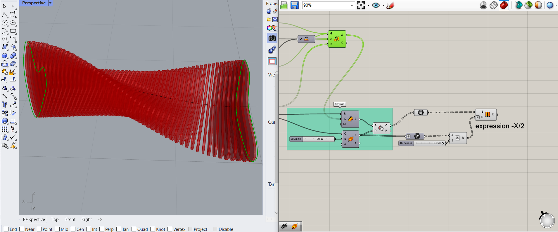
Now the curve needs to be divided through perp frames, with a number slider that can change the number of elements. Through a brep component shapes can be formed using the sweep and the division as inputs. Now the form of the bench is visible and is divided by 50 planes.

To actually generate the wooden components the brep needs to be transformed into planes. Each plane should be extruded into the z direction with a vector. At this point a problem occurred, because the planes are in groups, the vector not. Therefore, the vector needs to be grafted to also be in groups. To steer the thickness of the extrusion I added a multiplication component with a number panel for the thickness. To make sure the plane is at the center of the extrusion I added the expression -X/2 at the direction input of the extrusion.
A custom preview component and a color swatch steer the visuals of the bench.
3 l THE STRUCTURE
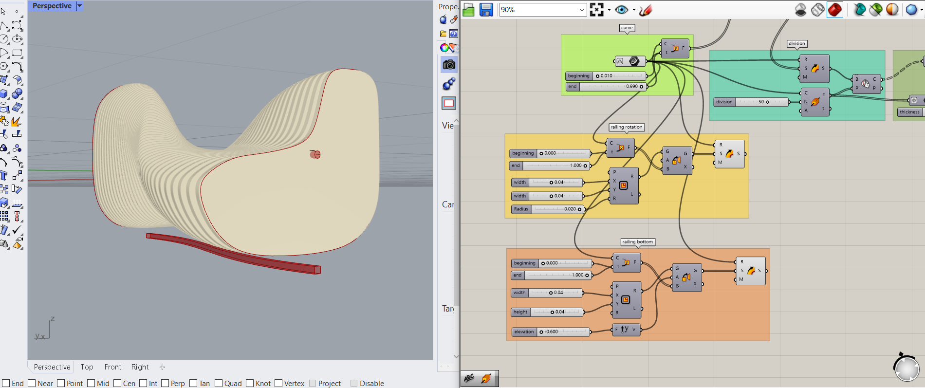
Now that the wooden components are completed the steel structure needs to be built. I created the middle railing with a rectangle component. This could have been a circle, but I wanted to be able to copy it after. Two number sliders control the dimensions of the rectangle and by adding a number slider to the radius the shape becomes a circle. I want the circle shape to be oriented on the original curve and its beginning and end planes through a perp frame connected to the curve. This time I set the number sliders to 0 and 1 to make sure that the steel structure is longer than the wooden panels. This circles should be oriented to those planes and a sweep component generates the round structure that the panels can be rotated around.
The next step was to create the bottom railing. For this I copied the top railing, with the difference of not rounding the rectangle through a radius. To move it to the bottom of the structure I added a y-vector and a number slider to change the height.
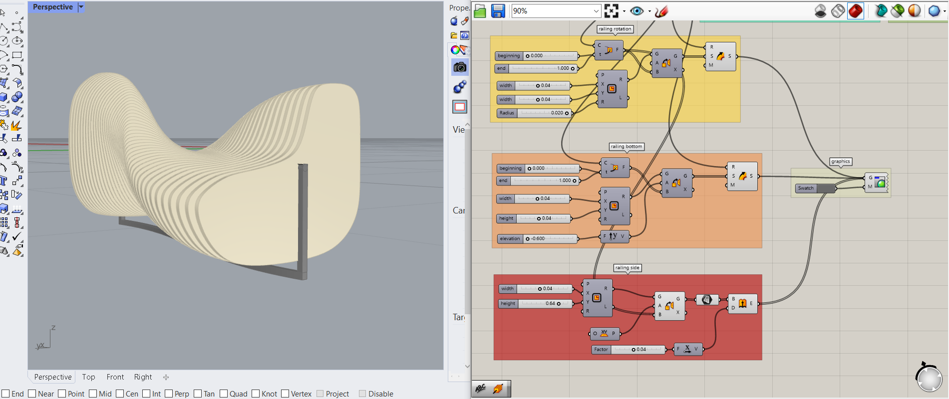
The side structure is also generated through a rectangle. This time I do not want a sweep. Therefore, the orientation component is connected to the perp frame that the railing is using. I added a plane instead of the sweep and extruded those planes through a number slider to create a thickness in the x direction with a unit-x component.
All three parts controlling the structure can also be visualized by adding a custom preview component and a color swatch.
By changing the number sliders for the rotation of the shapes the beginning and end shape can be turned into the sitting (1.5 x π) or lounging (1.0 x π) position. Any value in between rotates the elements a bit, therefore a sitting bench, a lying bench or anything between those two can be formed.

4 I THE ANIMATION
To animate the bench two options can be used. The first way is to animate the sliders. For that option the two sliders that rotate the shape of the bench can be animated after each other. The first rotation is animated through a right click on the slider and the option animation. After finding the right settings and exporting the images the second slider should be animated the other way around. For that the slider needs to be reversed through a substraction. Then this slider can also be animated.
To animate the emerged png files photoshop is an option to add them into a giph.
The second way to animate the bench is with the plugin “horster camera control for grasshopper” by fraguada.
https://www.food4rhino.com/en/app/horster-camera-control-grasshopper
After installing the plugin and adding it into grasshopper another curve which defines the camera rotation needs to be defined. The camera should be elevated from the bench so curve needs to be moved along the unit z through a number slider. To produce multiple images along that curve the curve needs to be divided (divide curve) into segments that can be controlled through a number slider. In order to move the camera along this curve the items need to be listed (list items). This list serves as a location for the camera which is added through horsters set camera tool. To give the camera a target a point needs to be difined in the middle of the bench to make the camera focus on the bench while rotating it. In order to steer the camera a boolean toggle can be added to the activate input of the camera. When turning it on (set to true) the camera movement is shown. To animate this rotation the number slider that counts the points along the curve needs to be animated. The exported images can again be transformed into a giph in photoshop.

The following video shows the two created animations.
5 I GRASSHOPPER FILE