ARCHED PAVILIONS
Autor Dariia Bodnaryuk
Intruduction
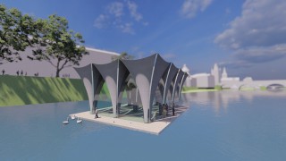
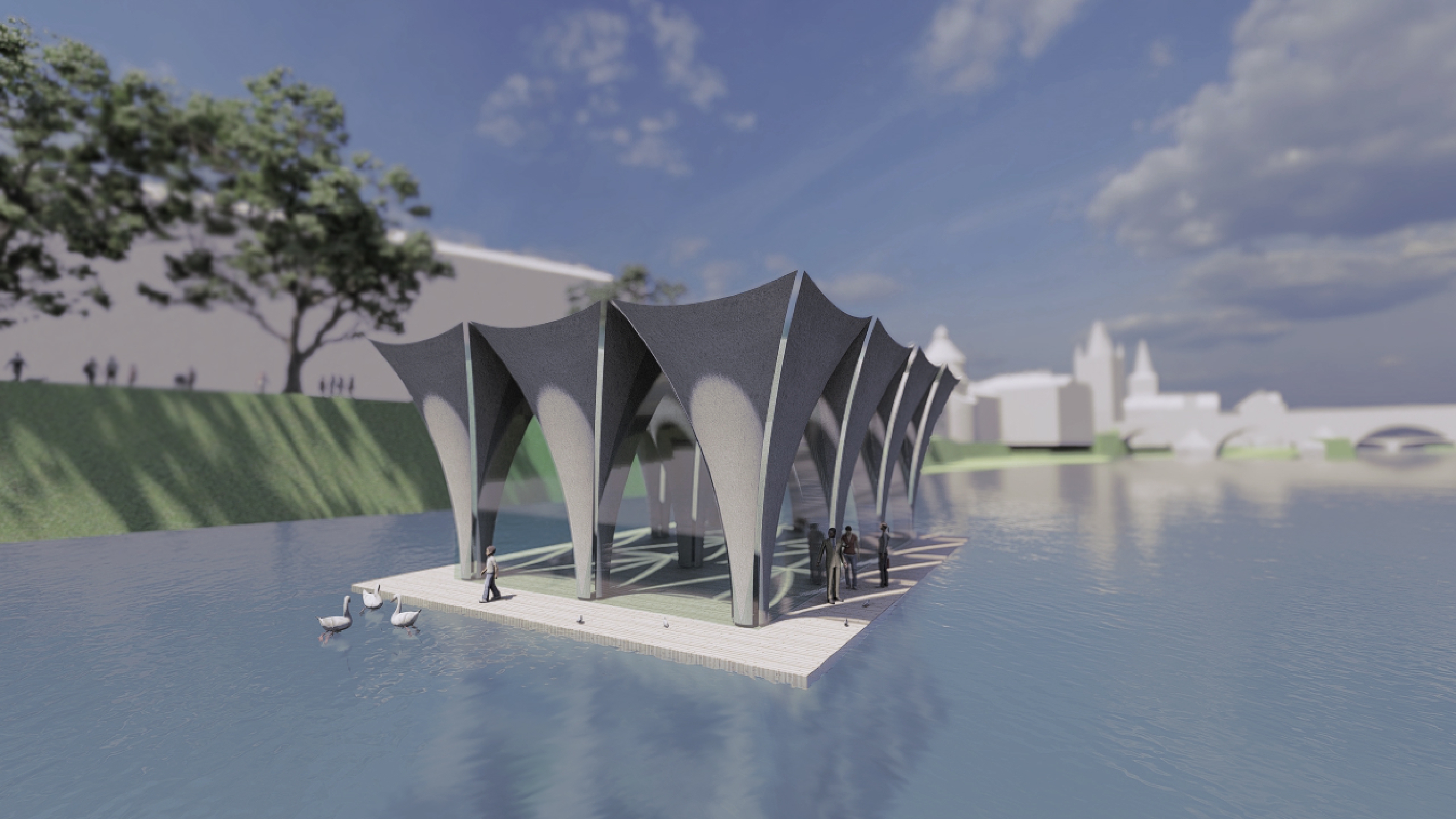
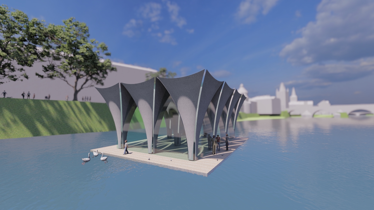
The pavilion will be located on the Vltava River near the city centre so I tried to make it fit in with the historic buildings and bridge architecture, and that’s where the idea of arches that will be glazed around the perimeter came from.
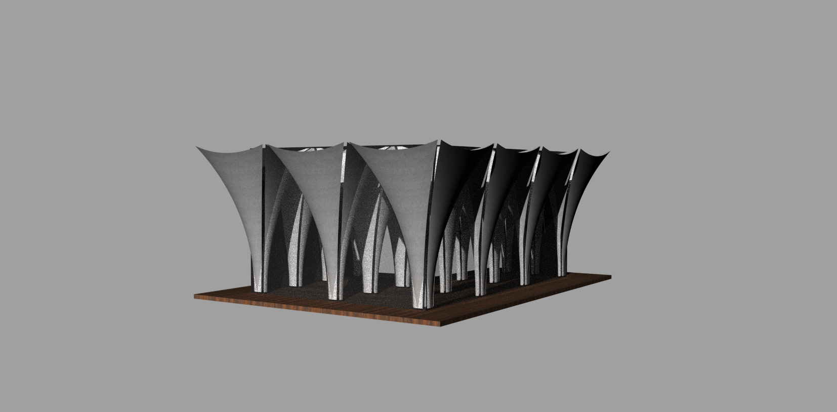
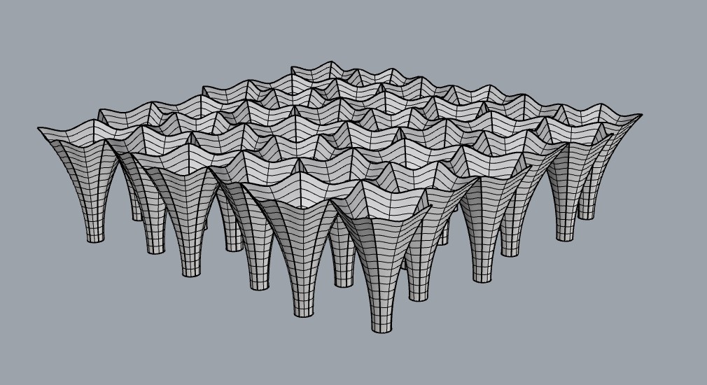
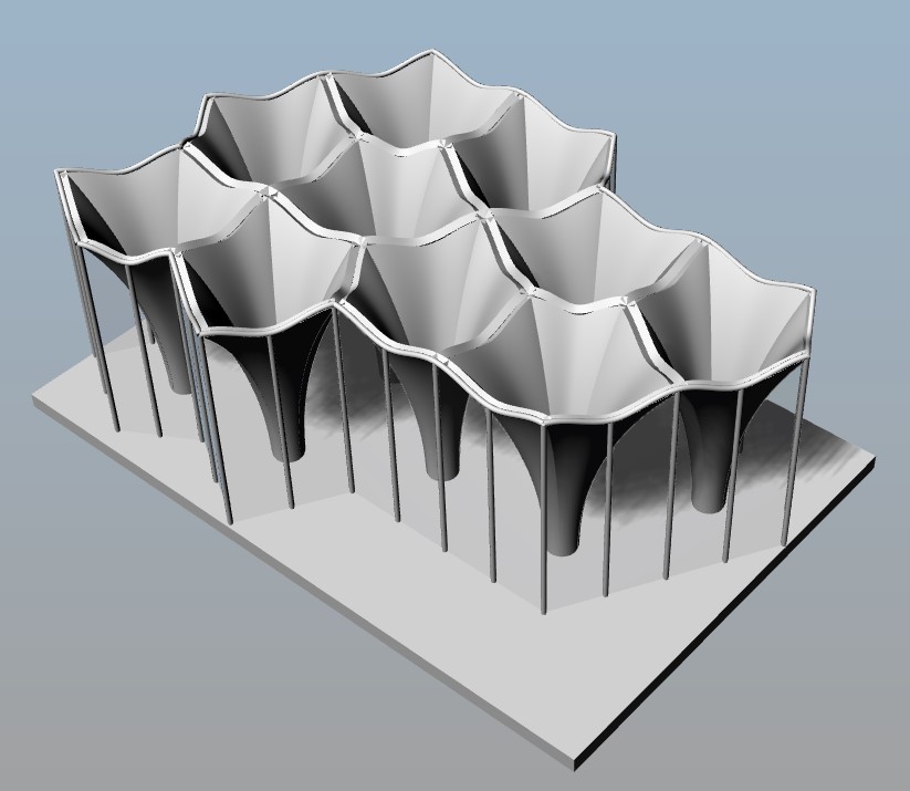
Structurally, the building is made of a modules that consists of 4 parts – “sails” each. The round column at the base transitions to a square ceiling plan. These modules are repeated several times. However, they are limited by certain dimensions in width and height. In order to be able to transport building under the bridges to safe it from floods. It’s actually more a ship then a building. According to the dimensions of the bridge spans, the maximum size is three spans of 4.5 metres each and 9 metres in height.
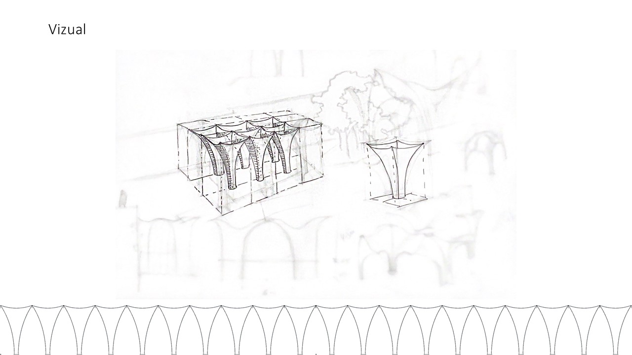
Vizual
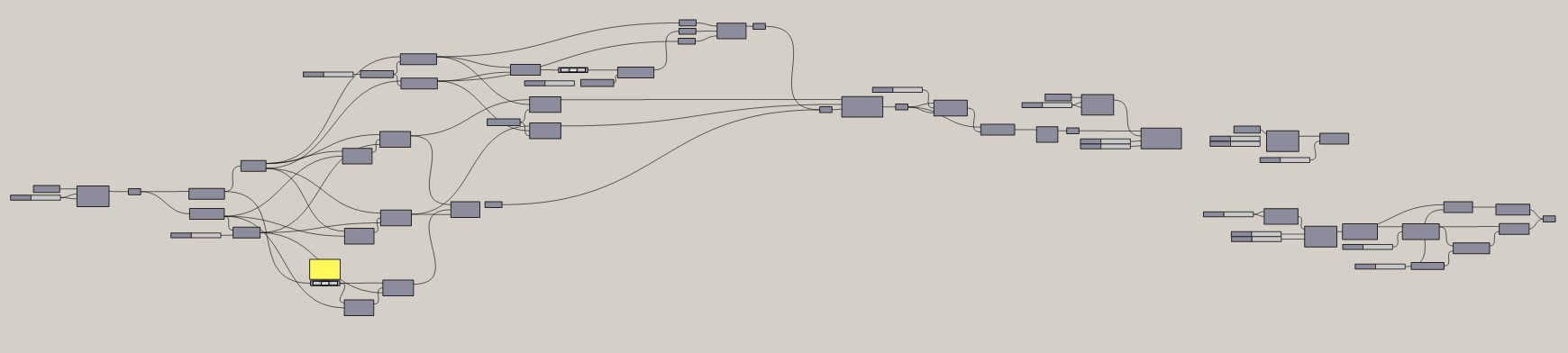
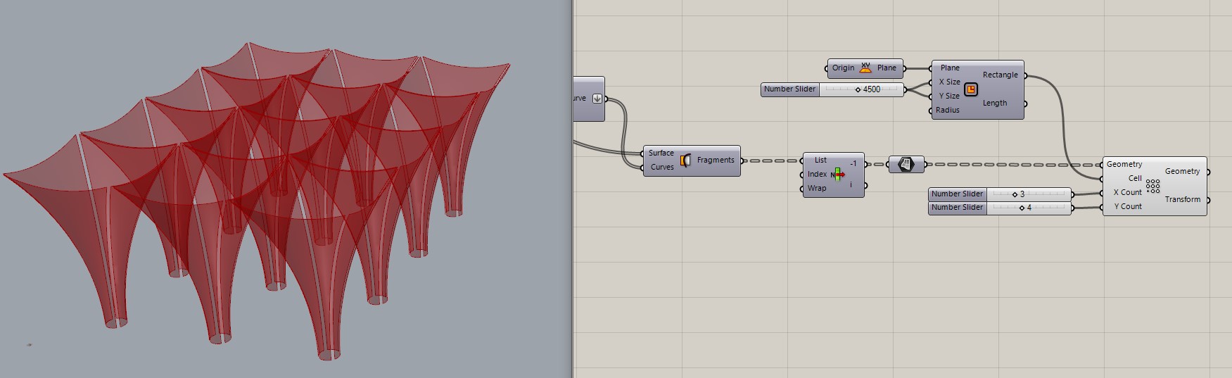
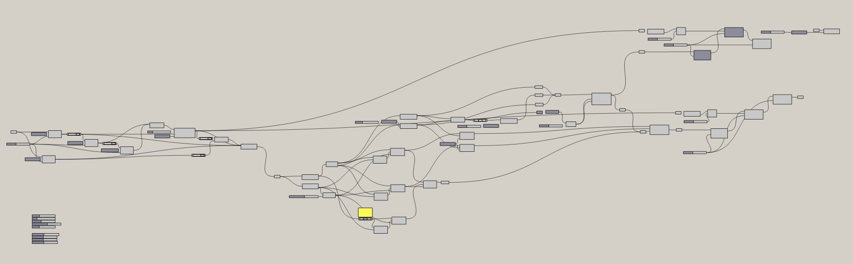
The whole script
Definition of the module, which will be multiplied at the end. Geometry projection assignment
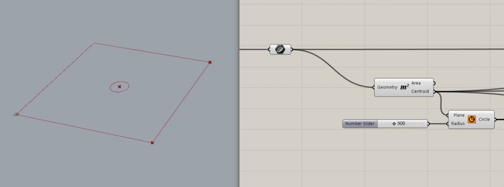
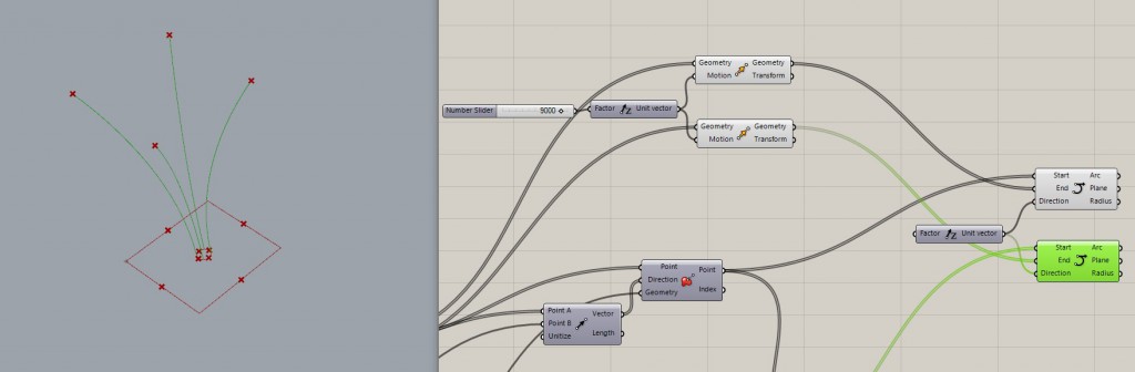
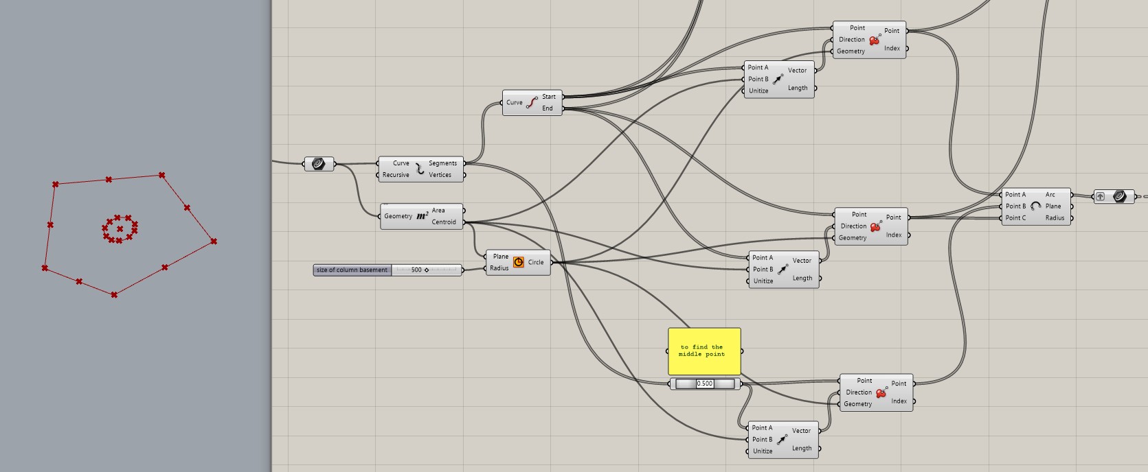
1. Creating a projection of the future column.
2. Creating the circle base of module. Exploding the curve to get segments and designate the start and the end dots – the projection dots of the future column.
3. Projecting points onto the base of a module. Start, End and Middle dots.
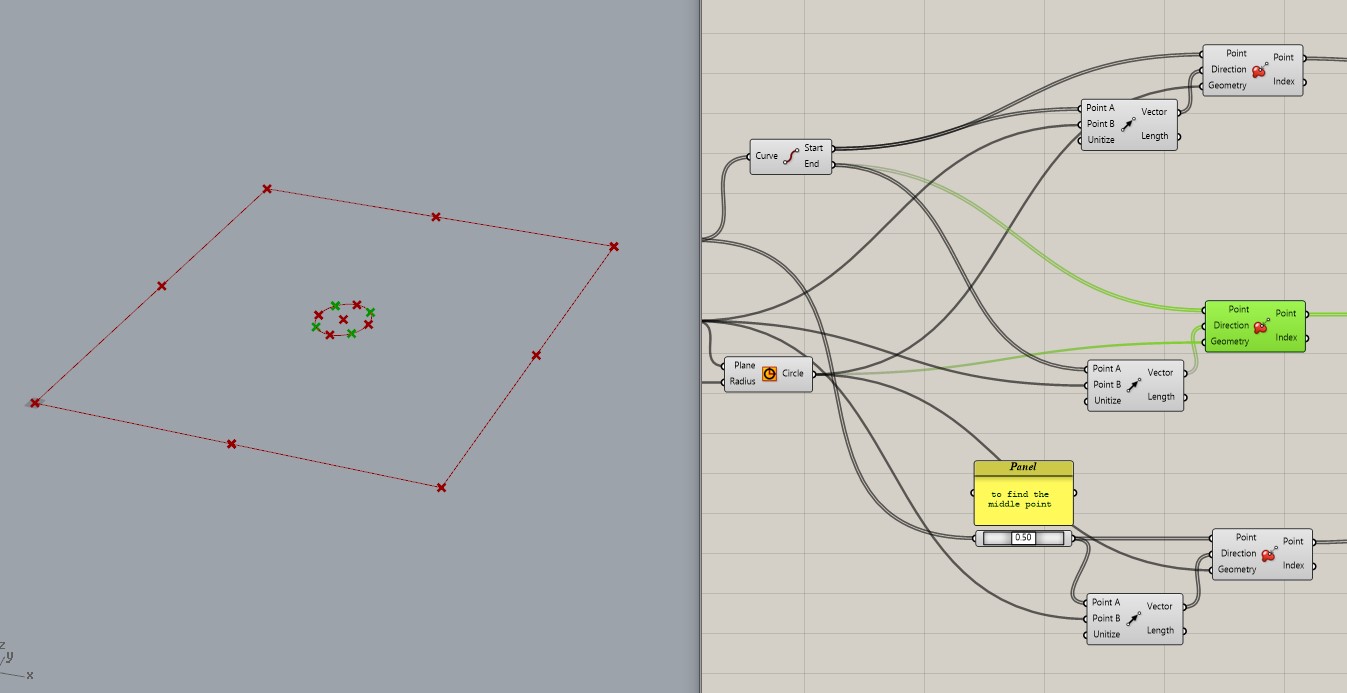
4. Dividing the centre into segments suitable for future arches each other. In order to create the correct surface geometry later.
5. Transferring the projection points upwards -they will be the arch support points.
Constructing geometry
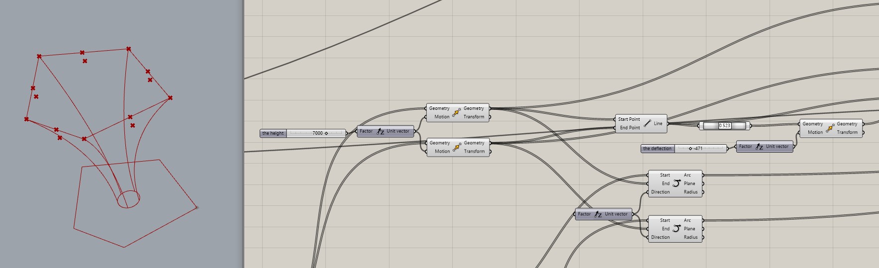
6. The side edges of the module, connect the projection points on the base and the support points of the arches. The command is duplicated because one edge cannot belong to two sails. Connect start points to start points, end points to end points.
7. Finding the deflection point. Did the connection between support points, find the middle dot and project it on the height of deflection.
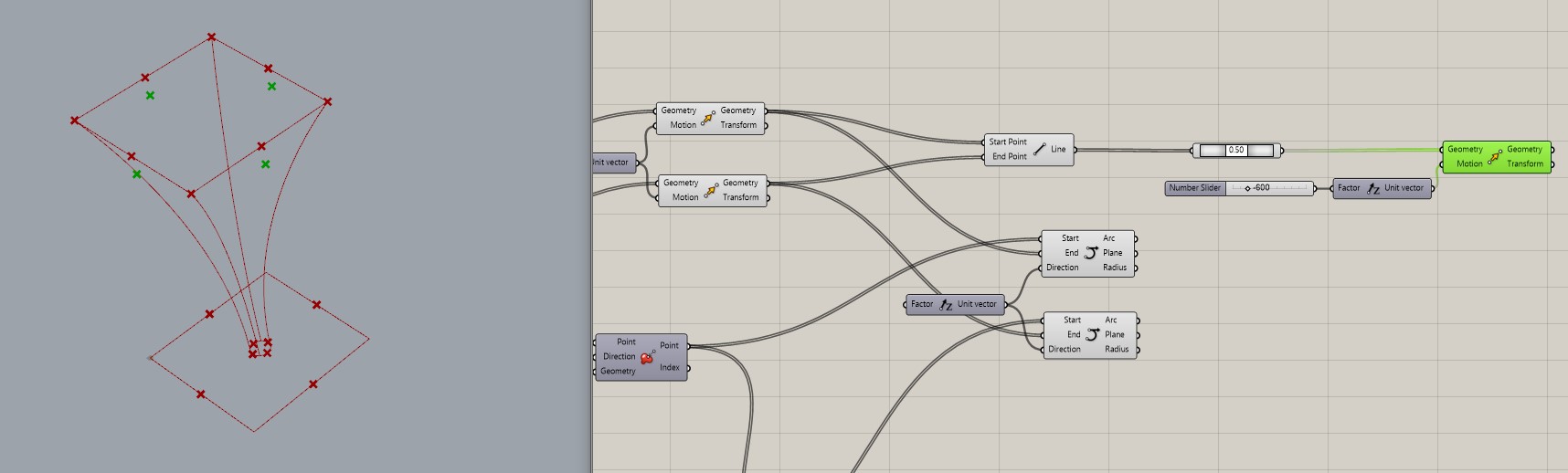
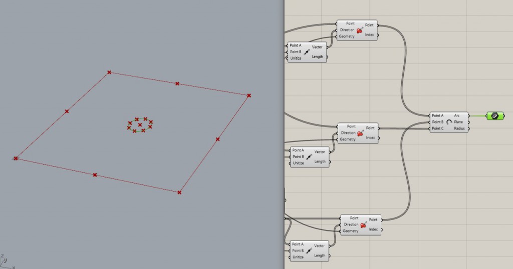
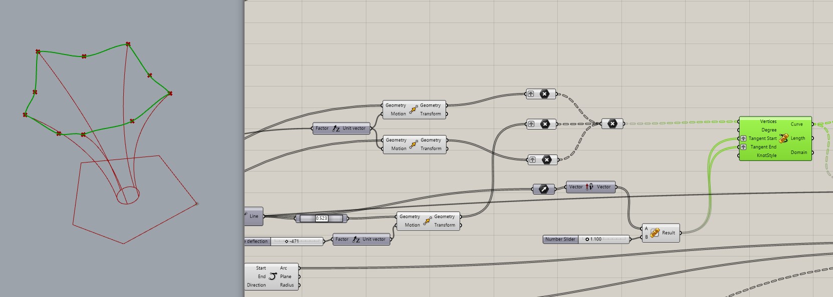
8. Creating an arch on 3 points. Need to do them Graft to get groups of three dots to be able to create a surface.

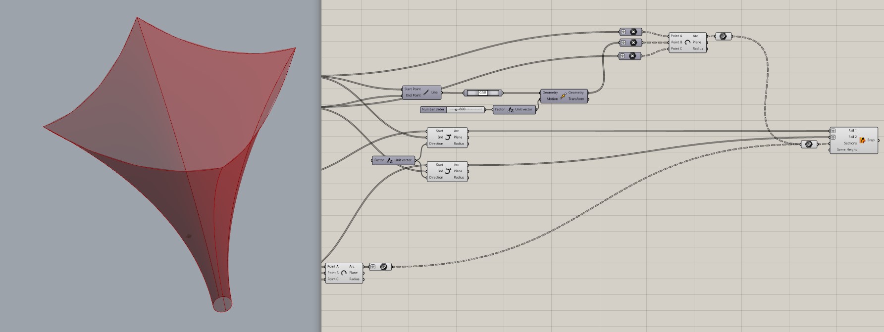
9. Creation a skin by rails – edges.
Details and multiply
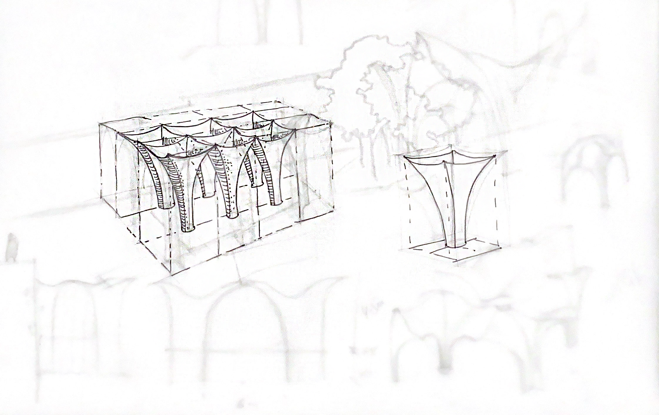
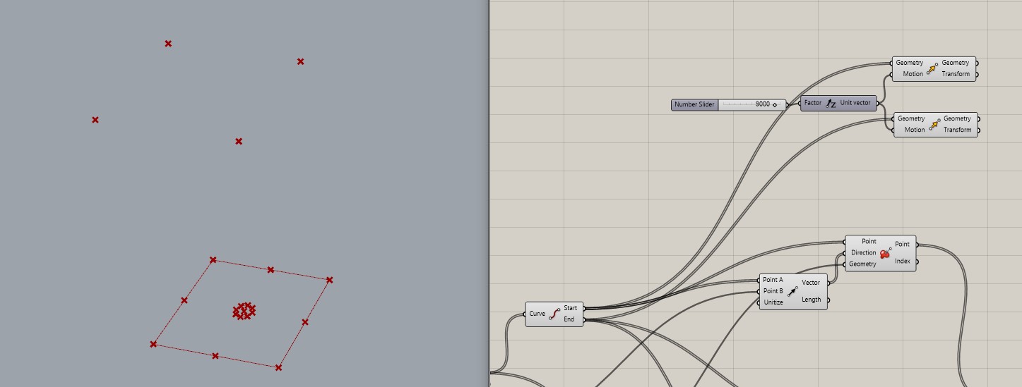
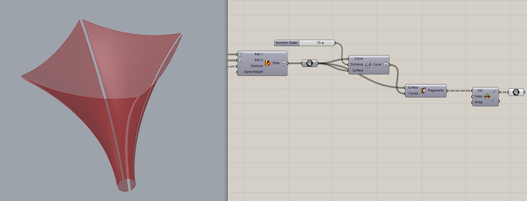
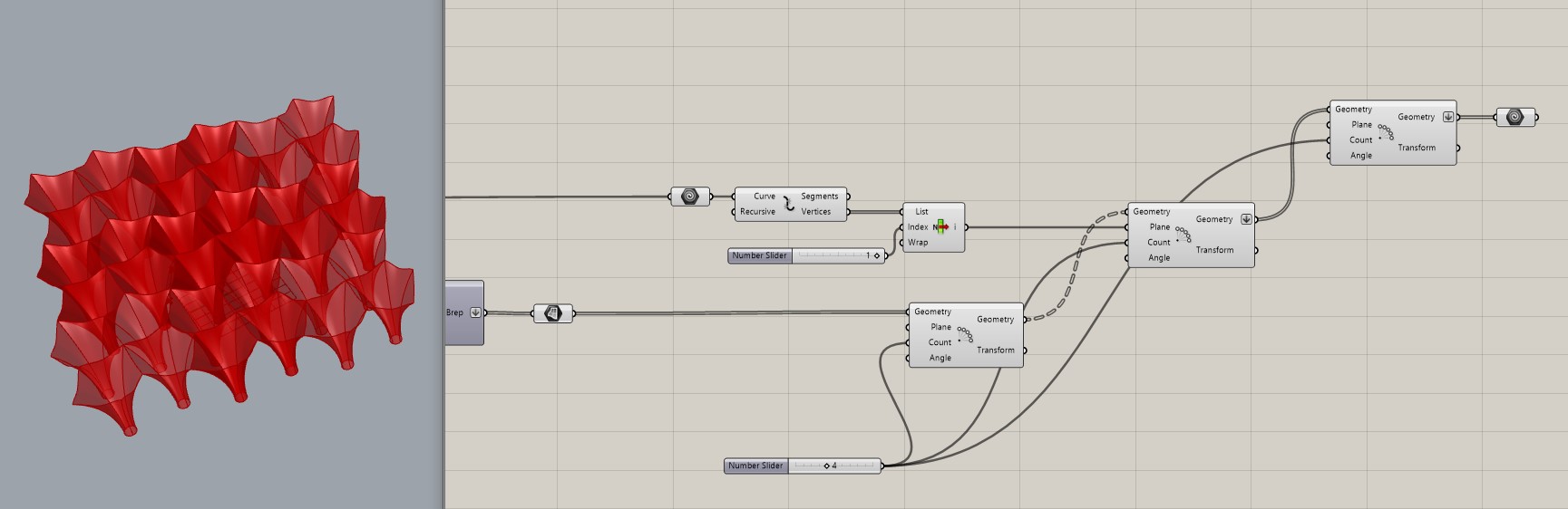
10. Dividing sails into four different parts.
11. Multiplying with the ability to set the number of modules per axis.
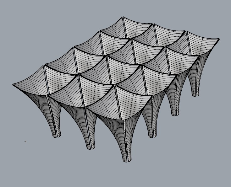
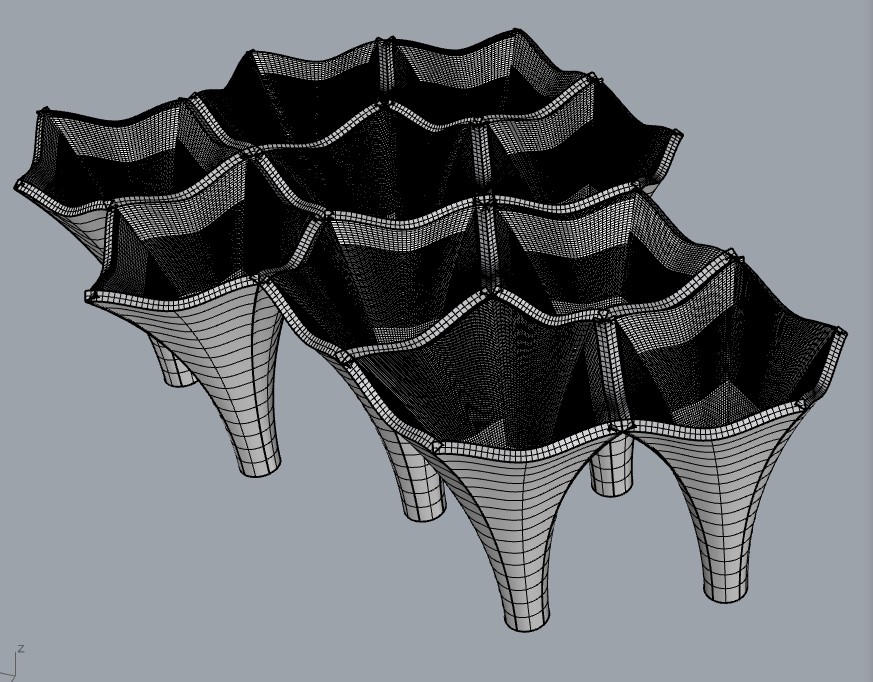
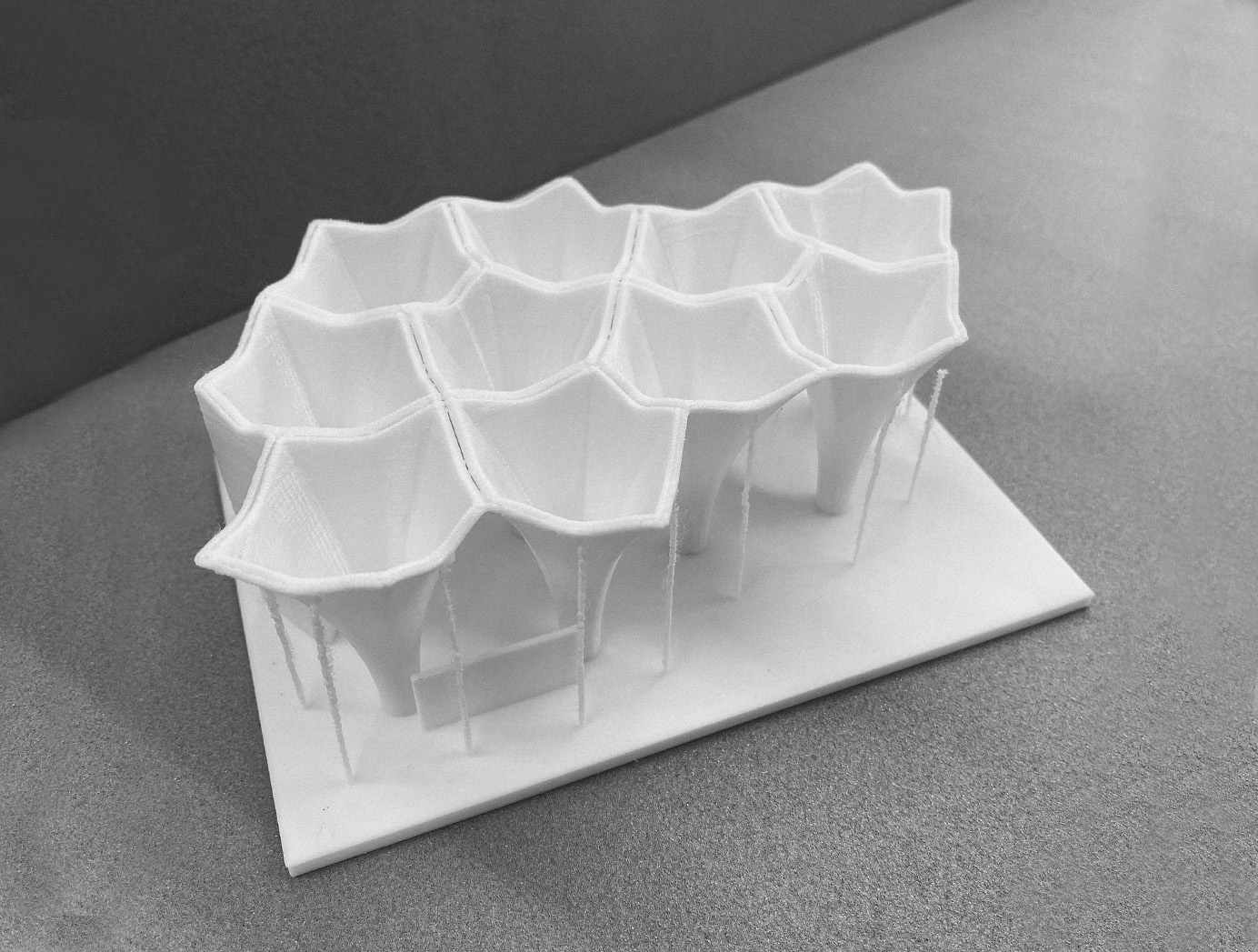
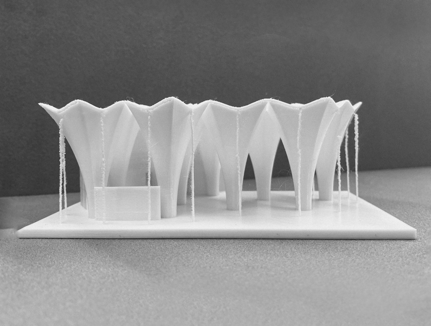
12. This is how finished basic geometry look like.
Foundation and glazing
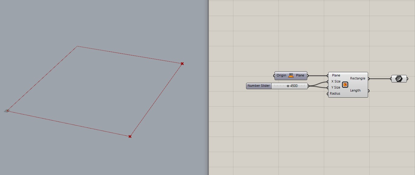
13. Creating a simple box for foundation.
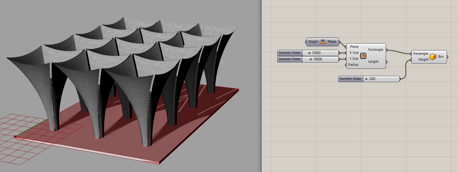
14. Glazing with fixed size of windows-walls.
Final results
1. GH file: arch_pavillion1
Modified version
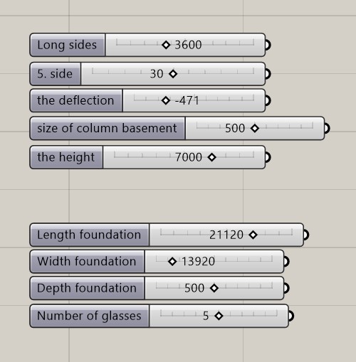
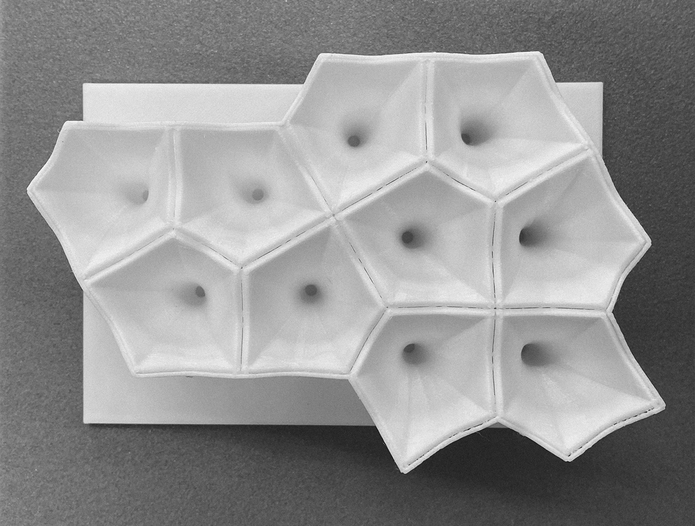
The main differences of the new model: new adjustable pentagonal plan for the module, smooth deflection point, different type of module multiplication – polar.
Basic design of the module
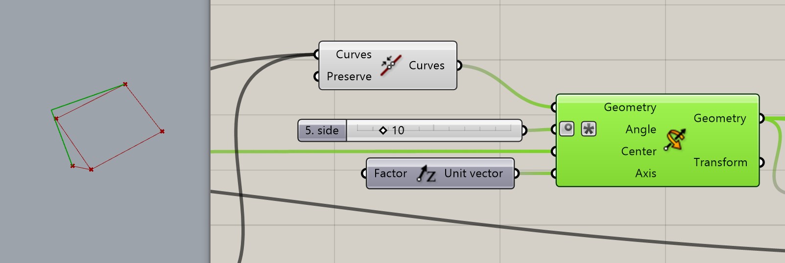
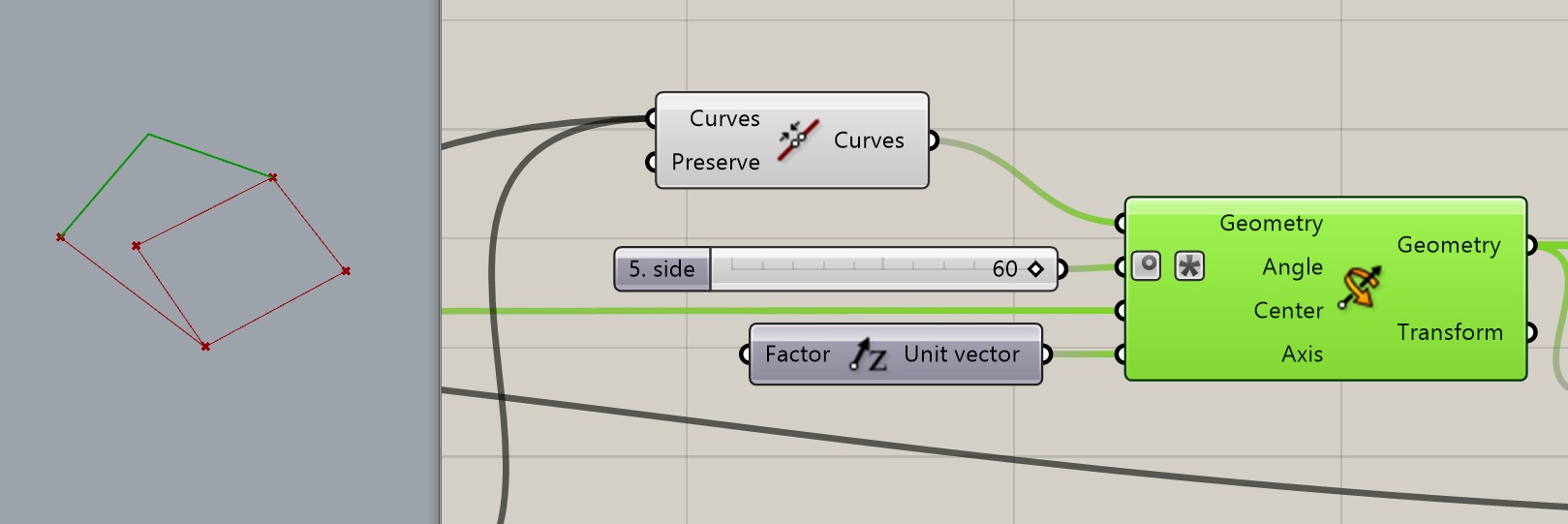
2.1. Creation the lines on plane to find the end points and to create the 5th side.
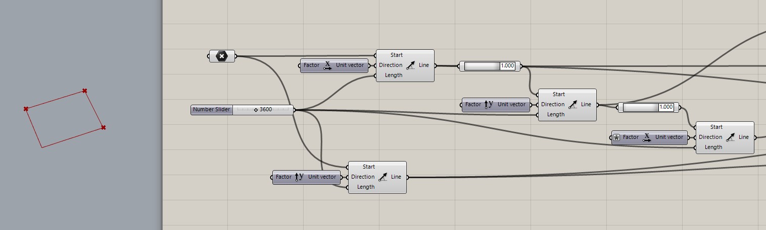
2.2. The next step to create the module´s plane.

2.3. The variations of plane.
2.4. The similar actions in paragraphs 2 – 4.
Creating the circle base of module. Exploding the curve to get segments and designate the start and the end dots – the projection dots of the future column. Projecting points onto the base of a module. Start, End and Middle dots. Dividing the centre into segments suitable for future arches each other. In order to create the correct surface geometry later.
2.5. The similar actions in paragraphs 5 – 7.
Transferring the projection points upwards -they will be the arch support points. The side edges of the module, connect the projection points on the base and the support points of the arches. The command is duplicated because one edge cannot belong to two sails. Connect start points to start points, end points to end points. Finding the deflection point. Did the connection between support points, find the middle dot and project it on the height of deflection.
2.6. Creating the top arch.
Surfaces
2.7. Creation a skin by rails – edges. At this paragrapt, it is important to connect the different edges in the correct order to the creation of the general geometry. First the base, then the upper perimeter. Then send it to the “sweep” – creation of the surface.

Multiplying
2.8. Polar multiply sets of basic plane geometry from the paragraph 2.3. and the ready module from the 2.7. paragraph. It repeats several times to have the possibility to choose the needed final geometry in the future post processing.
2.9. The basic geometry is ready changes in Rhino.
2.10. In Rhino delete the unneeded modules and set the width of construktion with “offset” command.
The controllers
Glazing
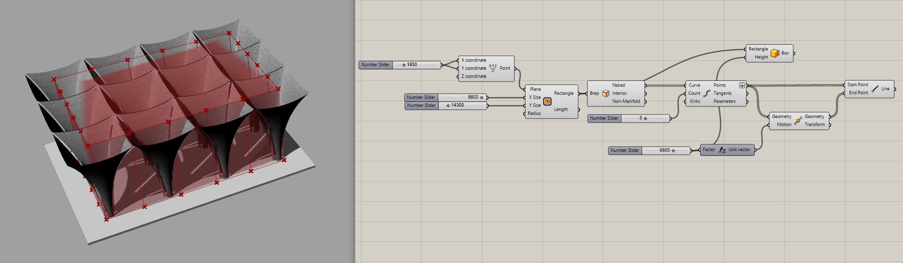
2.11. Multiply the upper perimeters and bake it. Delete the unneeded ones. Set on the remaining lines to extrudition to take the glazing.
Repeat the 13. paragraph to create the foundation.

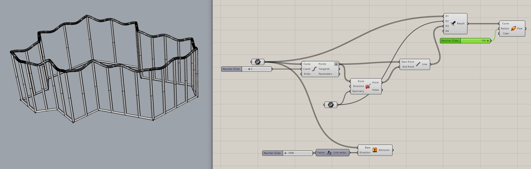
2.12. To take the frame of glasses take the received lines and project them to the foundation. Then connect points and offset with pipe.
Final results
The 3D printed model
1. GH file:arch_pavillion1
2. GH file:arch_pavillion_new