
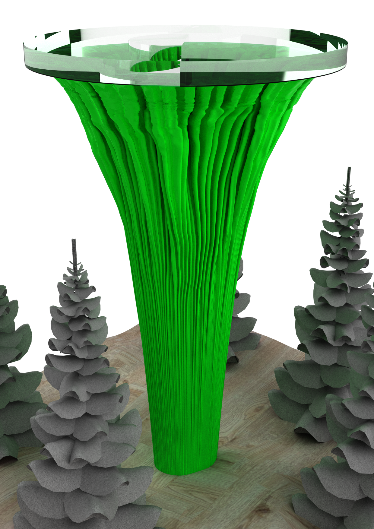
COVER
CONTENT
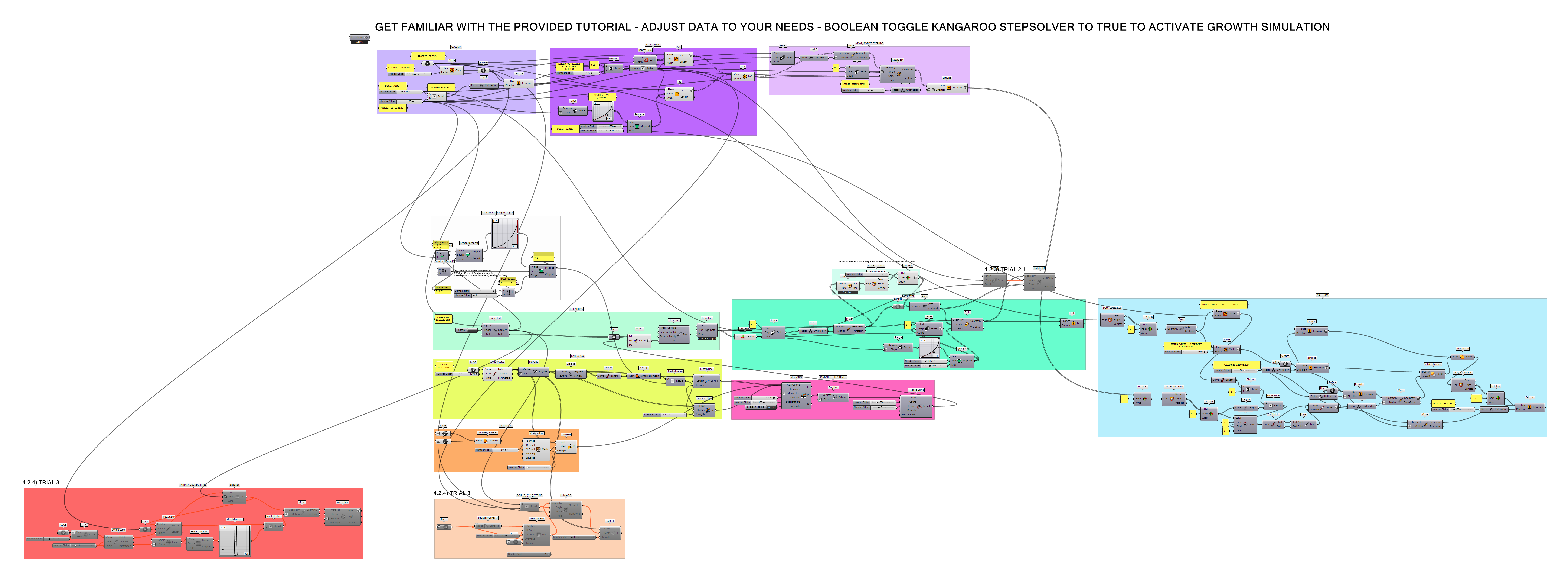
This tutorial demonstrates the Growth Simulation principles inspired by https://www.youtube.com/watch?v=viEpaivq9A0 . It provides users with a parametrical column with stairs along with a Kangaroo and Anemone script of biomimic principles of kale. The script also contains an example of creating a parametric platform for lookout towers.
INTRODUCTION
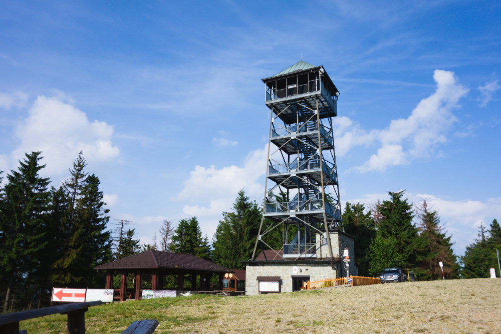
Kale lookout tower is a continuation of my lookout towers projects inspired by nature as a reaction to rigid steel structures found in forests having nothing in common with nature surrounding the object, like a lookout tower in Velká Čantoryje mountain.
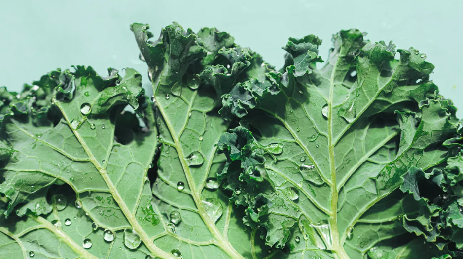
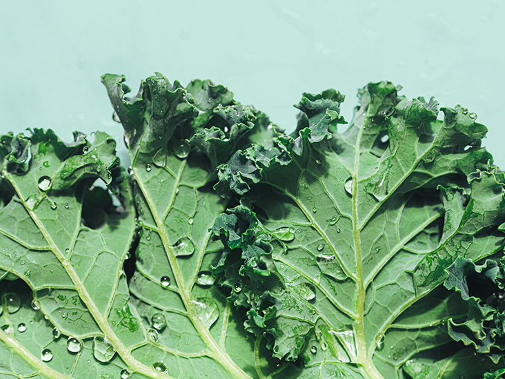
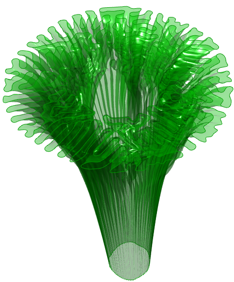
 In my tutorial design I approach the lookout tower to be designed by nature and I develop a Kale inspired lookout tower on biomimicry level. Kale’s leafs even when straighten don’t form a flat surface as they expand their leaf area as they grow and achieve a higher coverage. Doing so they also form an appealing biophillic design suitable for the architecture situated in the nature.
DESIGN STEPS
- Create a spiral staircase with a height of 30m (custom – to compare the final design with Velká Čantoryje lookout tower). Script width parameter into stairs through Graph Mapper to match the increasing radius of the kale growth.
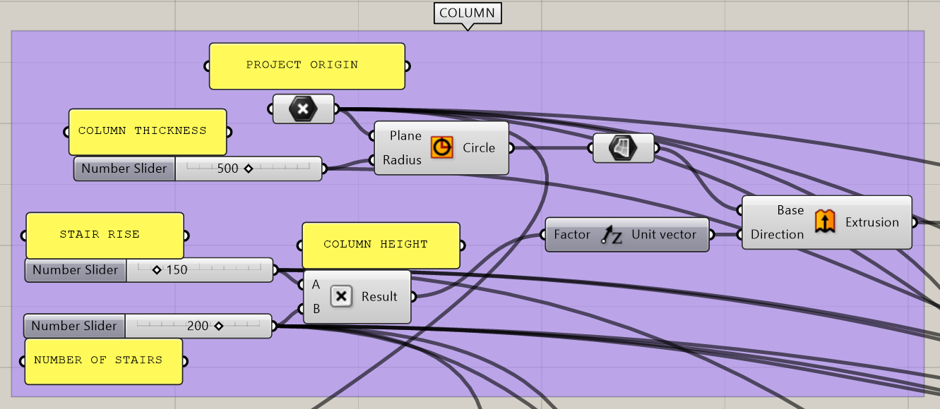
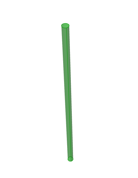
1.1) Creating a COLUMN
Workflow I used in this tutorial is setting a Point in Grasshopper for the circle to be able to move the design parametrically as a whole from PROJECT ORIGIN. I set a description of the Sliders using Panel to have a clear understanding of my variables control (even though you could change the name of the Slider directly in its build-in options, I prefer to use Panel to have the visual eye-catcher). It is also a desired practice as a new user of the script will quickly understand the built algorithm.
The desired column height of the 30m (30000mm) has been dictated by the STAIR RISE and NUMBER OF STAIRS Sliders in order to finish exactly at the location of the last created stair.
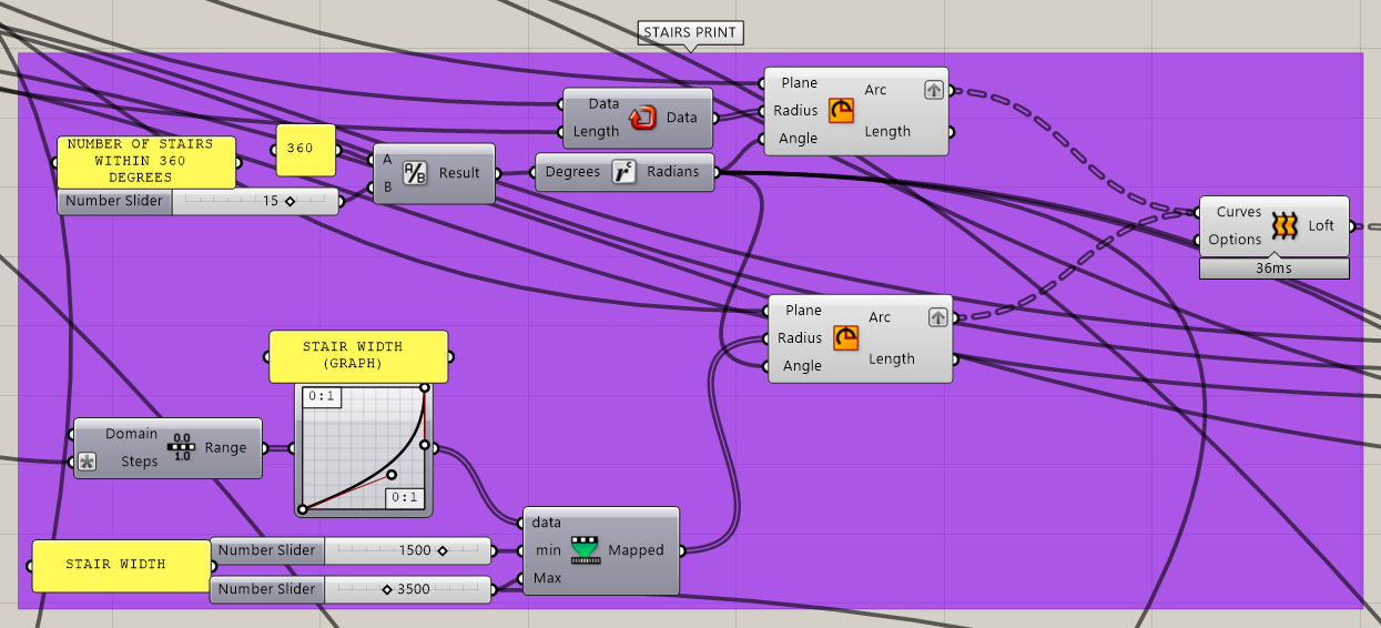
1.2) Creating a STAIR ‘PRINT’
NUMBER OF STAIRS WITHIN 360 DEGREES is controlling an angle based on which an actual stair will be created. Graph Mapper with Remap + (custom component using Remaps and Bounds) controls custom STAIR WIDTH. In order to loft the two created arches we need to Graft them both. Initial Arc had to be fed Repeated Data of COLUMN THICKNESS and NUMBER OF STAIRS in order to create an adequate number of elements.
For values (variables) that are interchangeable as e.g. I will always want 360 degrees to be divided into number of stairs within one full circular rotation I will use Panel to encode the number in order not to have a visual Slider overload and confusion of which values are adjustable and which should not be altered and are fixed.
We also need to make sure to set an expression to range “x-1” in order to have exact number of elements we feed the component with our Slider.
1.3) MOVE, ROTATE, EXTRUDE the created stairs
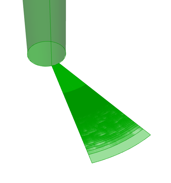
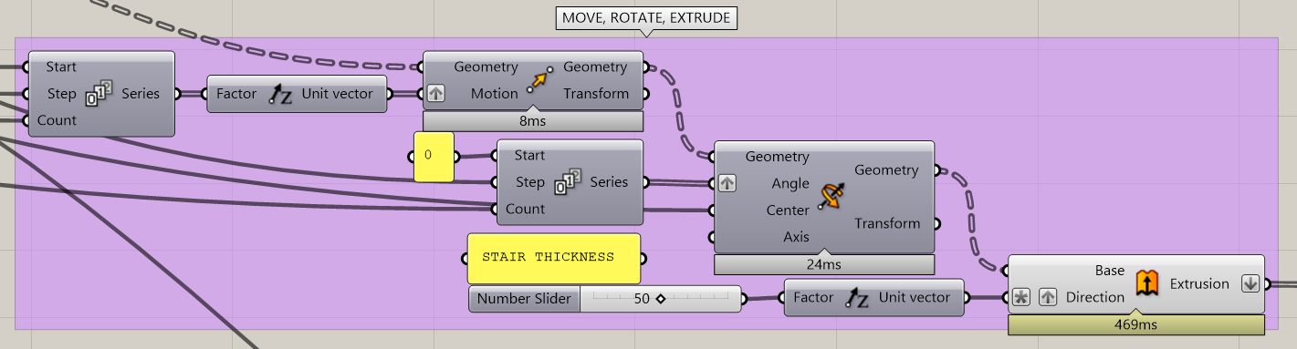
We Move created STAIR ´PRINT´ in the ´z´direction using the Series for the Factor of Unit Z with the Start and Step of the STAIR RISE and Count of the NUMBER OF STAIRS to match created and moved Geometry. Moved Geometry has to be then rotated using similar Series principles, but with the step of created angle. A simple extrusion follows with Negative expression of ´-x´ to create the STAIR THICKNESS downwards in ´-z´ direction making sure that the STAIR RISE is accurate even for the first created stair and not being a number of addition of STAIR RISE + STAIR THICKNESS.
- Creating a cover base algorithm using growth simulation.
2.1.) Creating the base and Kangaroo Solver
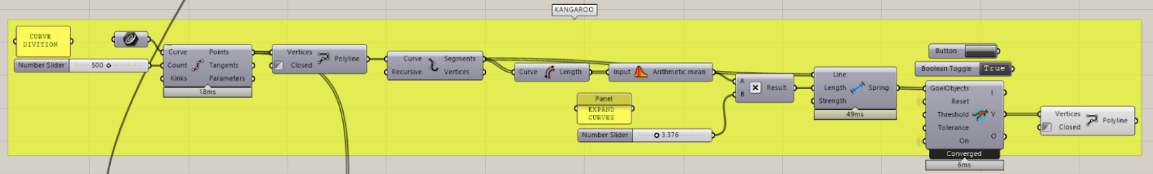
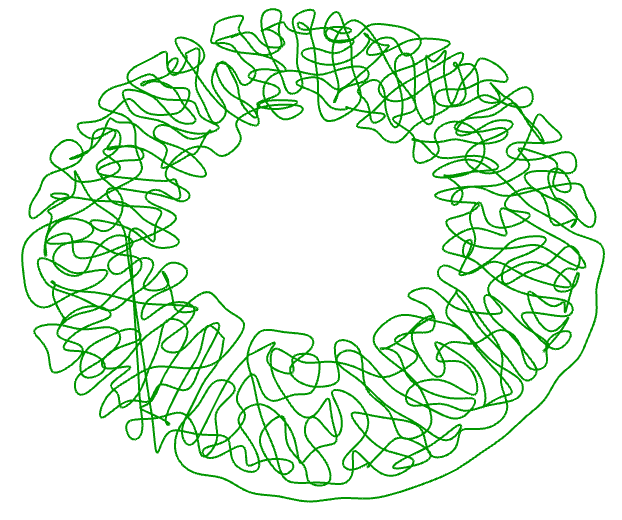
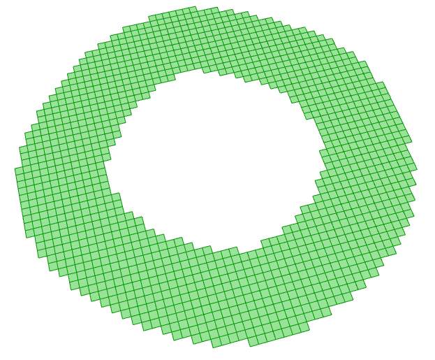
We create a base in Rhino (organic curve using Control Point Curve tool) according to project scale and set it into a Curve in Grasshopper with the idea of future possibility of adjustments. We need to rebuild the Curve in Grasshopper for it to have segments by using Divide Curve and later Interpolate with Inverted value for its Closed Input to have a closed curve.
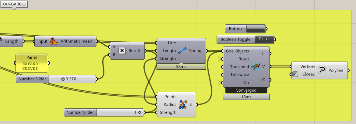
We Explode the Polyline with the idea of expanding the created line segments with Kangaroo Solver. We first find the polyline segments length using Length command and later taking their Average and Multiplying the result to expand out desired output.
From our Solver output we are interested in V (Vertices) which we can rebuild into a Polyline again.
The algorithm as it is now doesn’t give desired results as the lines intersect and we need to feed our Kangaroo Solver with additional components.
 2.3.) Kangaroo Solver
We need collision detection for the segments not to intersect so around each point we need to create a sphere and doing so the Kangaroo Solver will not let the spheres intersect each other therefore the lines should not intersect each other either.
We use Kangaroo SphereCollide and for its Radius input we can reuse our Average Length Multiplication.
We can also match the Strength input of Kangaroo Length(Line) and SphereCollide for better looking results.
2.4.) Boundary condition
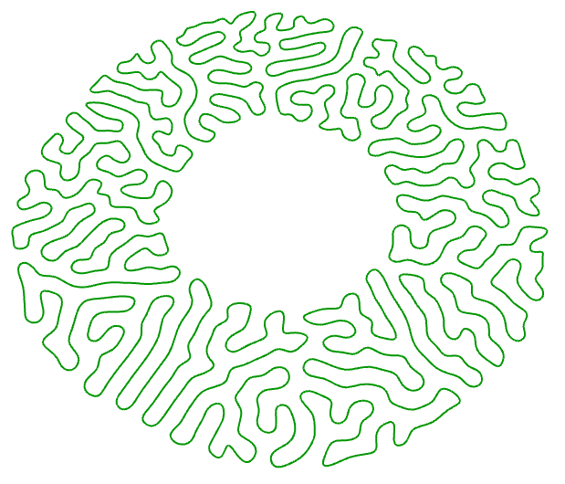
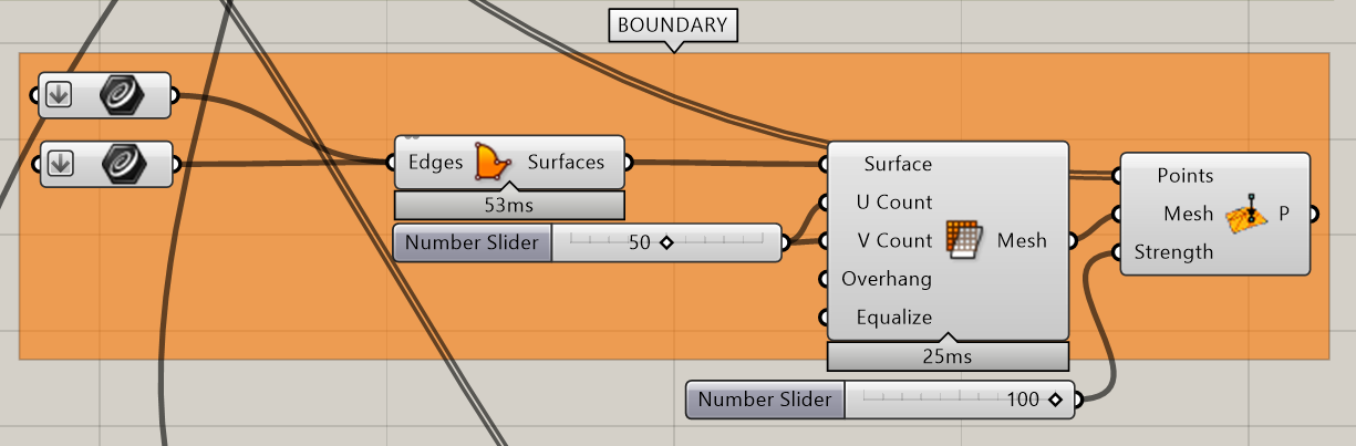
We set a boundary for the curve expansion so we control its area and design growth simulation reach. For our points to stay in the area we will use the command OnMesh.
We proceed by scaling and copying a previously created curve inwards and outwards in Rhino and creating a surface using Boundary Surface out of the two curves. As command OnMesh needs a mesh for one of its inputs to work from, we need to transform our created surface into a mesh using Mesh Surface command.
In case the points still expand beyond the mesh do increase the Strength input of OnMesh command.
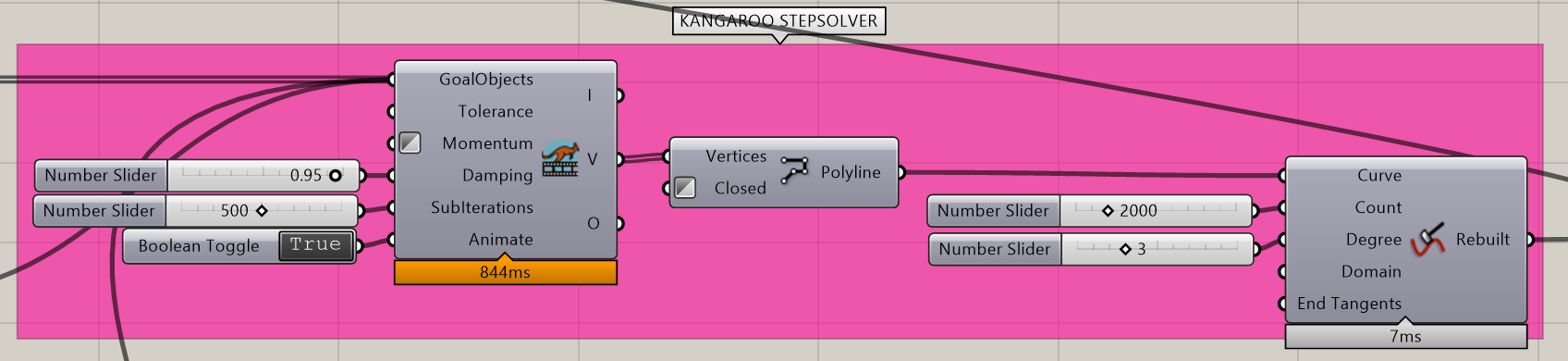
2.5.) Kangaroo StepSolver
After knowing our initial algorithm works in Kangaroo Solver for the next steps we need to change it to Kangaroo StepSolver as a regular Kangaroo Solver is constantly running and we would prefer our design to work in steps.
We Invert its Momentum input so it runs slower with higher precision.
For input Dumping we set a value in which percentage of speed the points will move between the iterations.
We can also add a Rebuild Curve component to rebuild the created polyline into a polyline with more control points making it even smoother.
Be wary of the need to switch the Boolean Toggle from True to False to True and then Trigerring the Anemone loop Button after making certain design changes or changes in variables that affect the iterated curves in any way to see the correct results.
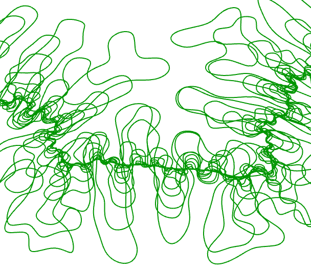
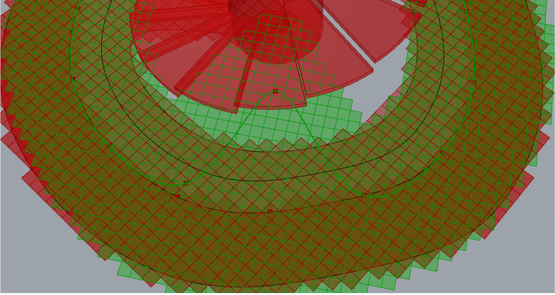
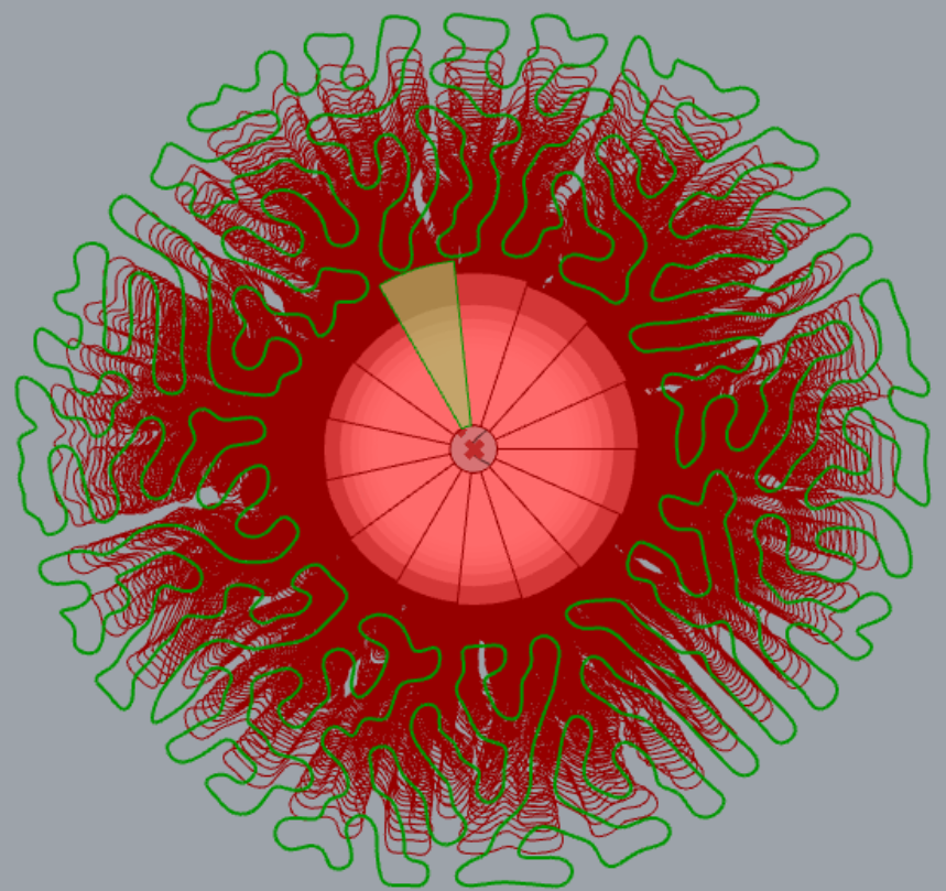
- Tactically use a created base of scripted growth simulation to biomimic the kale leaf structure. It is desired that we create a continuum of growth sections from the bottom to the top of the lookout tower. To do that we will use the created and implemented Kangaroo Length(Line) component as it is stretching the curve segments based on its Length input. As a working method we will be using Anemone plug-in with loops as we want the stretching to be done through iterations.
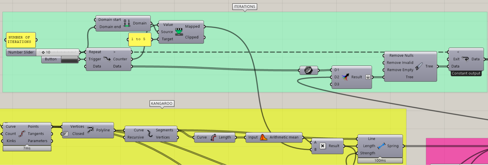
3.1) Creating ITERATIONS
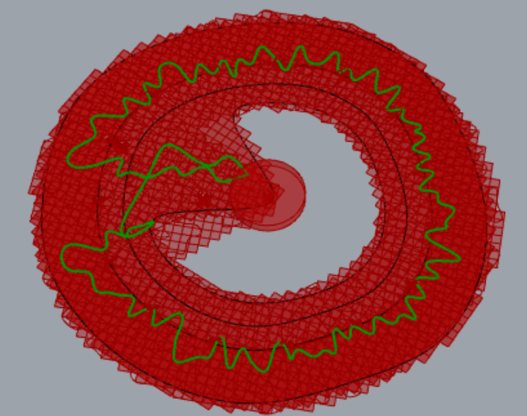
We set the desired NUMBER OF ITERATIONS and a domain to Remap it to as we want to have a control over the Length input of the Kangaroo Length(Line) component. The Data produced from the Loop Start are Periodic Planar Curves that we need to Merge with the final created, but not included curve through from the iterations.
We Flatten the merged curves and Clean Tree the data to safely continue with proper information content.
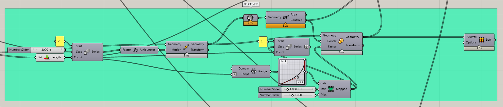
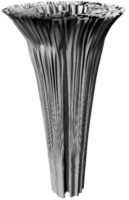
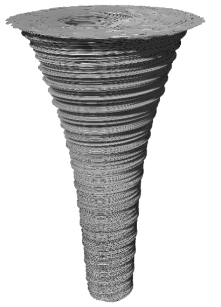
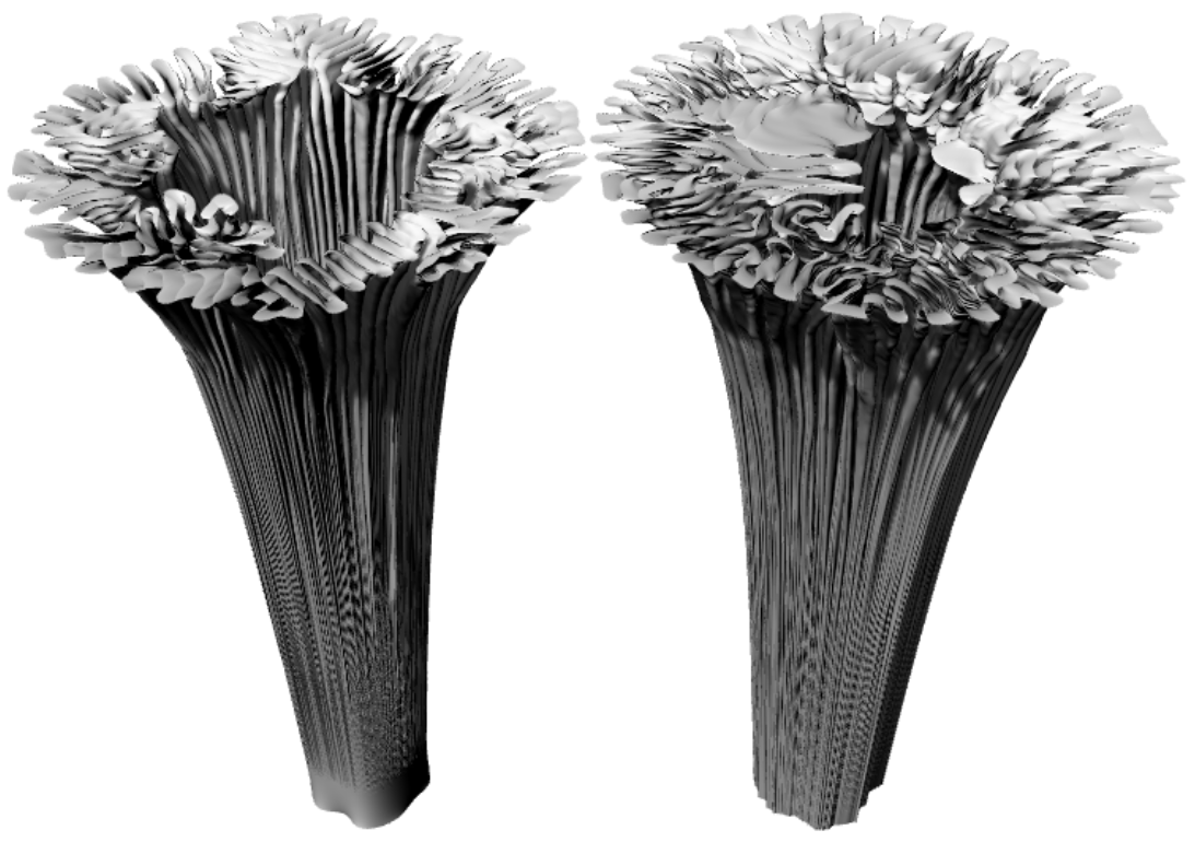
3.2) Creating 3D COVER
We simply create Series of the iterated curves and move them in the ´z´ direction, where we proceed by scaling them knowing their Centroid using Graph Mapper to alter the variables and Loft in the end to complete the 2D to 3D process.
- Consultation with Ing. Arch. Šimon Prokop and early script and design alterations. To complete the project only platform and possibly an entry would be required, but with Šimon we agreed that it would be better for the project if the staircase and 3D cover are not separate components, but they interact, merge and co-function.
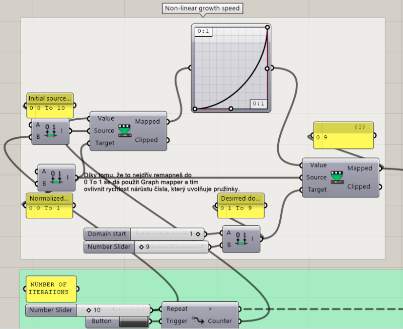
4.1) Implementing Non-linear growth speed
For Šimon it was also more interesting that the remapped iterations controlling lookout tower growth simulation would not be linear, but non-linear using remapping technique to 0…1 domain initially and graph mapping it after using non-linear Graph type.
4.2) Merging 3D cover with the stairs
A possible way to do this would be by controlling and altering the BOUNDARY and the created initial Rhino curve along with creating sections of the 3D COVER dictated by STAIR RISE.
We start by disabling the parts of the script that we will not need now as the 3D COVER group as we do not want it to stress the software processing capabilities and we only want to focus on experimentation of part of the algorithm.
4.2.1) TRAIL 1 – altering the created Surface Boundary by recreating the inner curve so that it allows for the lengthened segments to fill the space under the stair

Immediate problem has been noted and that is that only the final interaction expands enough to infill the recreated boundary space fully.
4.2.2) TRIAL 2 – altering the created initial Rhino curve to have the origin of the segments lengthening already in the shape of the boundary
In this case the lengthened segments continued to successfully infill the altered boundary space. The only concern has risen for the deformed structure and its non-continuous exterior appearance.
It had to be further tested by enabling the 3D COVER group and Baking the final Loft and assessing it in a Render Perspective View in Rhino viewports.
I have decided that it would be an interesting aspect of the design and processed to keep it.
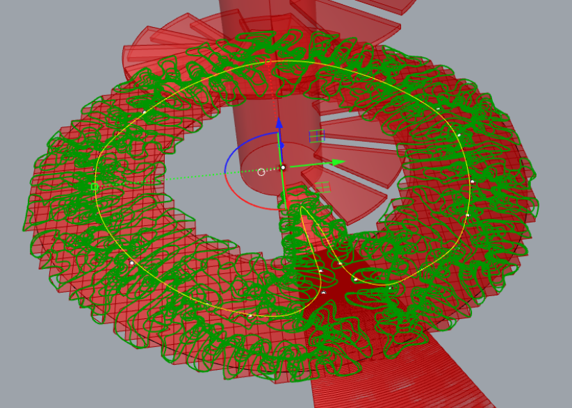
4.2.3) TRIAL 2.1 – creating sections for each stair as in TRIAL 2 and rotating the boundary accordingly using Rotate 3D on iterated curves after scaling in 3D COVER group
For NUMBER OF ITERATIONS I used NUMBER OF STAIRS and moved the sections in ´z´ direction with the value of STAIR RISE. Before lofting I used the command Rotate 3D in order to rotate each iterated curve by the set angle in STAIR PRINT group.
The resulting outcome was not a desired geometry due to the close distance of the segments to the rotation ratio and the process had to be reevaluated.
4.2.4) TRIAL 3 – altering the initial Rhino curve to curve into the footprint of the stairs accordingly with every iteration along with rotating the boundary accordingly with every iteration
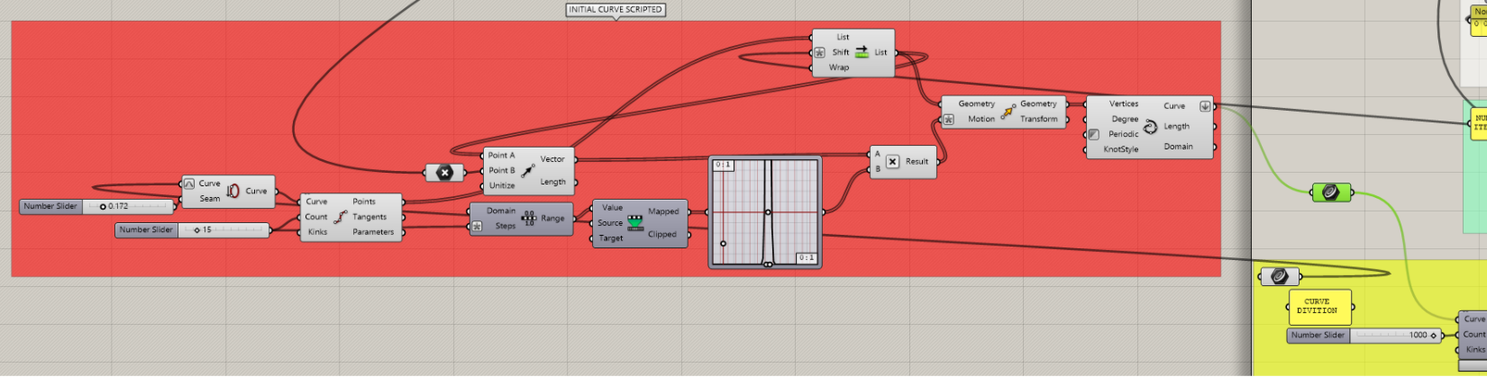
The idea is to divide the initial Rhino curve to generate points which can be interpolated back to the initial curve with the twist of manipulating the points using Graph Mapper and Vector 2Pt directed inwards.
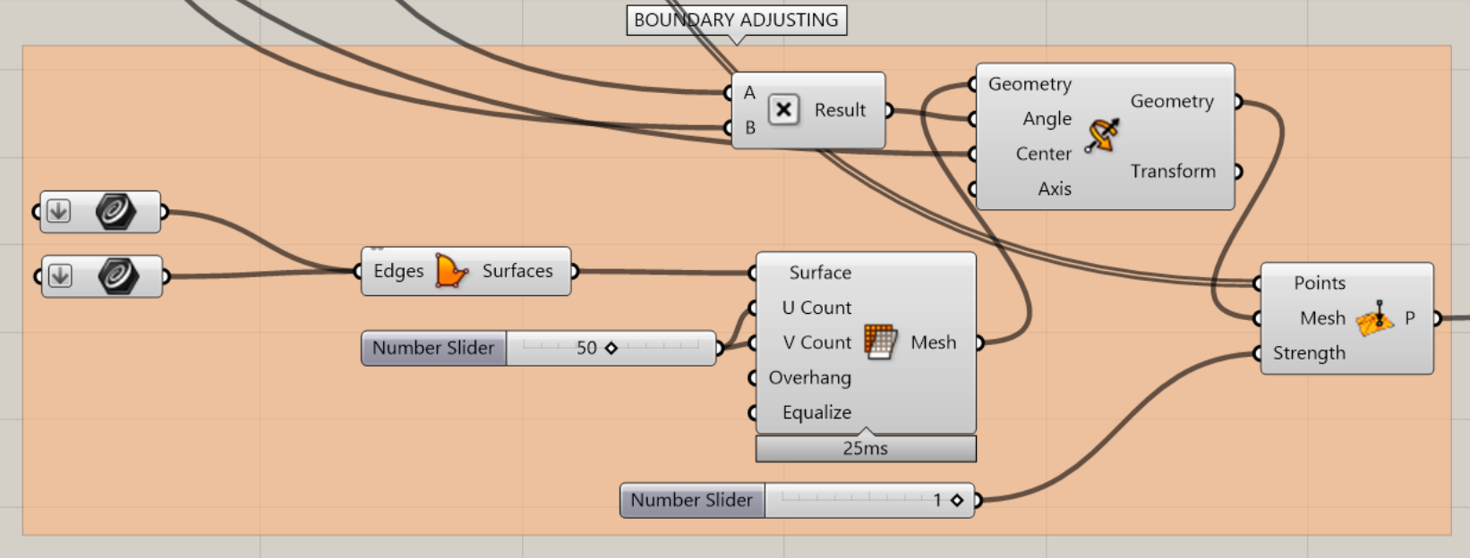
Due to Graph Mapper being dependant on the start point of the curve the initial curve had to be adjusted so that it curves to fit the BOUNDARY ADJUSTING mesh area. To achieve that Seam command had to be incorporated to alter the initial curve beginning.
In BOUNDARY ADJUSTING the boundary has been rotated using the multiplication of stair angle and Counter from the ITERATIONS loop system.
But the problem arrived with generating the first curve.
4.2.5) TRIAL 4 – altering the size o the inner boundary curve with the script from the TRAIL 3
As in TRAIL 1, if any geometry is altered it is the last sections and does not deliver the desired outcome.
It has been decided that the process of incorporating stairs to the 3D cover would be best done by altering individual sections in Rhino to fit the stair print without breaking the consecutive loft of the structure and such manipulation would be best done after advising on the project manufacturing practice.
- Creating PLATFORM and OPENING
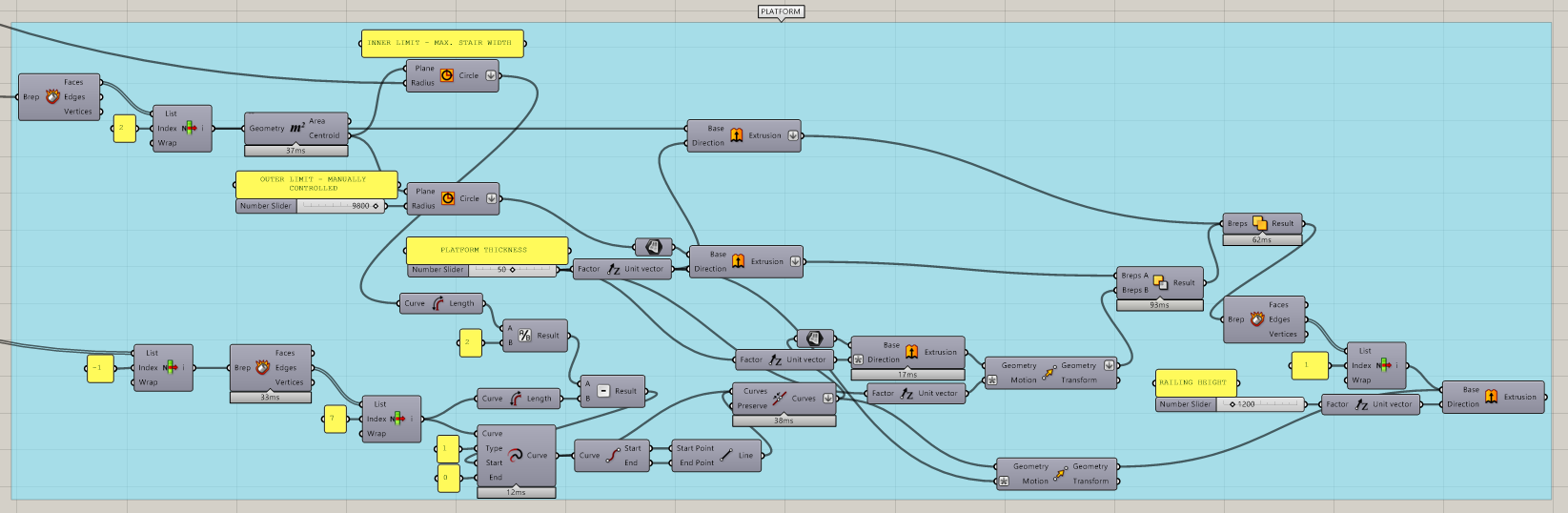
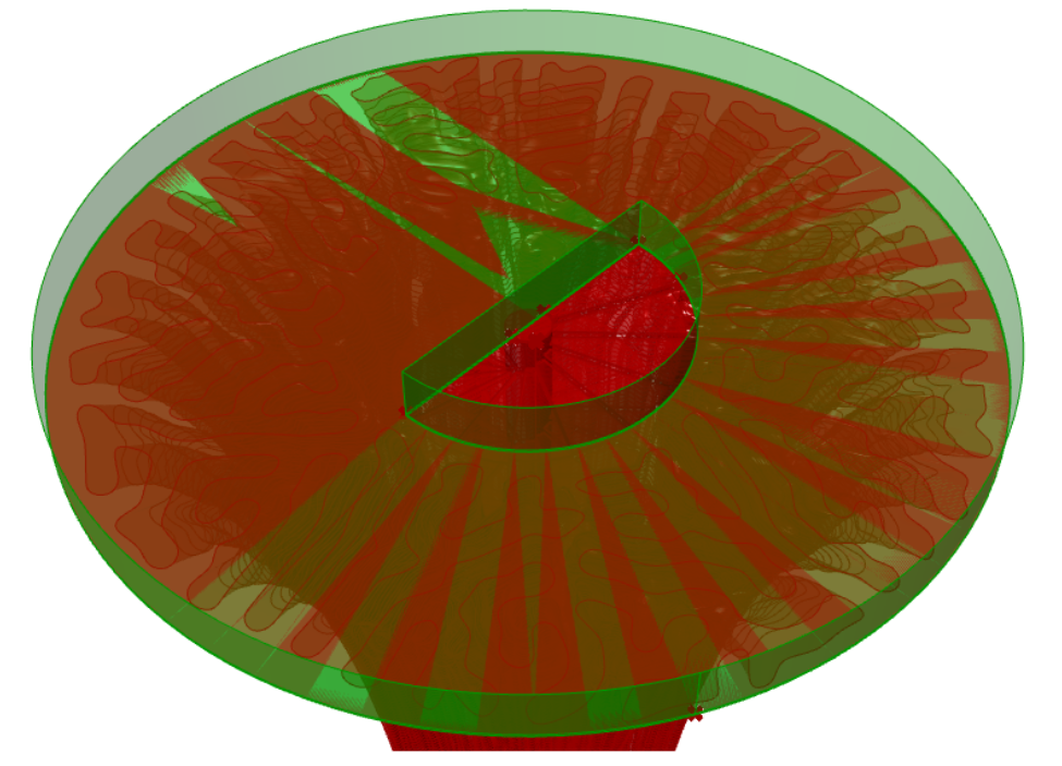
5.1) Creating PLATFORM
There could be many types and design options for the platform, but for this tutorial I chose one based on inner and outer circular limits dictated by the stairs and structure final width taking into the consideration circulation of the people and incorporating the column into the design.
We take the created COLUMN and use Deconstruct Brep. We are aiming to extract the top circular cap which we access with List Item. We find the Geometry Centroid using Area command and creating 2 Circles from the newly found point. One circle for INNER LIMIT dictated by Max. STAIR WIDTH and second circle for OUTER LIMIT which has not been parametrically scripted, but could be using a command Bounding Box and later calculation of the edge length and using half of the value possibly with additional surplus for a radius input of the created circle. Simple Extrusion in ´z´direction of the OUTER LIMIT surface of the circle along with a COLUMN top cap will make for a base to extract other Brep openings from.
As for the opening we need to work with the top stair (last created stair) as we want our opening to be parametrically associated with the last stair entering the platform, which is accessed with List Item with -1 index and deconstructed in order to access the top curved Edge of the Brep, which is later extended using command Extend Curve by calculated length using simple Grasshopper math commands giving us a desired number to extend the curve to match the half length of the INNER LIMIT circle. By creating a Line form its End Points we close the geometry and can use Join Curves in order to create Closed Planar Curve. Later extrusions and Move manipulations with adjusted expressions give for a more optimal geometry rations for Solid Difference command.
Railing of 1200mm has also been added along the platform simply extruding selected curves.
CONCLUSION
The kale lookout tower needs a better understanding in terms of manufacturing to continue on the development of the entrance to the lookout tower and a further elaboration on STEP 4 TRIALS. The tutorial hopes to serve as an inspiration for a development of other lookout towers inspired by nature. The script itself has been divided into groups and consists of parts that can be reused or altered for any kind of projects. All Rhino data have been internalised.
FILES