Bus stop and Data tree
The files of the project: Bus_Stop_Ghp Bus_Stop_Rhino
Steps of the construction:
- We define the lines which will determine the surface of our bus stop
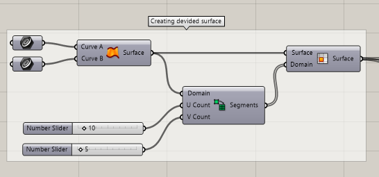
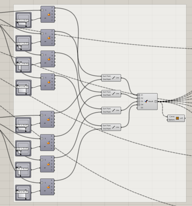
- After defining the surface, we divide it into smaller parts. At this tutorial I made a 10×5 division The division is made by the “Isotrim” component. The number of surfaces is defined with the “Divide domain” component
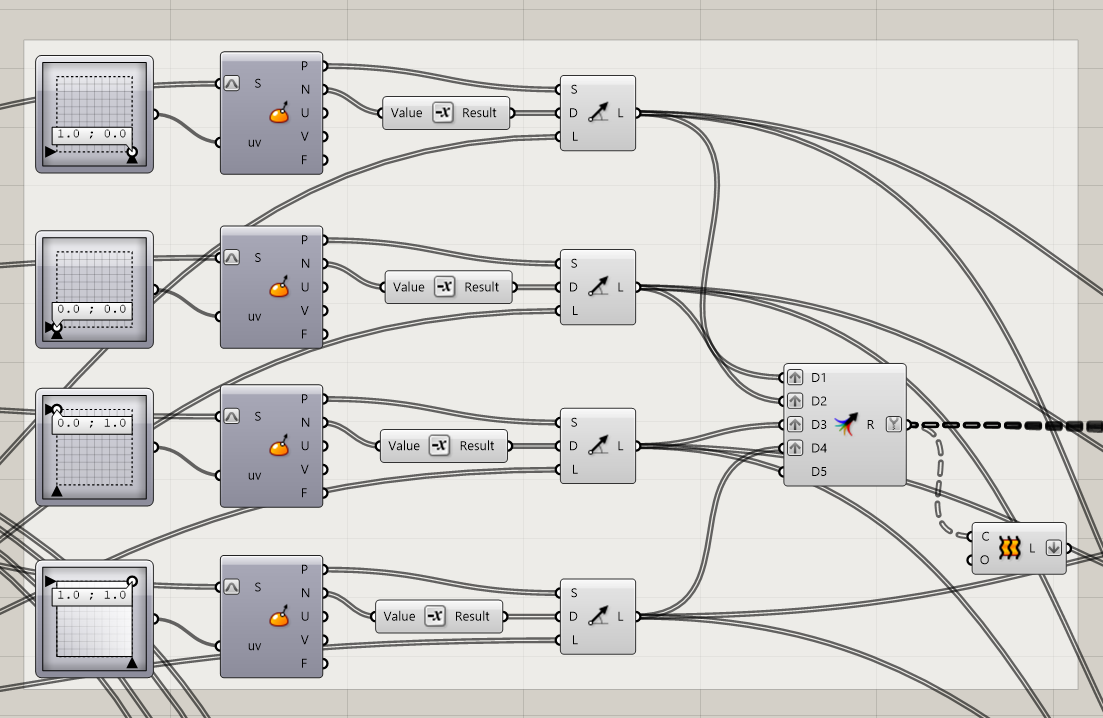
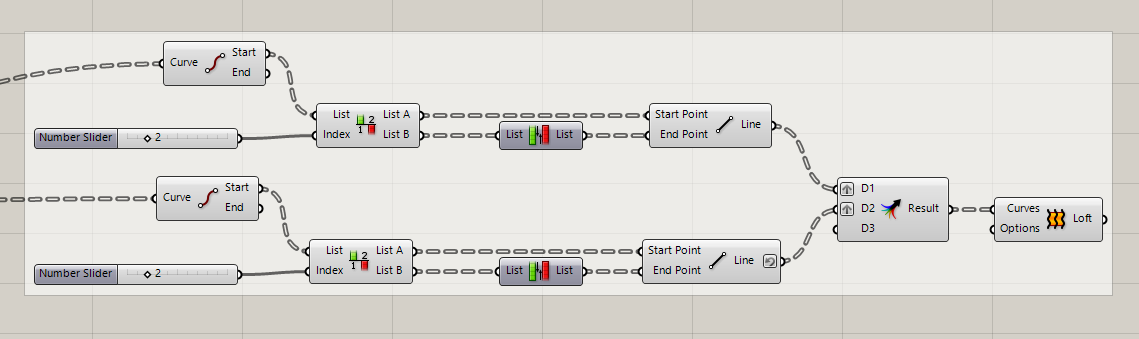
- After we defined the surfaces, we select the outlines of the big boxes. The start points of the lines points are selected with the “Evaluate Surface” component. To show to the component which point are we talking about, we will use tan “MD Slider” component. After we defined the point, wit the “Line SDL” component we create the lines. The start point will be the point which we defined earlier, the direction will be the negative value of the normal vector of the surface, because we want to create the line to the other side of the surface.
- Now we still have a missing value which is the length of the lines.
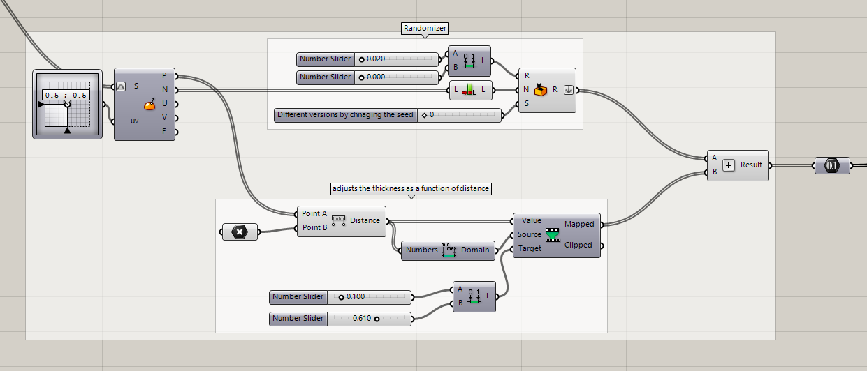
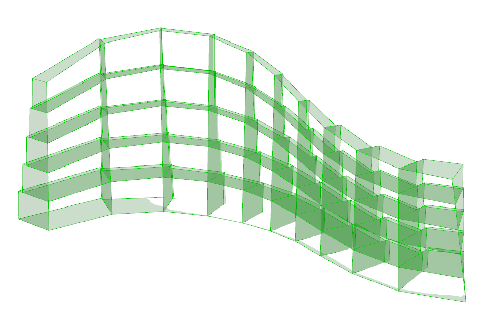
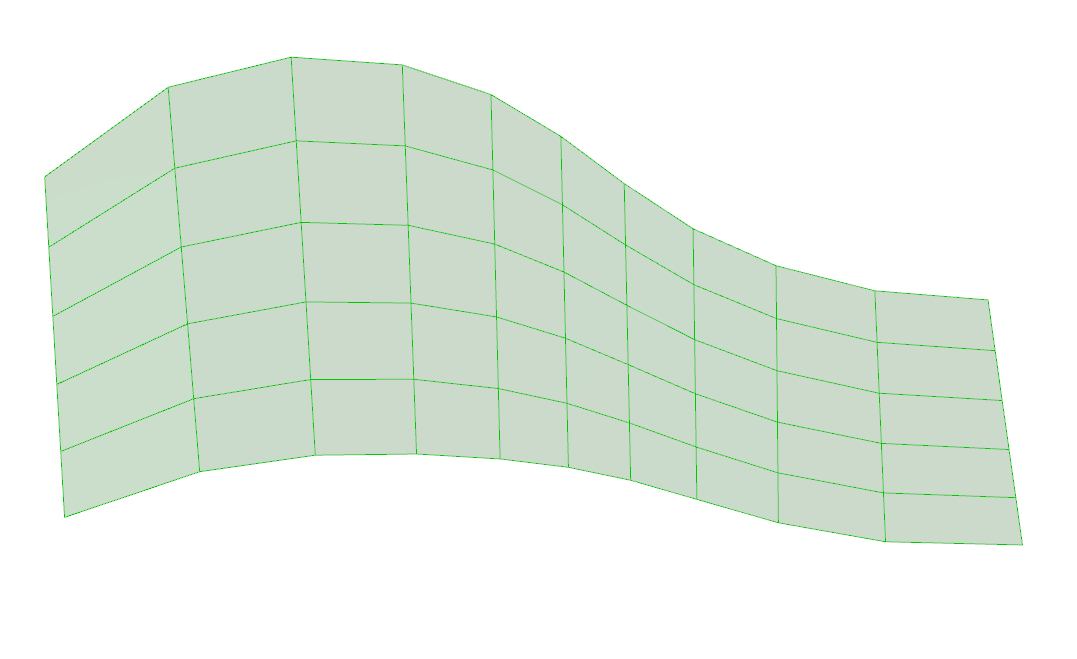
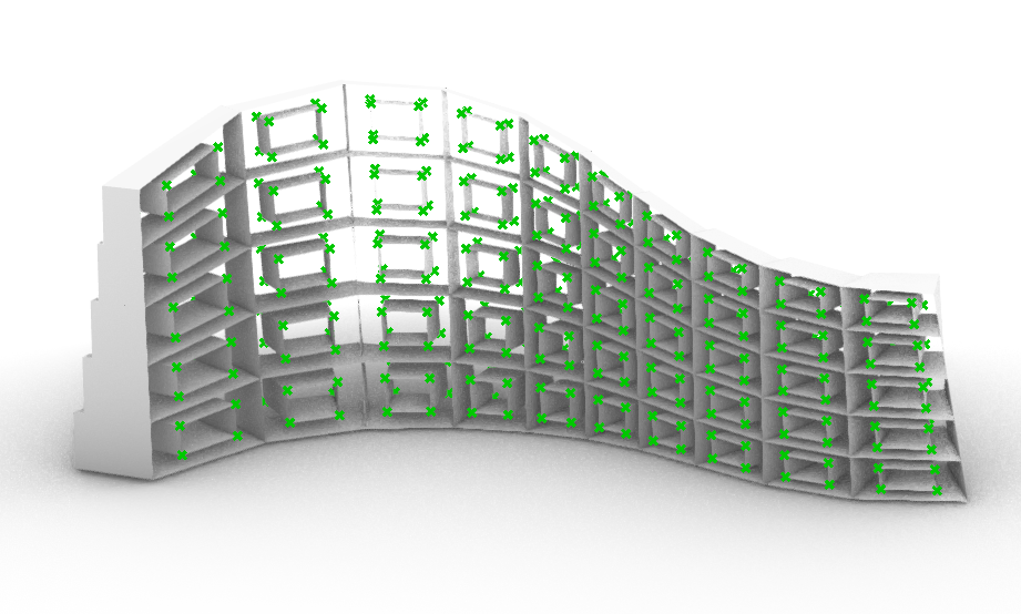
- To define the length, we will use a point as a reference to make bigger and smaller boxes. So first we will use again the “Evaluate Surface component” and the “MD Slider” component to select the middle point of the surfaces. This will be our first point. Then we create another point, not too far from the surface. This will be our reference point. We measure the distance between the points and with the “Remap”, “Bounds” and “Construct domain” component we determine the remapped value of the distances. I choose the 0.1 and the 0.61 as reference values for the remap command. To be the length a bit more random, we add this value with a random generated number between 0 and 0.02. Do not forget, we are talking now in meters. When we finished, our preview image should look like this:
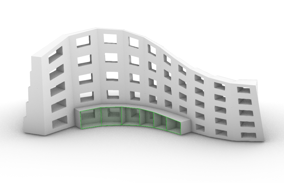
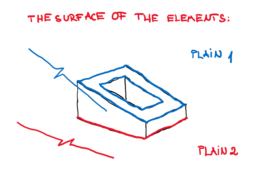
- So now we have the big boxes. Let’s create the smaller ones. What is very important now is that the start and the end points of the smaller boxes must be on the same surface as the start and the end points of the bigger boxes. If we do like this, then we will have two flat surfaces and we will be able to print out the elements.
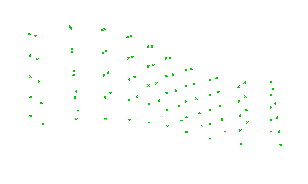
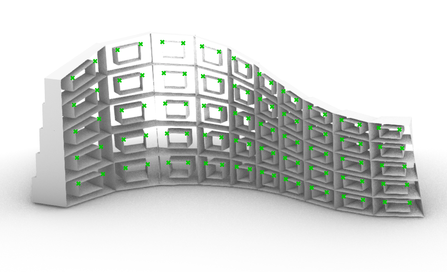
- To create the start points which will determine the small boxes, first we select all the points which determine the big boxes. The selection should look like this:
- Then we select just the starter points from these (which are on the same plain) and we create lines with the “Lines” command. Because every surface has a left and a right line, we must select both lines, to be able to create the surface. We combine the left and the right lines with the “Merge” command. Don’t forget to use the graft element at the Merge component. This is very important. If we would not use the graft component, then we would have only a list of lines and not pairs of lines. So, don’t forget to use the “graft”.
- With this method, we create also the front surfaces. The lines and the surfaces now looks like this:
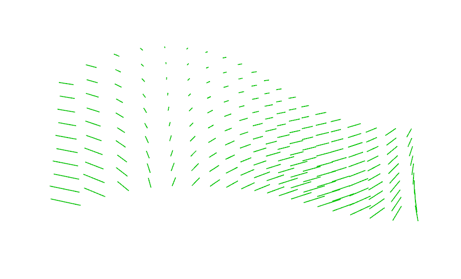
- Now to select the right points on the surfaces we will use the same method what we used to create the big boxes. With the “Evaluate surface” we select the point what we define with the “MD Slider”. I wanted to make boxes with 25 cm bezel.
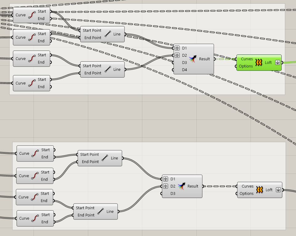
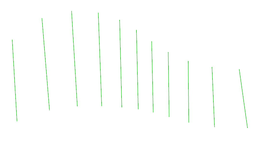
- Now we got the lines to create the boxes. The lines should look like this:
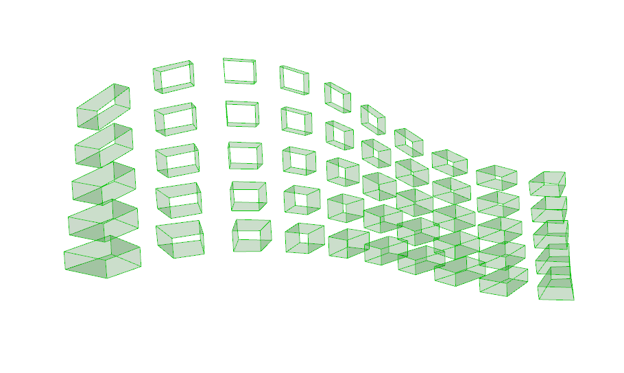
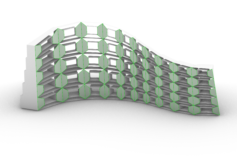
- With the Loft command, we create the boxes:
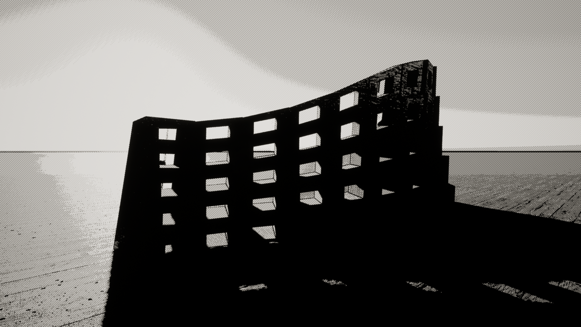
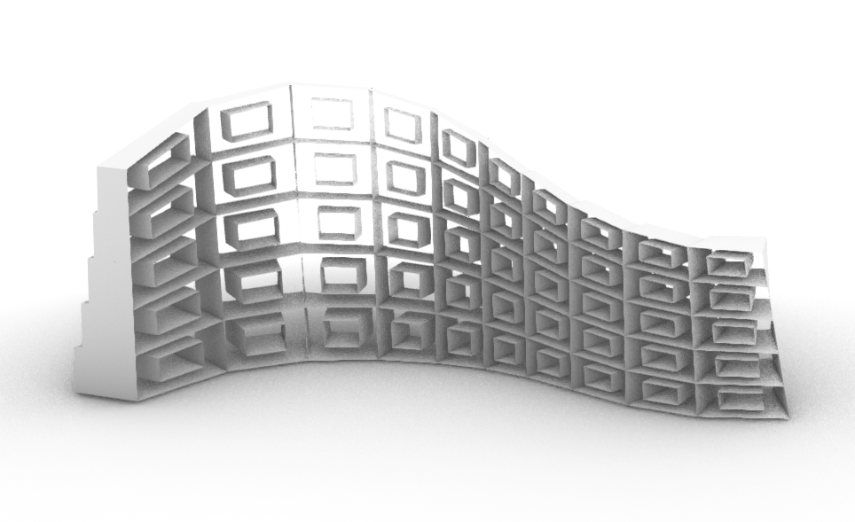
- If we “bake” the boxes, we should have a result something like this. Of course, the form is depending of how you formed the lines at the start. I tried to make it more interesting, so I waved the lines a bit.
- Now it comes the harder part. We must make the connections between the boxes. To make the vertical elements on one side, I used the following:
- Wit this method, first I choose all the starter and end points from the small boxes.
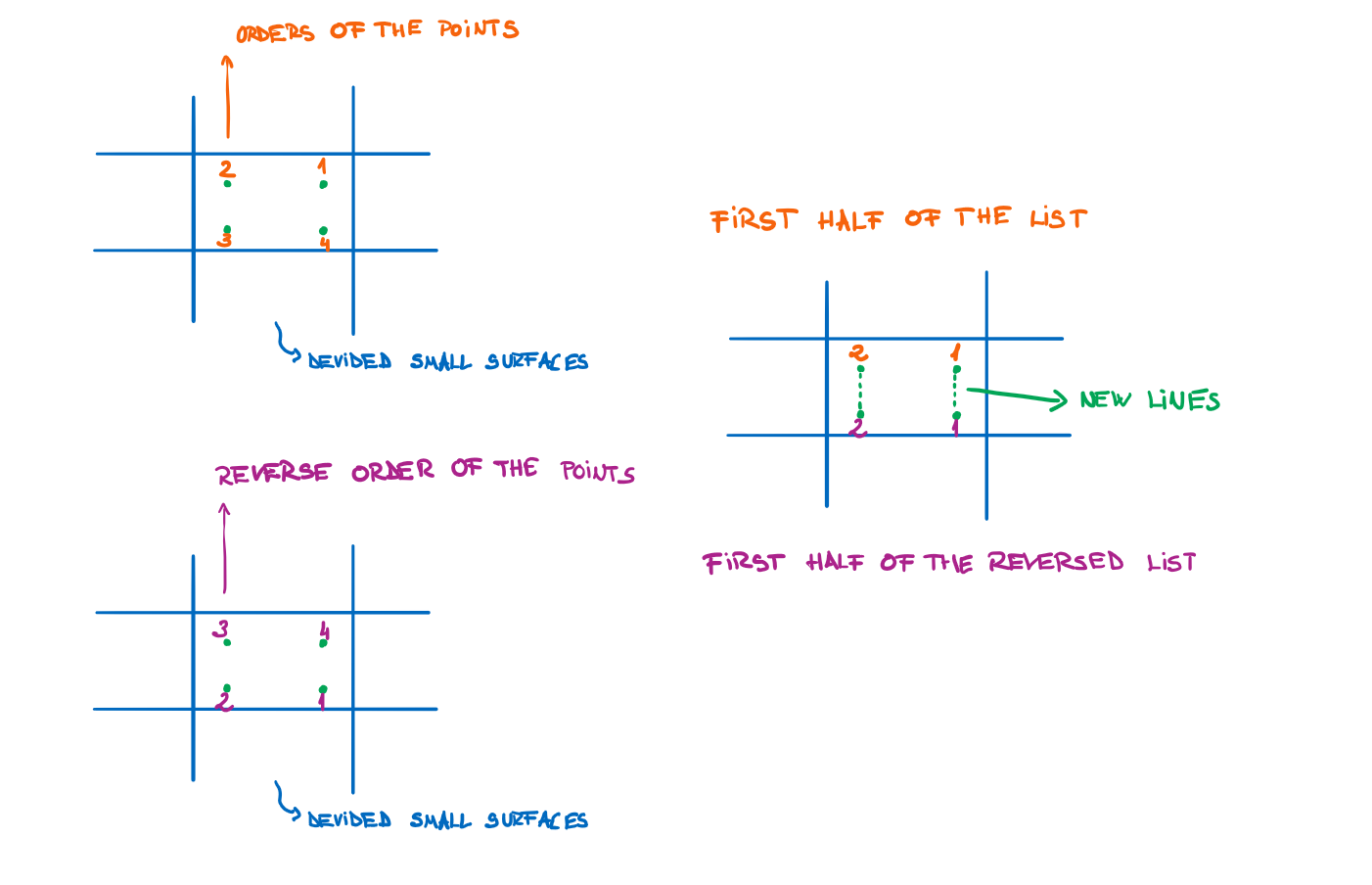
- Then, I devided the lines into two part. I could make this, because the lines are in a list, and the first part contains the points on the one side and the second part contains points from the other side.
- After I choosed the points from one side, to make the lines, I have to select the start and the end points of the lines. The end points will be the followings:
- Why should I use the reverse list to get the end points? It is because how the data tree looks like. To explain a bit, here is the following sketch about how the data tree works in my case:
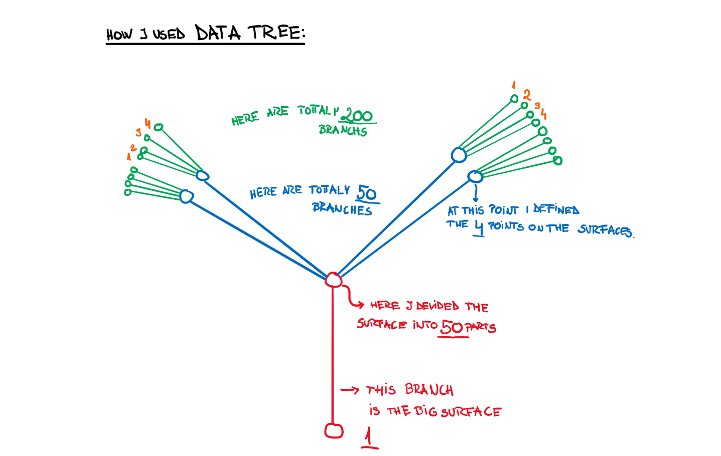

- With this method, we will create the outer lines and we merge the data with the “Merge” command. Because these lines are now with the right pair, we can use the “Loft” component to create the surfaces. The method, how to create the other parts od the surface, is the same. First, we must find the start and then the end points, we must put them into the right order and then we create the lines. We merge the lines (every line with their correct pair) and then with the loft command we create the surfaces.
- To create the benches, we will use a bit different method.
- First, we search for the points which will determine our bench. Then, we create the lines from that start points. Which we have choose, with the direction of the normal vector. The length is a number defined by us, I used 30 cm.
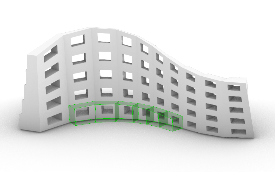
- At the end, we create the front surface of the bench.