
I was asked by a friend of mine to help him design a facade for his project in Studio work. He was designing ŠKODA exhebition grounds for mr. Hájek and co.
First of, we needed to find common “grounds” about the facade. After many tries, decidion was made. It would have two layers, outer being made of steel pipes, connected with ball joints, and inner made of glass. These two layers were to be connected with the same pipes, that were used for outer layer.
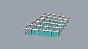
I started with constructing a domain, which allowed me to trim the surface with Isotrim. This way it should work with boxes too.
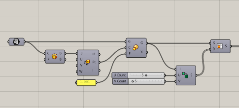
One of the most important parts in this version was Surface Points with Point outcome being flattened. Those points were used as
a) centers of ball joints
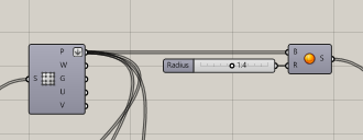
b) start points of pipes connecting layers
c) defining points for second layer movement
d) defining points for end points of connecting pipes (Plane closest point component)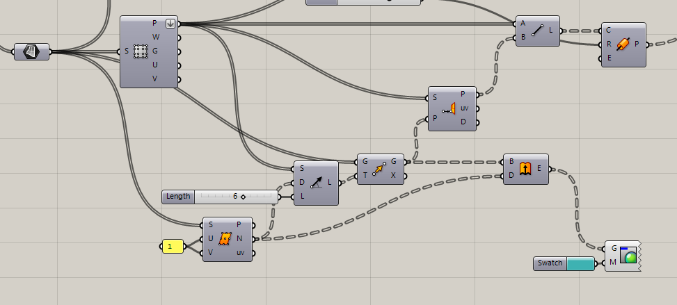
Last but not least, Brep Edges component served as perfect center lines for pipes in outer layer.
Note: Glass planes were meant to be separated with rectangle steel profiles, but my PC almost exploded whilst processing those.
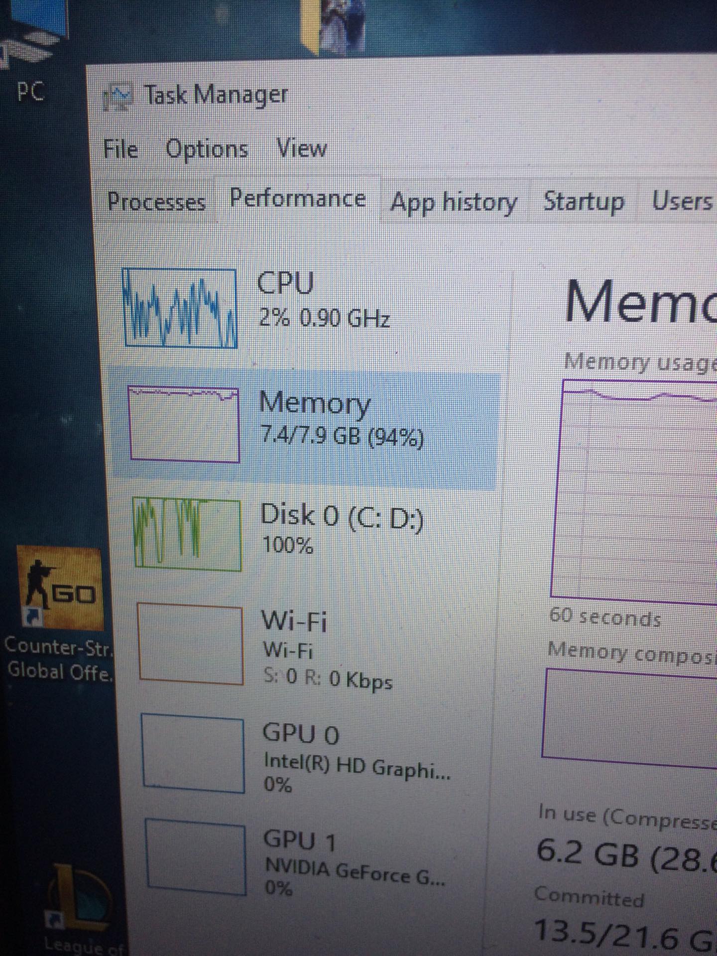 ¯\_(ツ)_/¯oops
Then I received his model, which was both mess and mesh. First step was converting those meshes(there were multiple, because my friend has just cut the model in order to 3D print it) into surfaces with a simple script, which deconstructs mesh into defining points, lists them with their faces and creates a surface out of them(4pt Surface). Second step was baking it in.

![jakub skoda model (36 MB) - Rhinoceros 6 Commercial - [Perspective] 2_18_2020 7_46_41 AM](http://scripting.molab.eu/wp-content/uploads/2020/02/jakub-skoda-model-36-MB-Rhinoceros-6-Commercial-Perspective-2_18_2020-7_46_41-AM2.png)
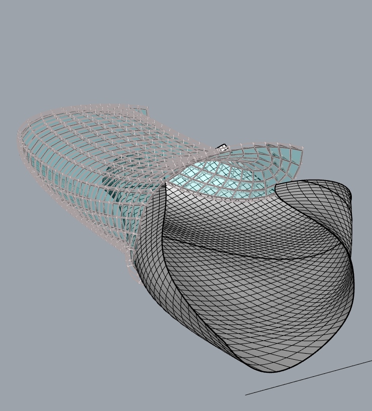
After I connected all small surfaces created by previous script into one big surface with Rhino commands Contour and Patch Surface, I had to simplify(straighten etc.) this surface a lot, so the Ghop file would apply smoothly. Then I realised… It wouldnt work, due to me being dumb and writing the script the way that the outer layer would overlap with model and inner layer wouldnt be visible without deleting the model itself(EDIT: Now I realise, I can just hide it in Rhino) . Still I chose to rewrite that script, simplifying it in the process, switching which layer is main and which one is only Grasshopper generated. With that, script was stripped a bit, making it harder for me to fry PC(Spoiler alert: I still managed to do it)
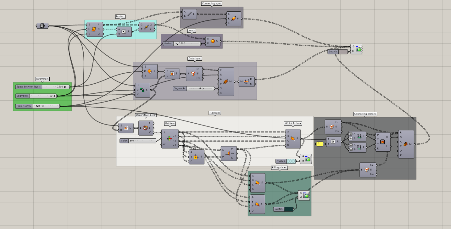
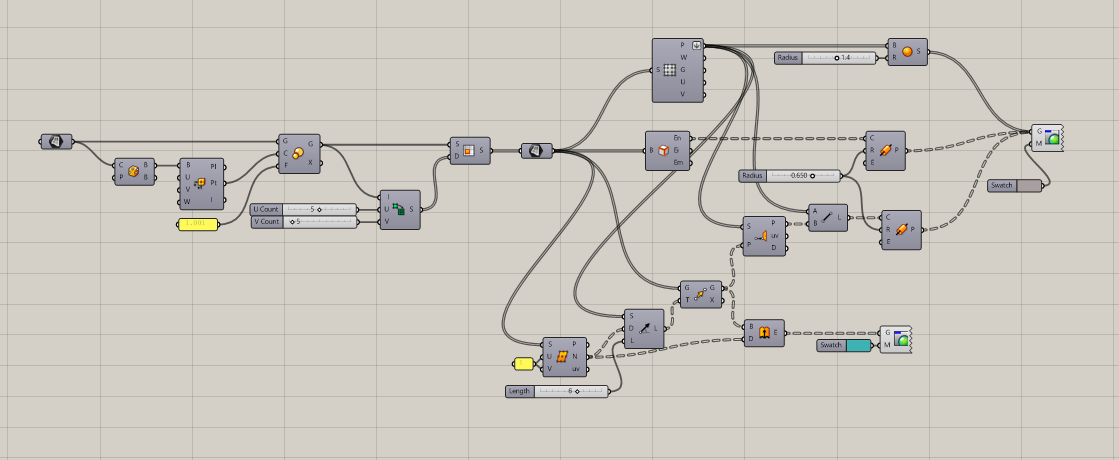
Using Divide Surface not only gave me normals for layer movement, but also worked the same way as Surface Points in previous version.
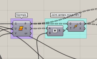
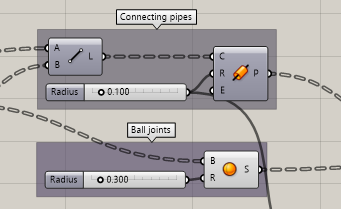
With this being done, both connecting pipes and ball joints were really simple to do. Just a recap, starting points for connecting pipes are points from Divide Surface, end points are the same points after the move component being applied.
Outer layer was created with Offset Surface, trimmed with Isotrim and Domain has the same parameter as Divide Surface(now 20). Brep Edges kept his job as center lines for mesh pipes of outer layer, mesh unite then leads into Preview component to keep those pipes same as other types. Distance parameter of Offset Surface has same slider as Multiplication in Joint centers movement part.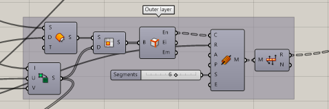
Due to the model being shaped the way it is, creating glass panes would be extremly expensive. So I had to straighten them, using The Smithsonian Institution roof principe to planarize glass quads. This deconstructs original surface and uses its verticles, listing them with 4 exports, takes 3 of them and uses them to create plane for this segment and 4th export being used to search for closest point on previously mentioned plane.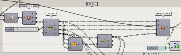
Those last points are also used to create filling triangles between straightened glass and original surface. one of each of these 4(3) Point Surface combonents creates these fillings in different direction.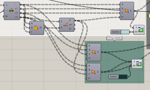
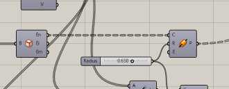
To complete this facade, I decided that square profiles would be nice to separate glass panes and filling triangles, Breping them to get their edges and using Mesh Sweep to relpicate square profile on them. Square was created with range component. Without that move, I wouldnt be able to define it from a center point(edges of panes). Square lenght has same parameter as pipe radius, just doubled.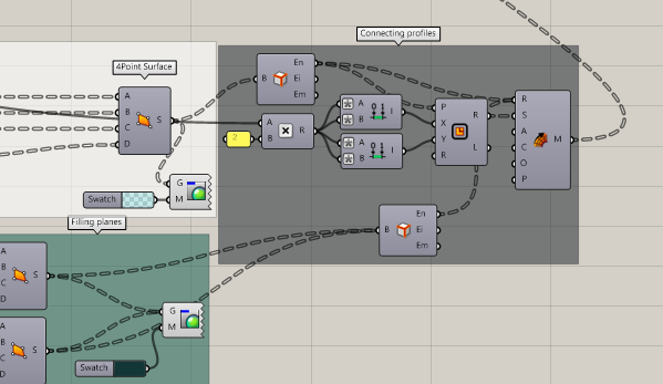
Sripts:
1st try: semesrtalka ghop
Final verion:SkodaMuseumGhop, Model Geometry
Inspiration: Smithonian Institution https://inhabitat.com/the-smithsonians-vaulted-canopy-brings-nature-and-light-inside/smithsonian-daytime/
Tutorial for Mesh=>Surface conversion: https://www.youtube.com/watch?v=scQGLhSBakI