HEXAGONAL PAVILION
The point of this script is to build a pavilion using a construction method I came up with. It consists simply of multiple hexagonal pieces that are mounted together using vertical rods.
The reason behind the shape of the pieces is that the hexagon allows tessellation*, without recurring to other shapes. The square or triangle also allow this, but the end result would be something much more rigid, since with the hexagon the structure can grow in 6 directions, and with a square only in 4.
Another design choice was making the cylinders taller than the center of the piece. The intension is that the structure has some transparency, and with luck getting some cool light/shadow effects.
(*tessellation: an arrangement of shapes closely fitted together, especially of polygons in a repeated pattern without gaps or overlapping.)
As for the shape of the pavilion itself, I decided to base it on an hexagon as well. This way the individual pieces look somewhat oriented within the overall shape, and create some nice patterns on the elevations. This was only a choice to try the script, as it would work with any other shape. On the end of the tutorial some other shapes are shown.
This is the tutorial:
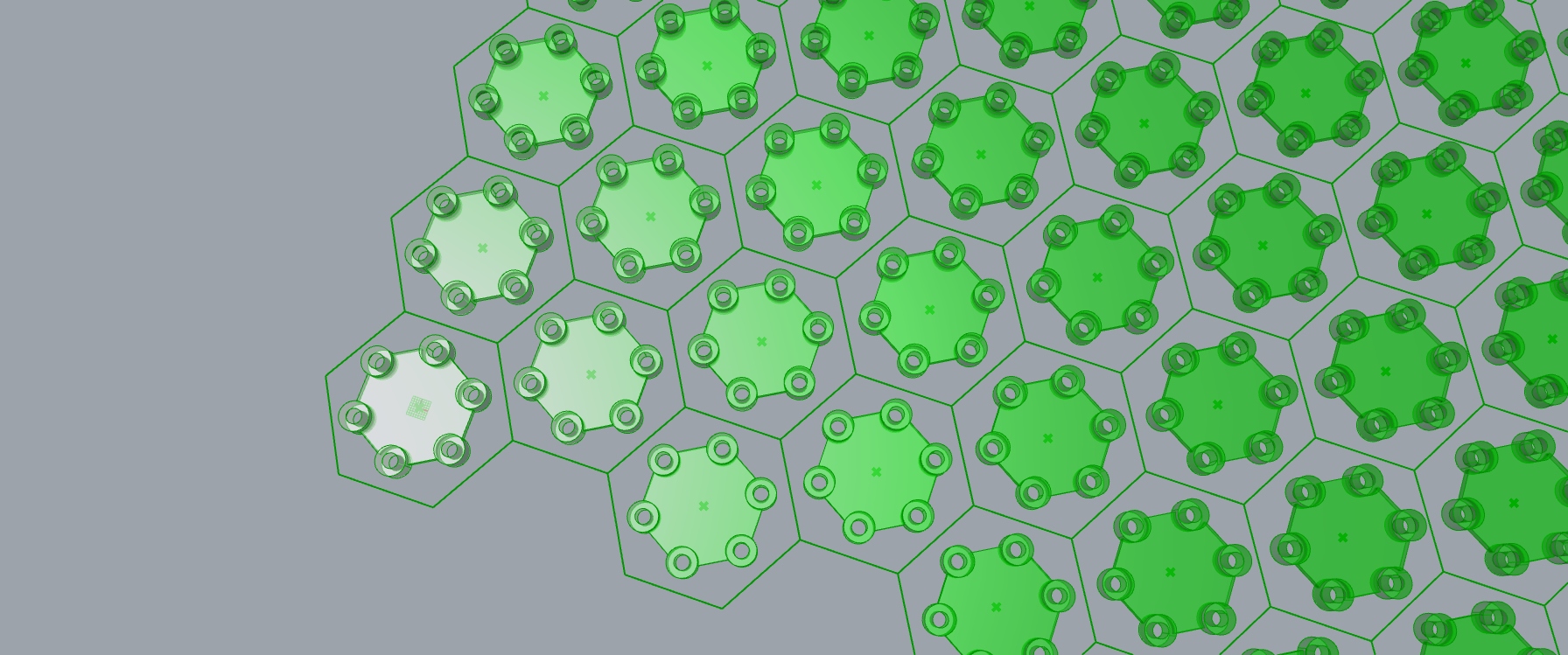
1. HEXAGONAL PIECE
The first step is to design the hexagonal piece, that will later be used for the pavilion structure. I split this step into 2 parts: The “Cylinders” and the “Inner Piece”.
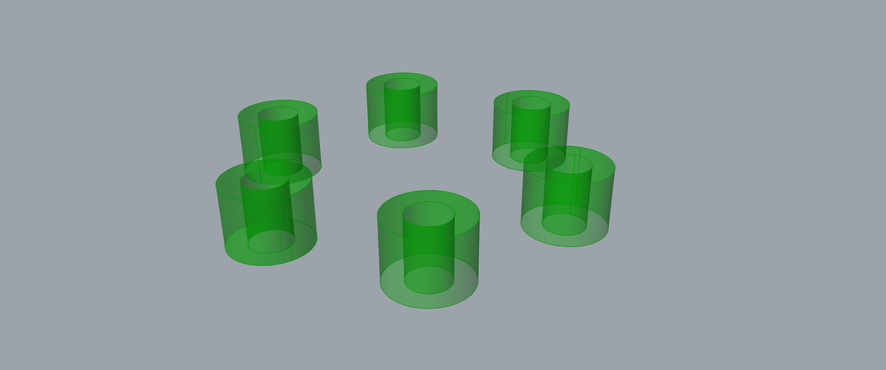
a) CYLINDERS
It starts with dividing a circle into 24 parts, to get the distance between two consecutive points, for the outer cylinder radius. For the inner cylinder the same Base is used, and the radius is arbitrary (I chose 2cm). This radius will be the sabe for the “Rods”. For the top and base of the cylinder, Brep Edges and Boundary Surfaces are used. Both cylinders, the base and the top are put together into a Brep, which is repeated along the inicial circle 6 times, using Curve Array.
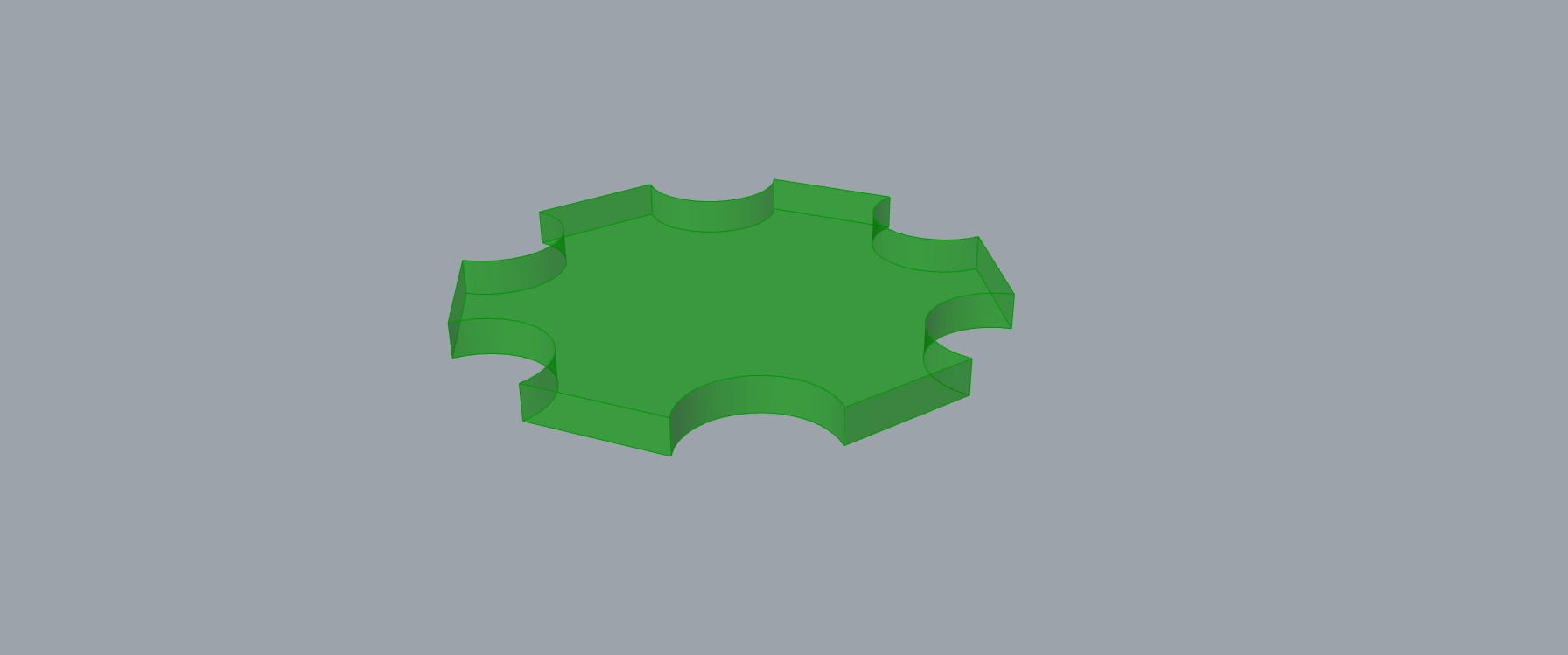
b) INNER PIECE
The same circle is again divided into 24 parts, but this time the points will be filtered with Dispatch and Shift List to create line segments and arcs between them, intercalated. The radius of the outer cylinder is used to offset the initial circle inwards. This new circle is divided into 12 points, that are filtered with Dispatch, and used as a middle point for controlling the arcs. All the segments are joined, turned into a surface, and finally extruded 2cm.
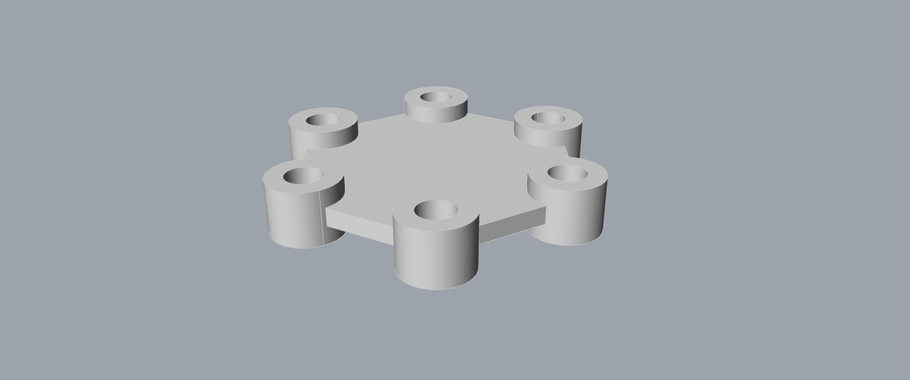
Both parts are put together into one Brep.
2. PAVILION SHAPE
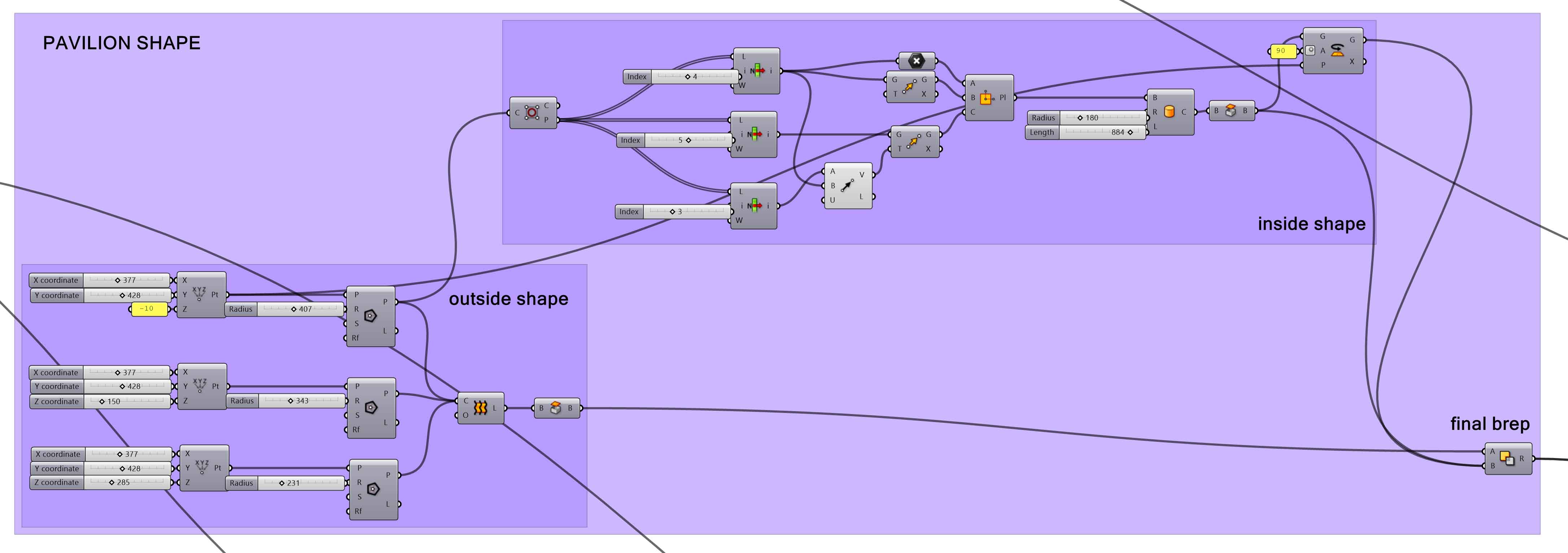

For this “construction method” almost any shape would work, so I won’t go into much detail for how I designed mine. I simply used Loft on three different hexagons with different sizes and heights, and then carved two cylinders for the entrances, using Solid Difference.
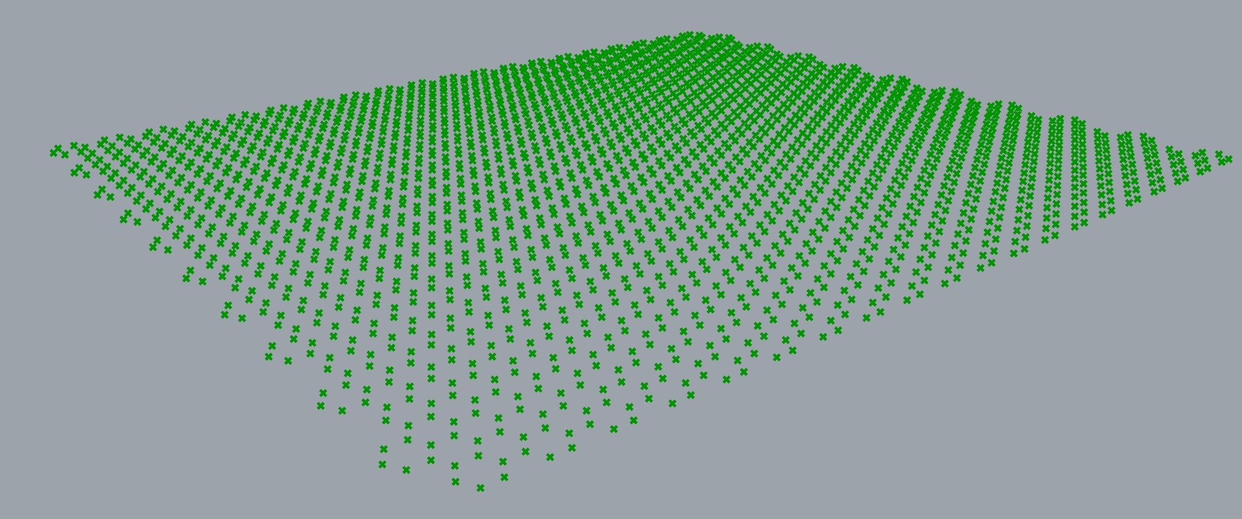
3. POINT GRID

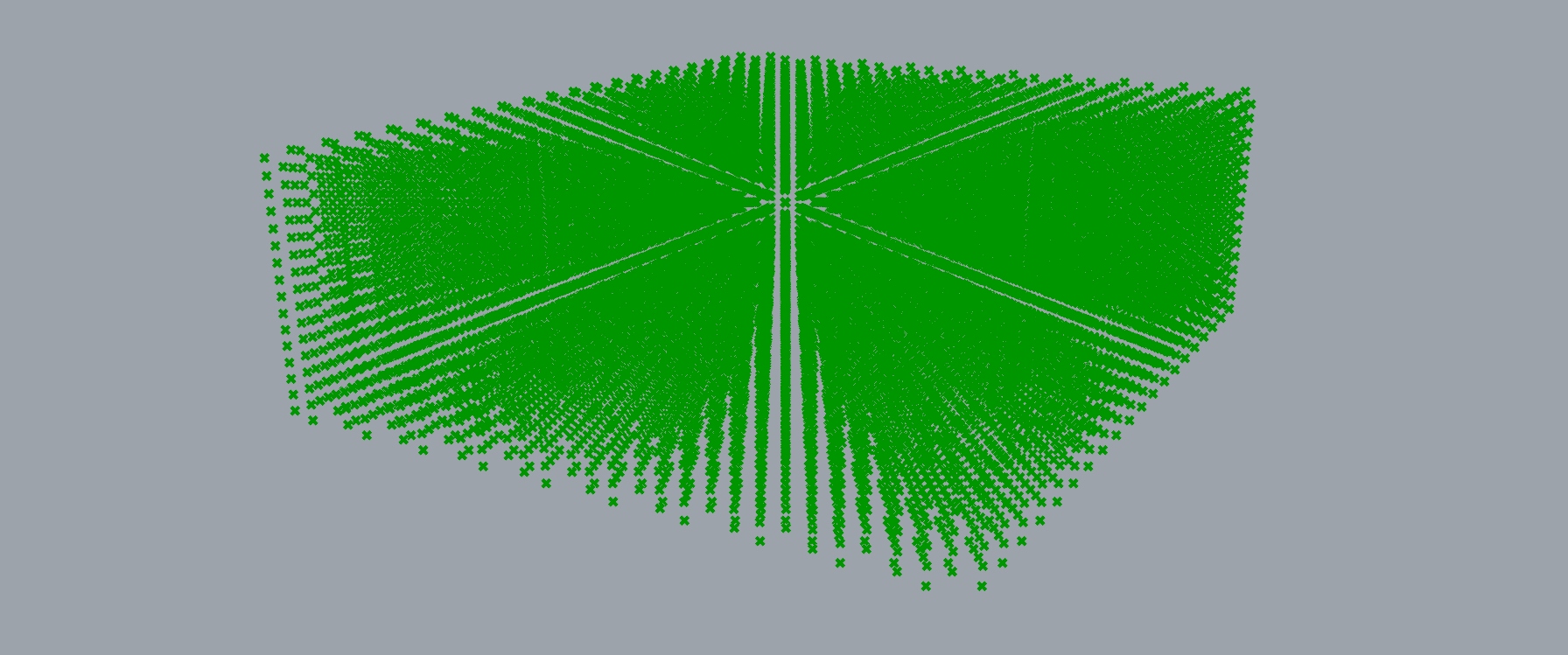
The next step is to create the 3D point grid for the Hexagonal Piece to be applied. This 3D grid is made from repeating vertically three 2D hexagonal grids, which are out of phase.
The first 2D grid is obtained by getting the center points of a hexagonal grid. The size of the hexagons is the radius of the Hexagonal Piece multiplied by 1.73205081. This very specific number is so that there is an empty space the size of a Hexagonal Piece, between each Hexagonal Piece, when they are applied.
The second grid comes from selecting one point from every hexagon in the initial hexagonal grid and moving them up.
The third grid comes from selecting a different point from every hexagon in the initial hexagonal grid and moving them down.
Finally, this pattern of the three grids is copied up 15 times.
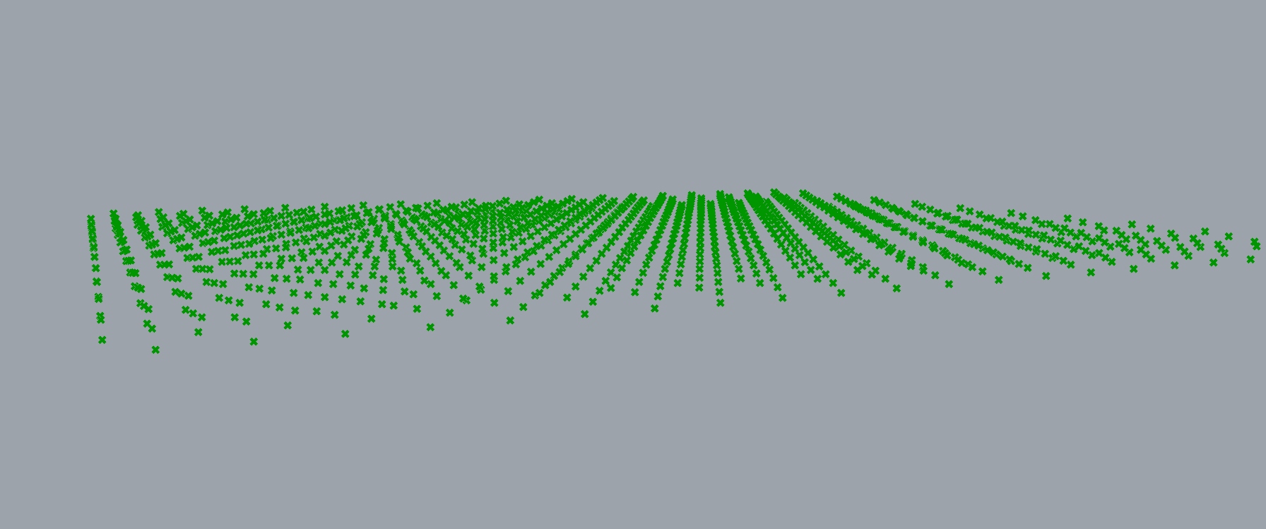
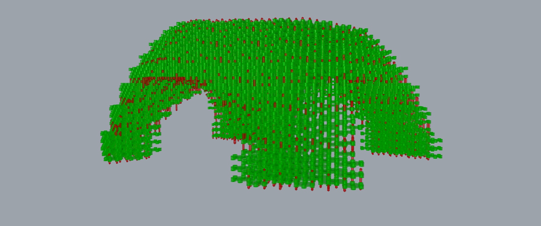
4. FILTERING POINTS and HEXAGONAL PIECE PLACING
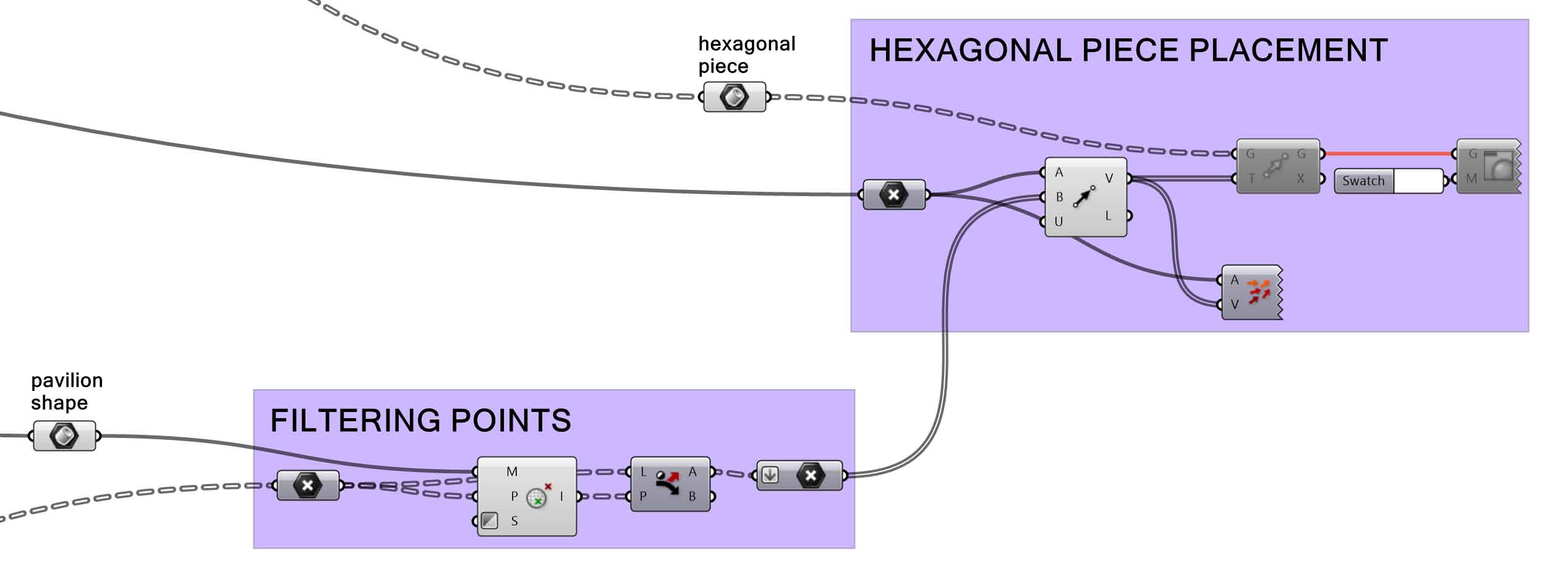
Applying Mesh Inclusion to the Point Grid, using the Pavilion Shape as the Mesh, and afterword Dispatch, only the points inside the Pavilion Shape are kept.
Using Mesh Inclusion was suggested in the forum, after having some trouble with Point In Brep, as it was including one point which was outside of the Brep. Apparently this can happen when some Boolean intersections don’t behave the way they should.
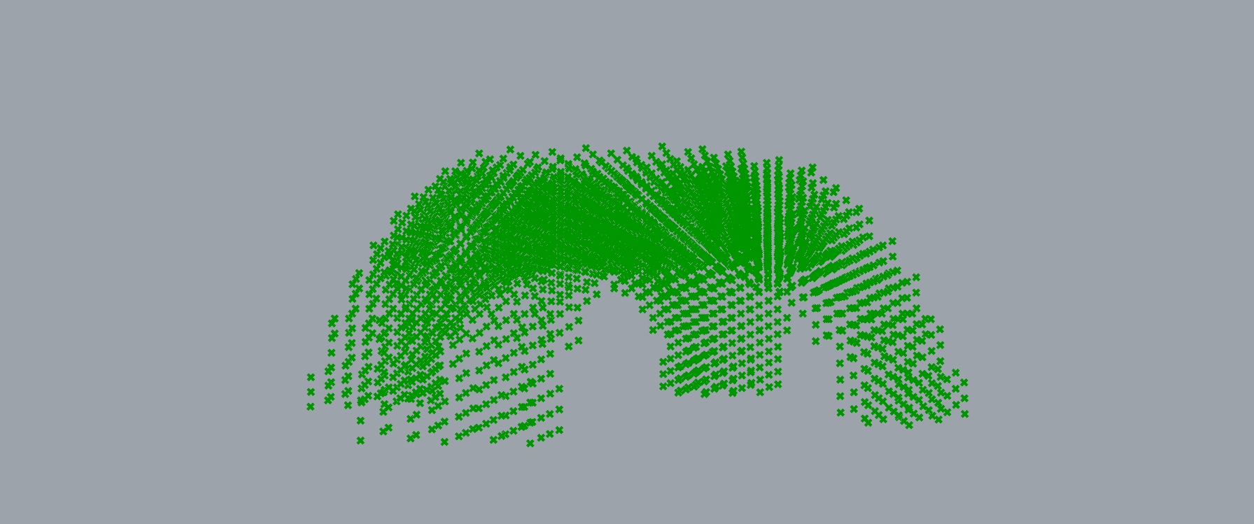
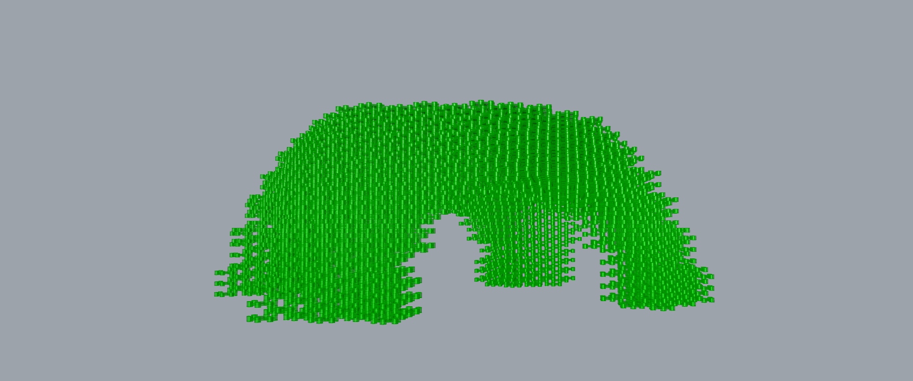
These points are then used to copy and place the Hexagonal Pieces into their final destination.
5. RODS
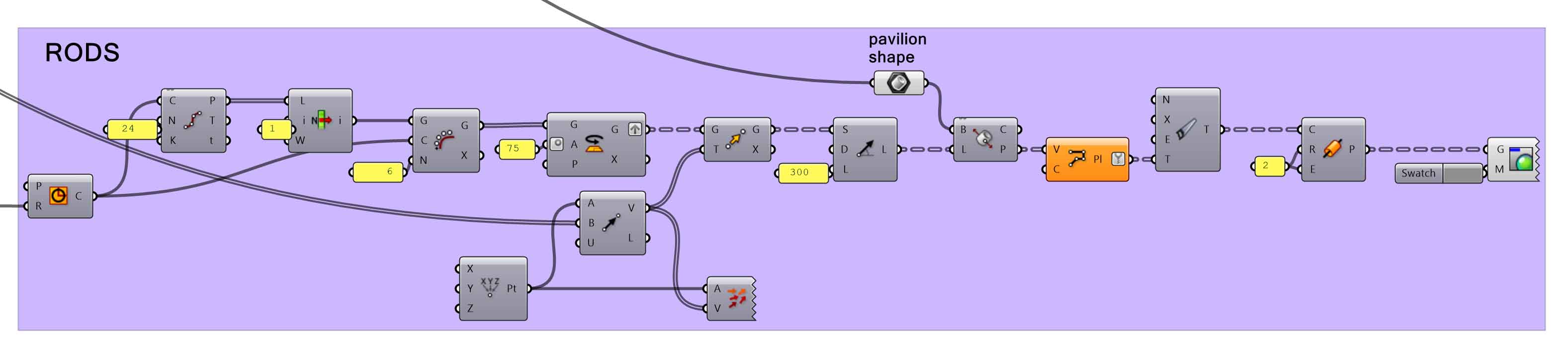
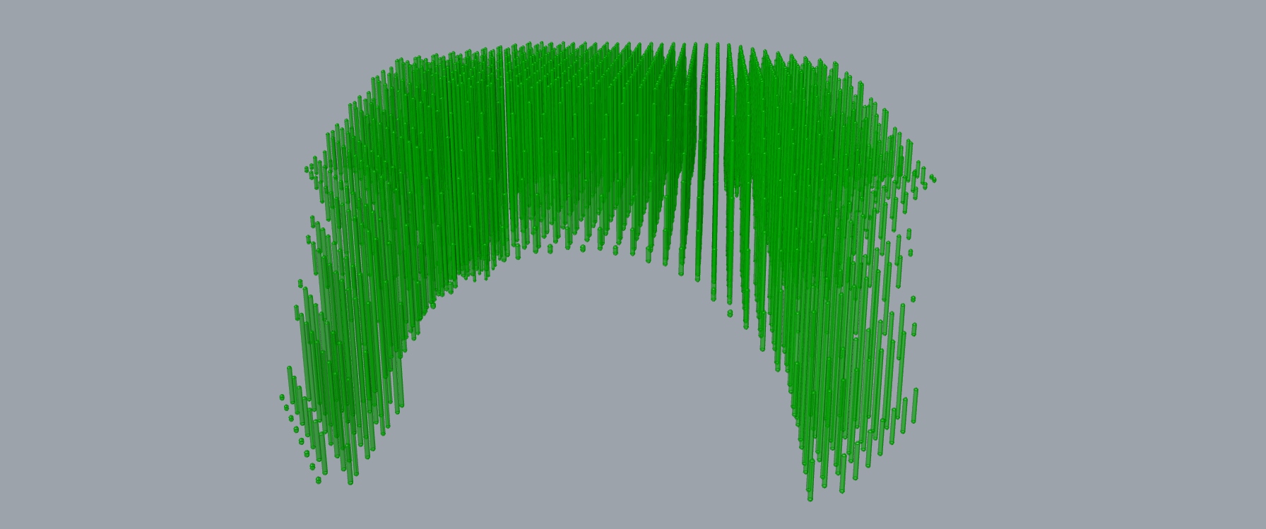
The only things missing in this design are the rods that keep the Hexagonal Pieces together.
For this, a new 2D point grid is made, where each point corresponds to the center point of the base of each rod (these points are also the center points of the cylinders of the hexagonal pieces).
With Line SDL, using every point of this grid as a start point, we get vertical lines that correspond to the rods. Then Brep \ Line gets the intersection points between these vertical lines and the Pavilion Shape. These points are vertices for the new Polylines. Now we have the vertical lines corresponding to the rods, but this time cut to the Pavilion Shape. (After this the Data Tree requires some cleaning with Clean Tree).
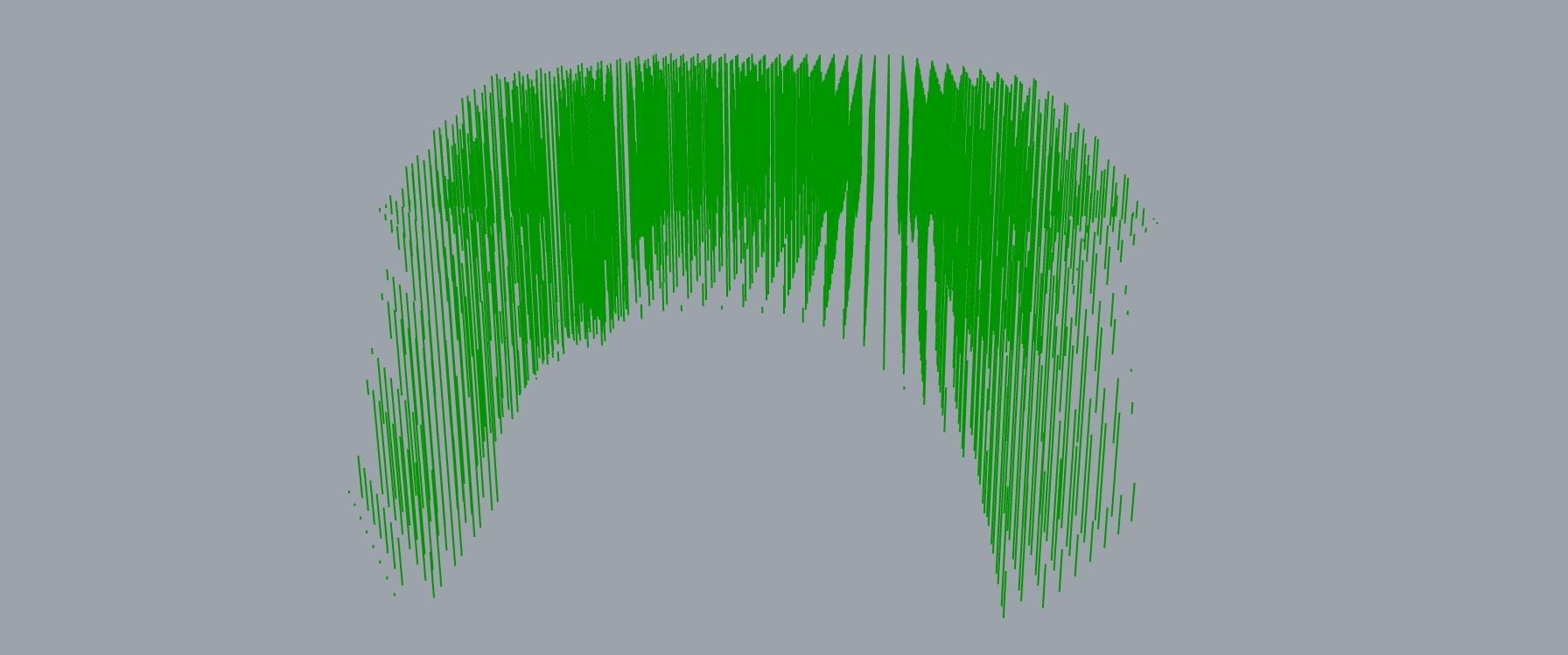
The last step is to simply use Pipe to make the rods, using the previous Polylines as Base Curves.
This is the final result:
Experimenting with other shapes:
This script and construction method could be used to get any kind of shapes and structures, from cave looking pavilions, to simple walls.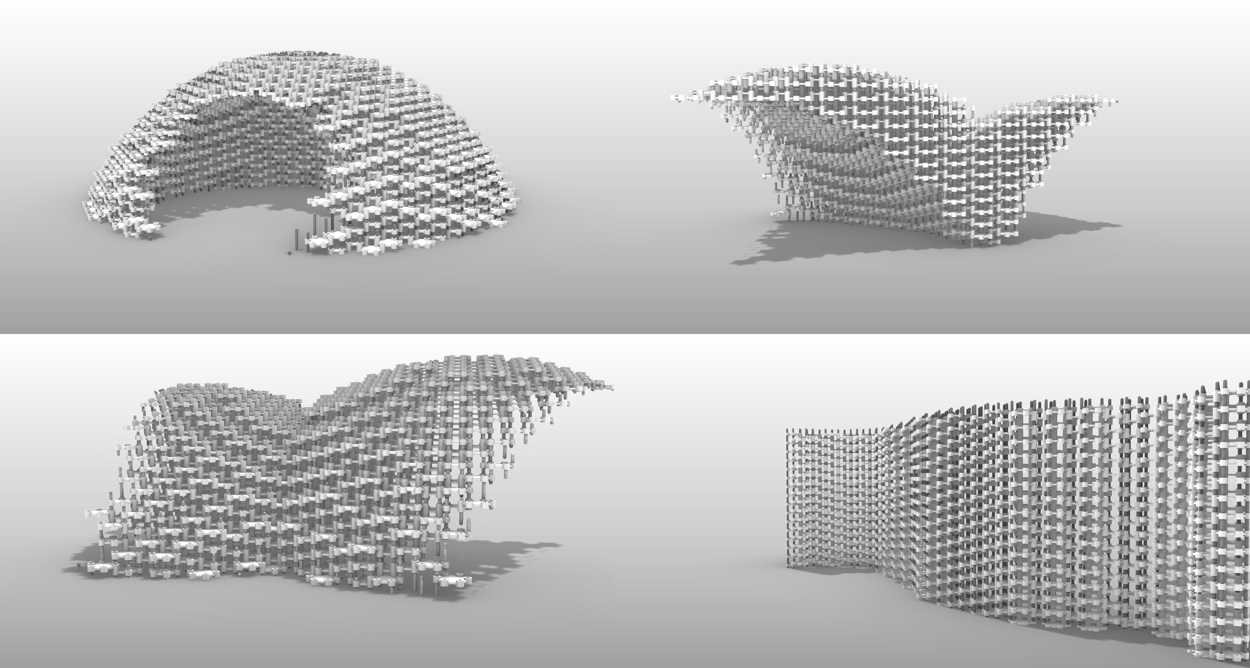
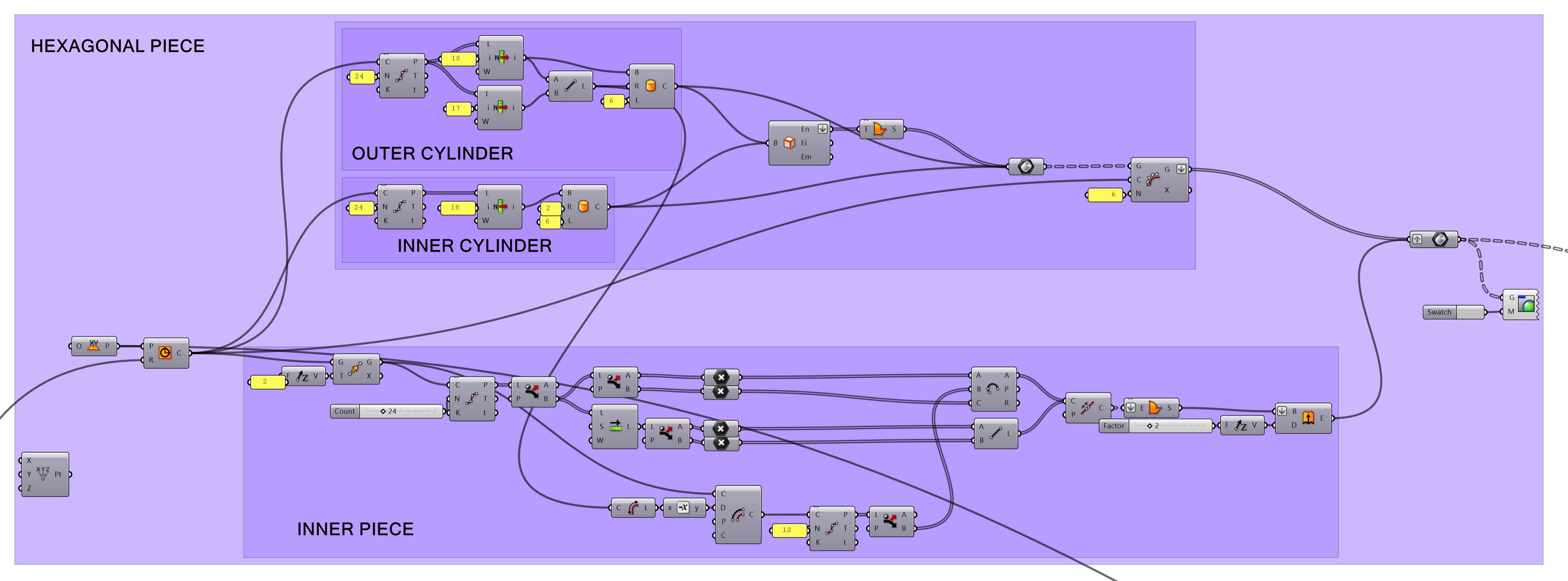
THE SCRIPT