- CODE FILE: FLOATING BAR CODE
- This tutorial aims to create a code that can simulate the mechanical components of a project made out of pistons
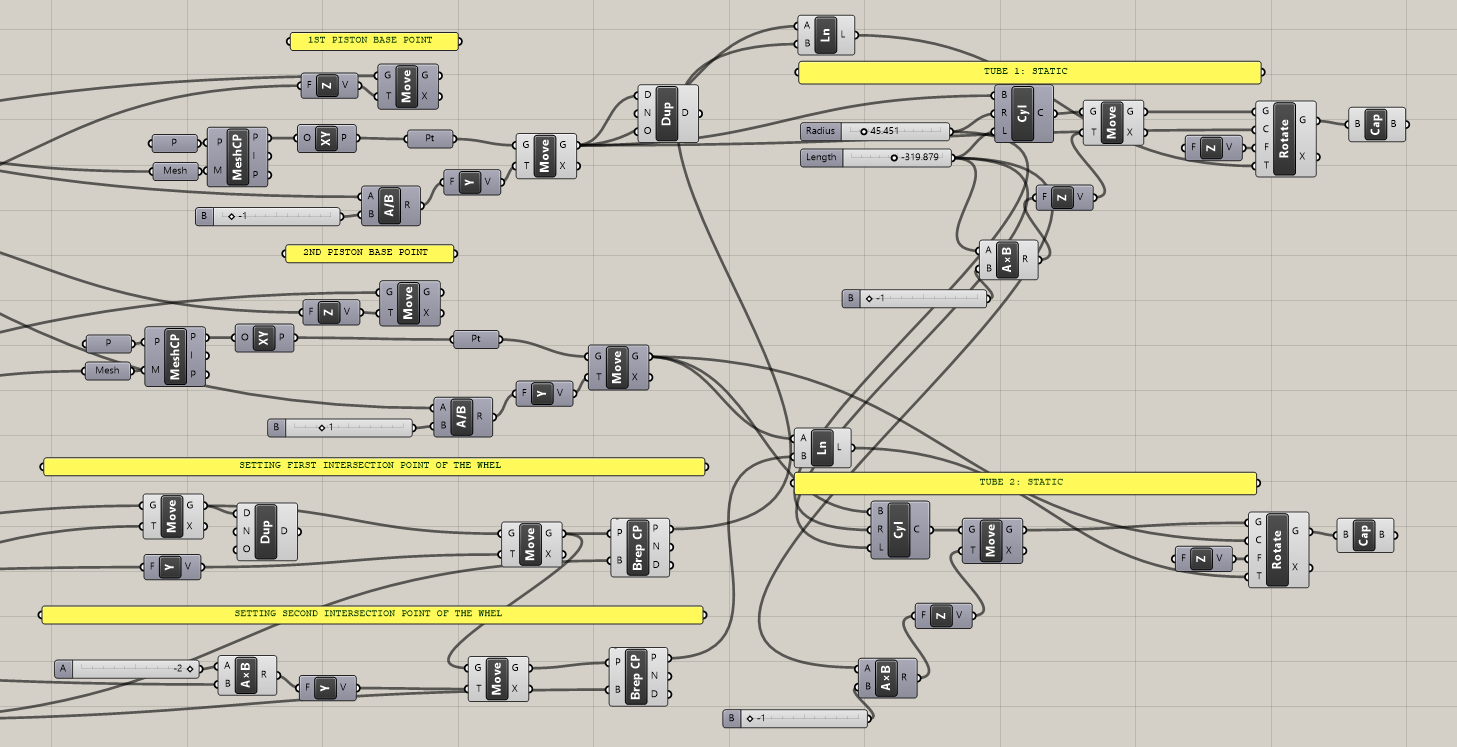
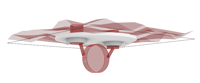
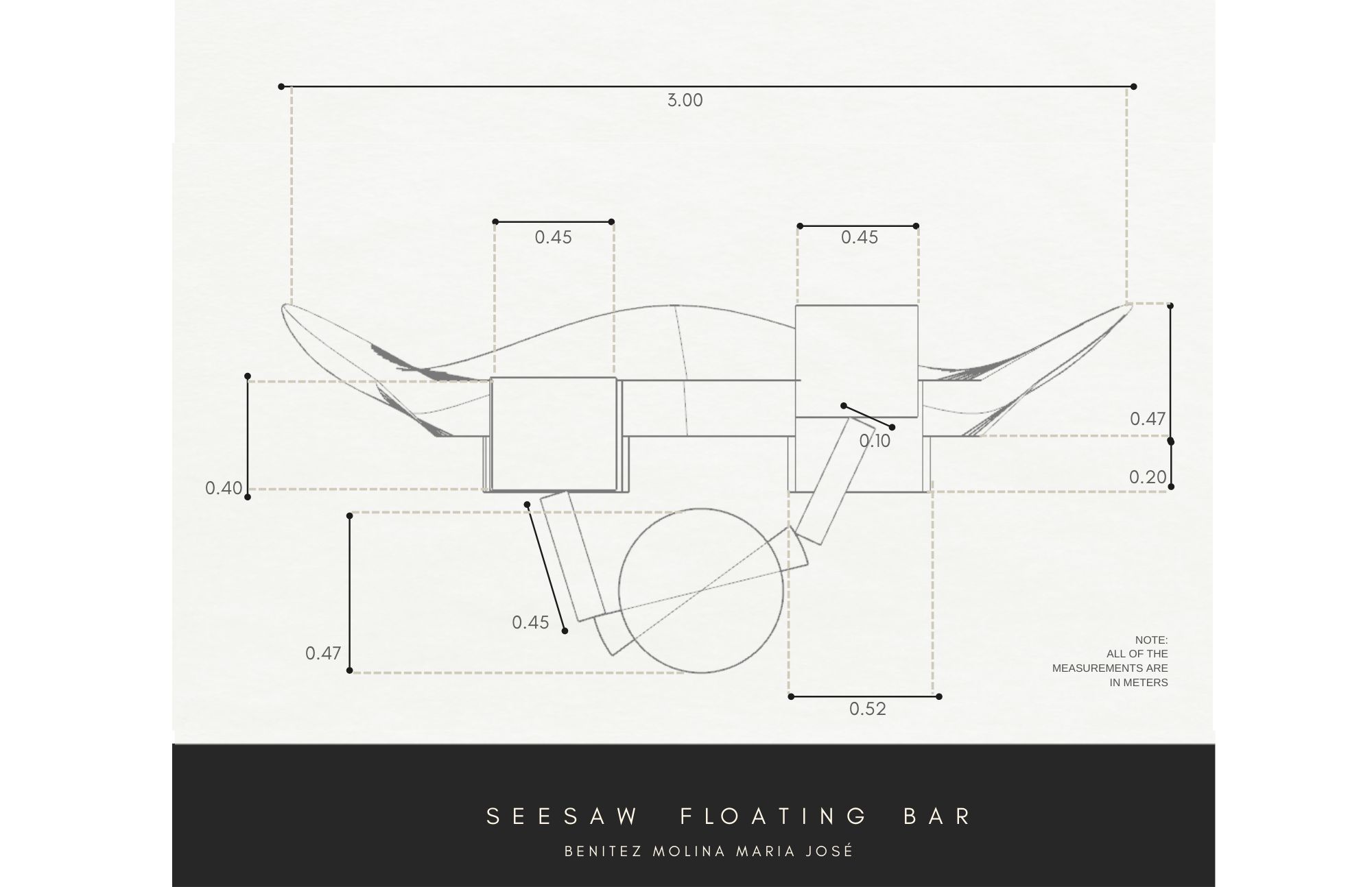
- The project is supposed to be a floating bar, which flotable seats work as pistons that are connected with a mechanical system underwater
DESIGN STEPS
PART 1
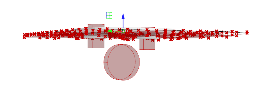
1.0 BASE PLANE: Waves and river level
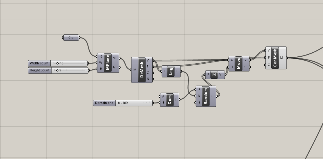
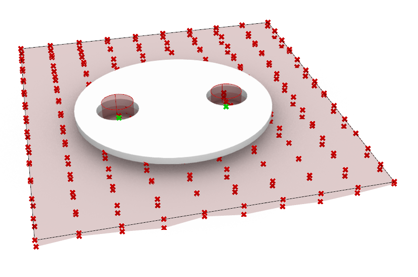
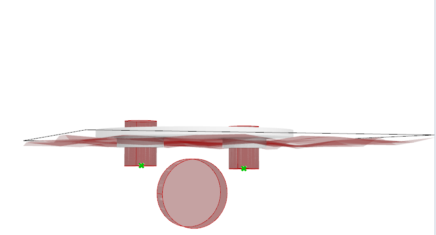
In order to simulate the waves and river level, will create a mesh that will interact with the mechanical system. This mesh will move vertically the pistons depending on the level of the water, making the system work.

In this case, the plattform of the project is already shown to contextualize .
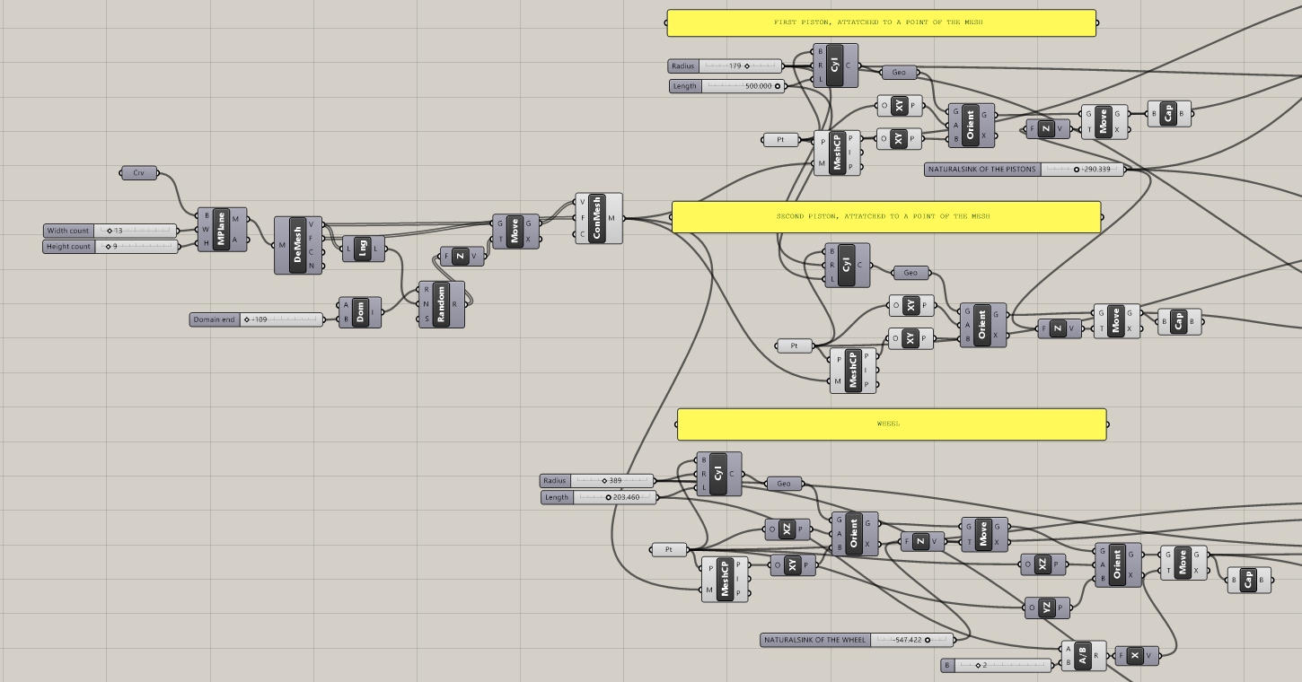
1.2 PISTONS
To attatch the pistons (seats) to the water and assure that their vertical movement depends on the waves, we must start modeling the cylinders in base on the closest points of the mesh. Also, we need to add some variables as the radius of the cylinders, the lenght and their natural sink on the water.

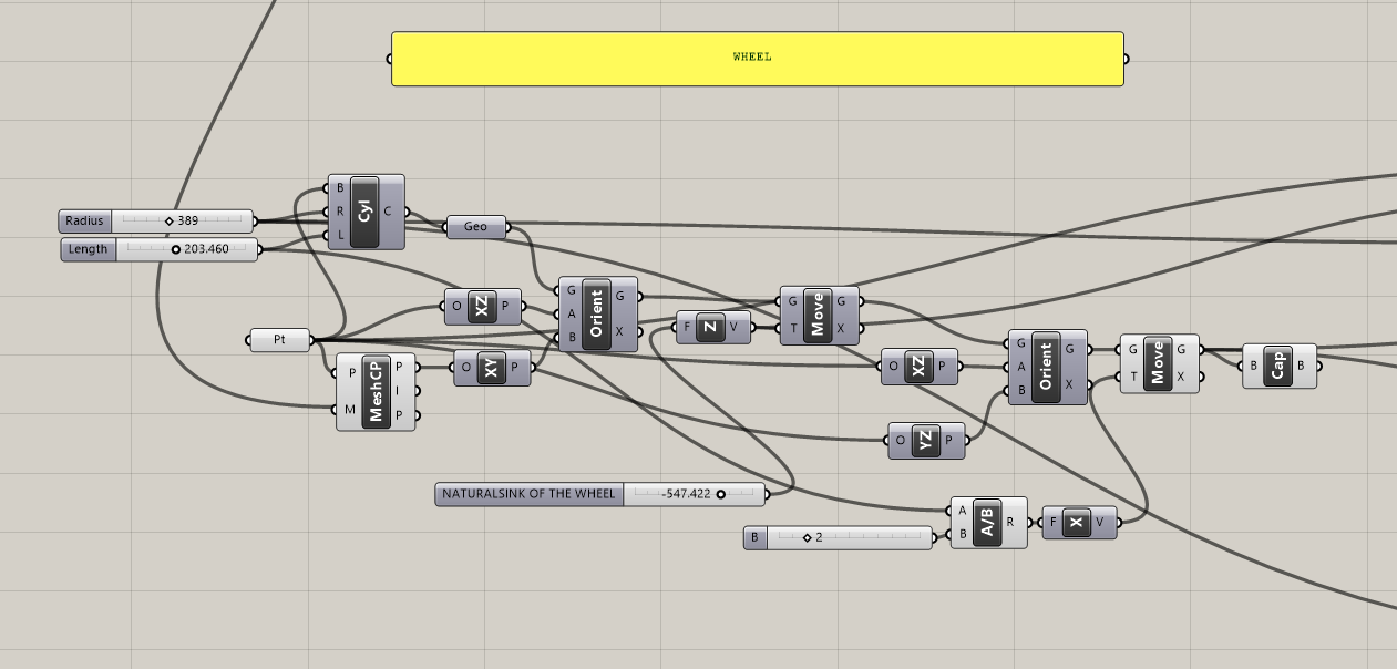
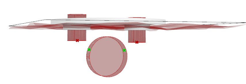
1.3 WHEEL
To code the wheel, we can also play with the variables but one of the most important aspects is the natural sink of the material. The wheel is supposed to be heavy in order to move the other elements.
2nd Part
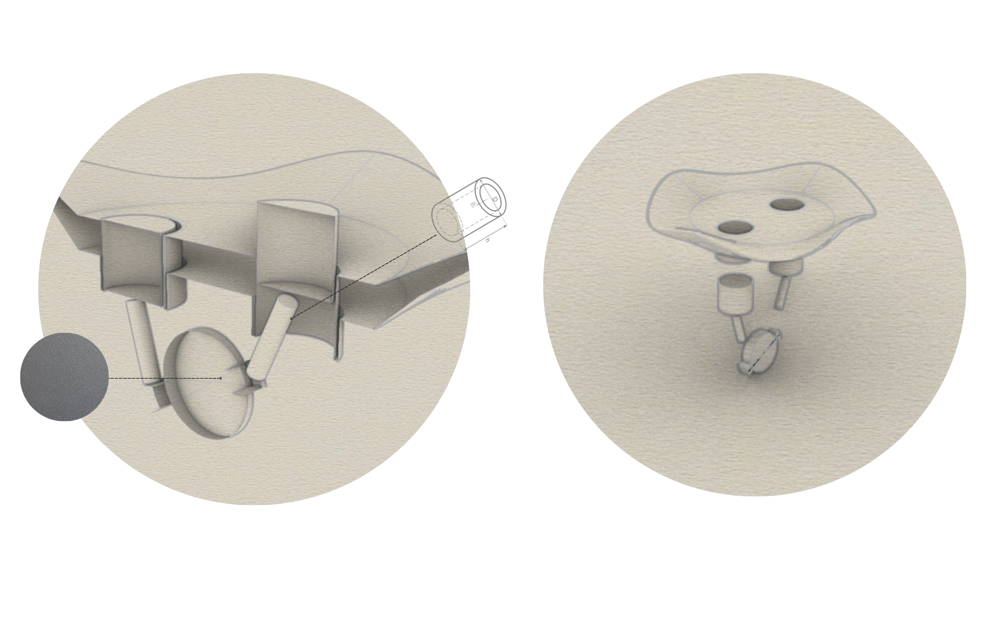
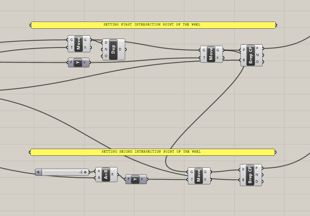
2.1 Piston´s base points
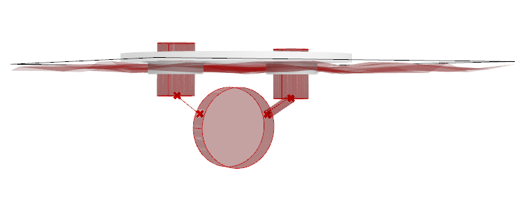
In order to model the tubes that connect the wheel with the pistons, we must stabilish a movable point on the base of the pistons, where the connection should be.
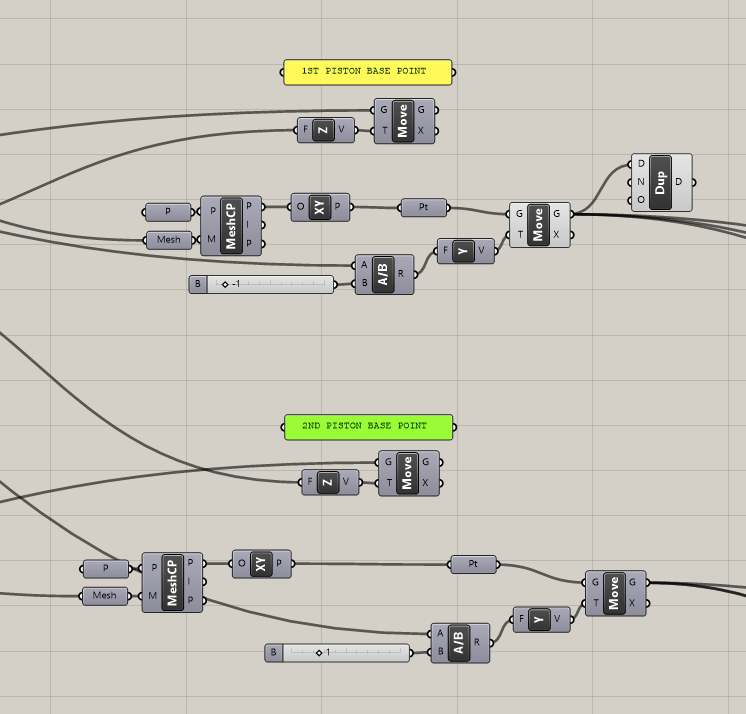
2.2 Intersection with the wheel
2.3 TUBES
After stablishing the variables of the cylinders, the tubes will separately work as the seats move vertically.

Finally, the sink difference will start working as a primary model of the mechanical simulation of the floating bar. This simulation can help us to imagine how a basic mechanical problem can be solved in grasshopper.