Introduction
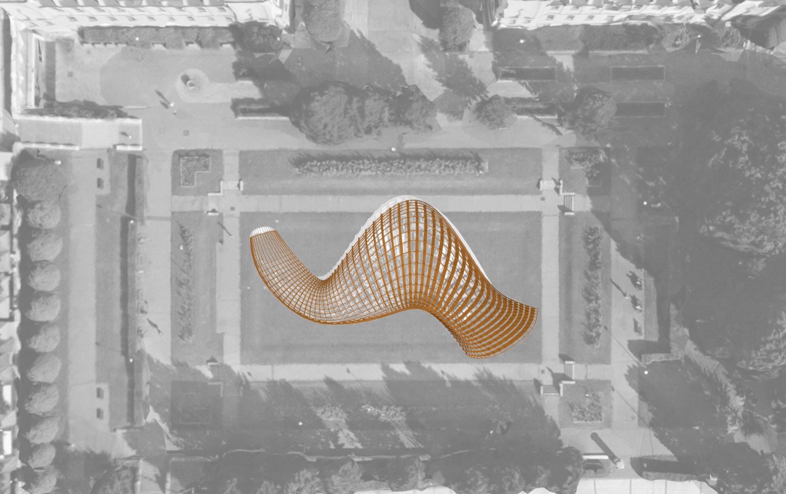
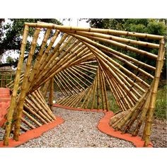
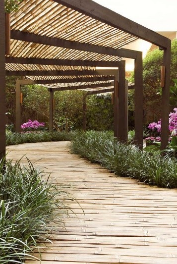
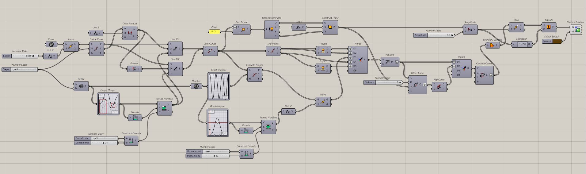
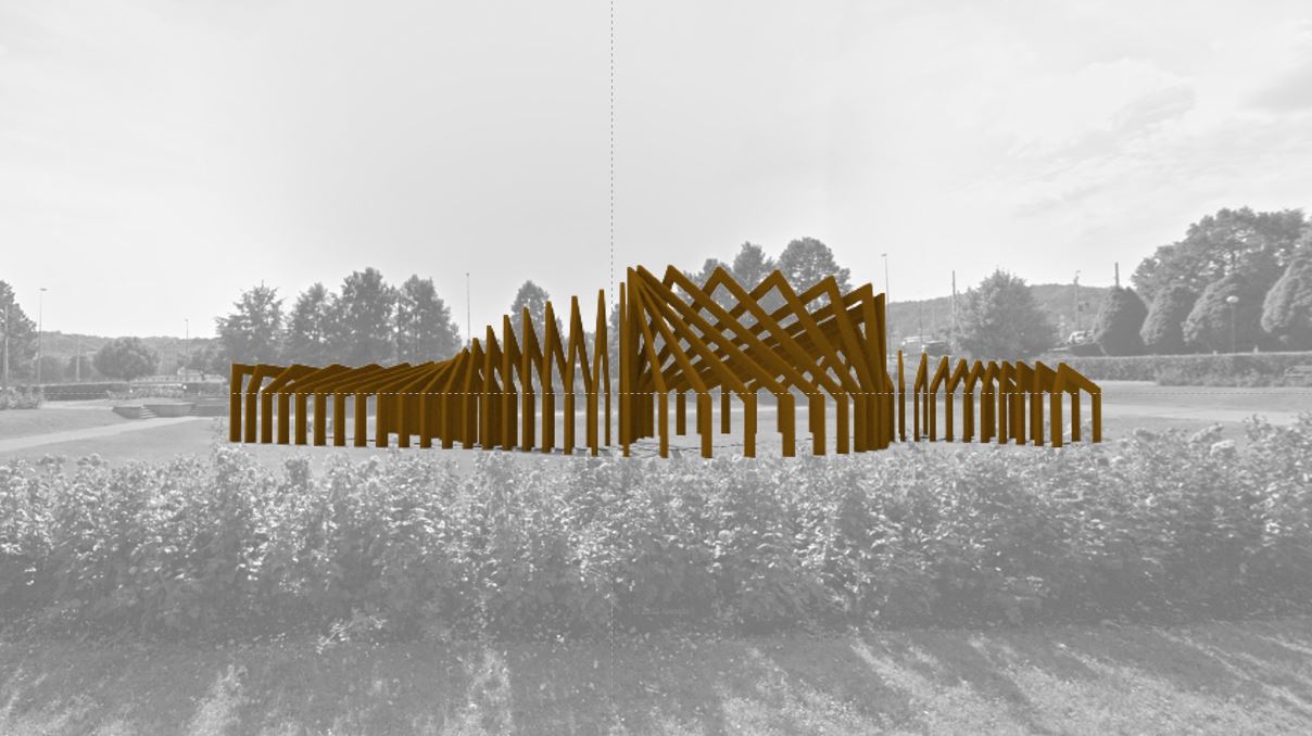
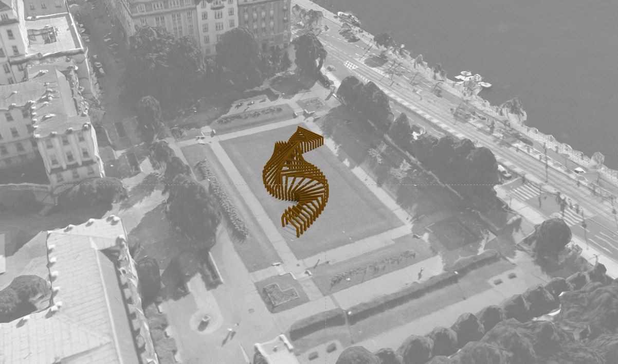
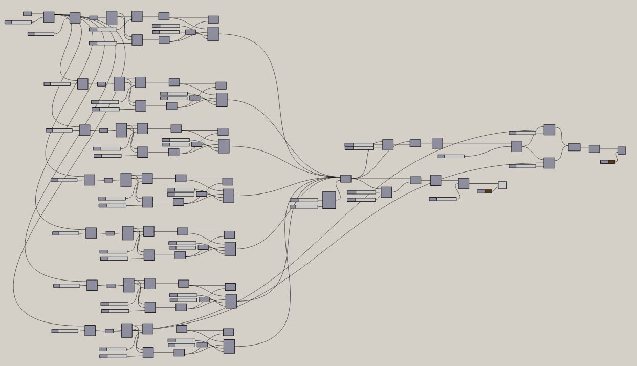
The main idea for this script is to model a wooden corridor using a curve and simple plug-ins, meaning, Range – Graph Mapper – Remap Numbers – Construct Domain – Merge, creating this geometrical wave within the structure. The built model was designed to be integrated into the green square, Zítkovy Sady in Prague.

Concept
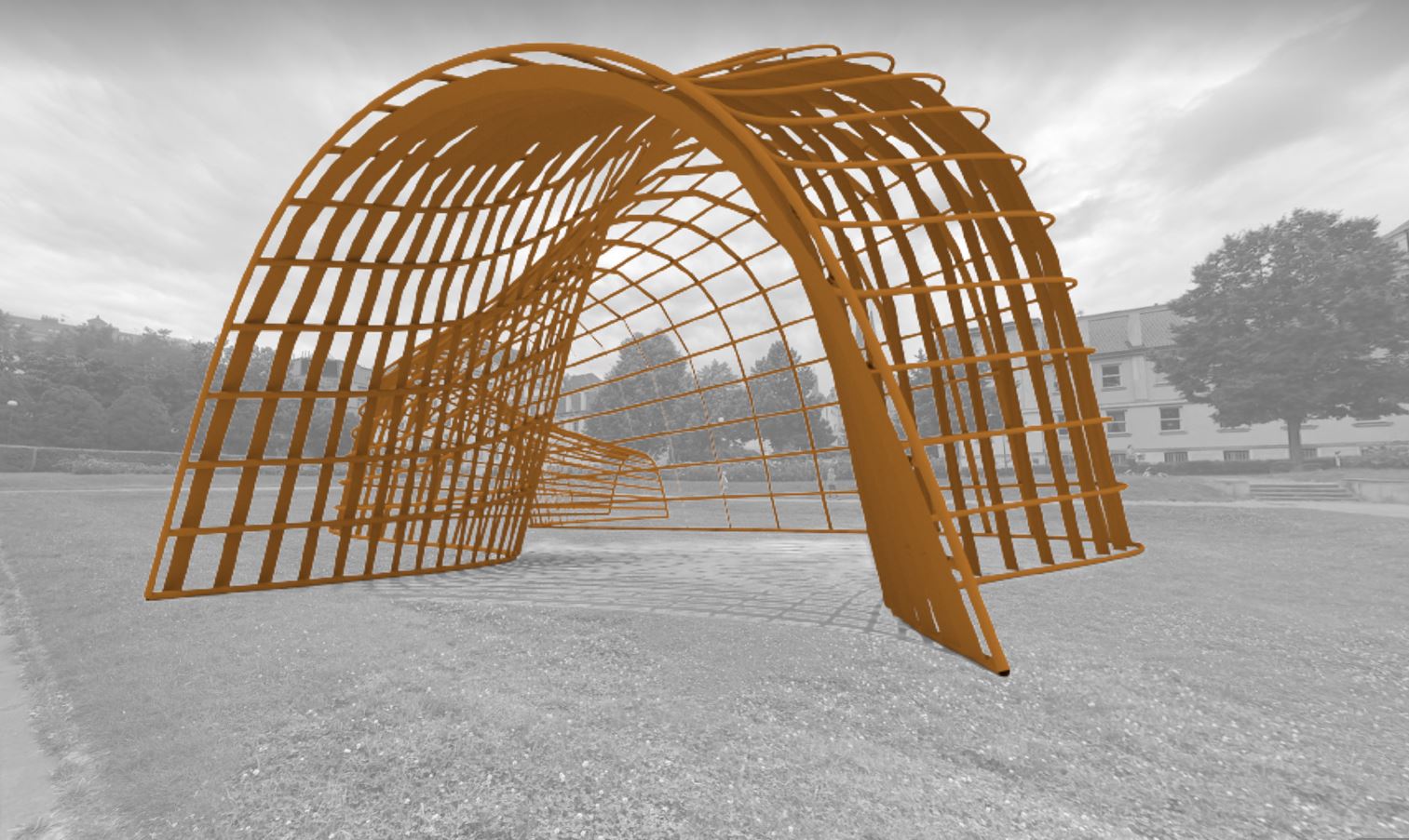
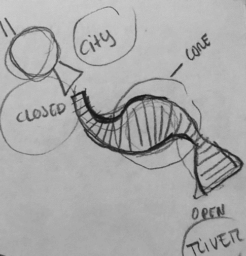
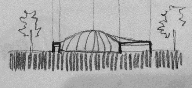
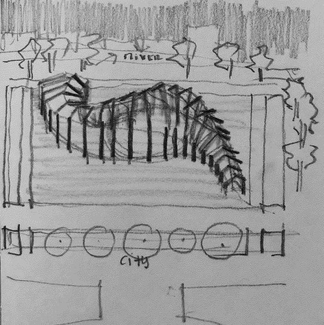
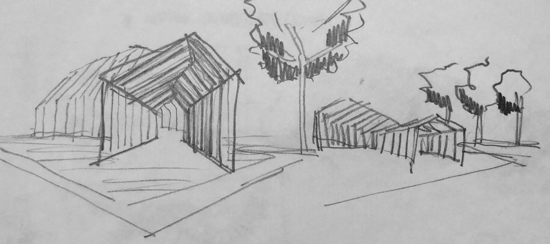
The concept, was to create a public corridor that would provide dynamic and movement to the empty square. Taking into to account the existing place, some aspects were important to design for understanding the pretended shape. First, at the top is designed a small entrance facing the city, capturing people’s attention and their desire to get closer and enter the space. In the core of the structure, we see the larger and more invited space where everyone can meet and contemplate the different atmosphere within the city. And finally, in the lower zone the big entrance, facing the river. From this perspective we exit the wooden corridor, seeing an open and interesting view to the Vltava River.
Full script using Graph Mapper through a Curve
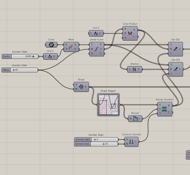
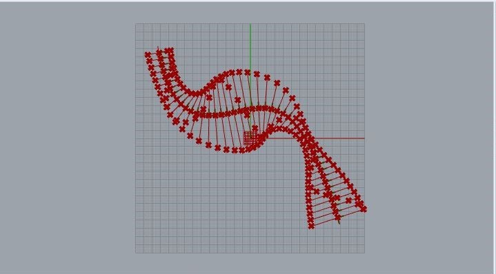
1 Part | Designing the Curve
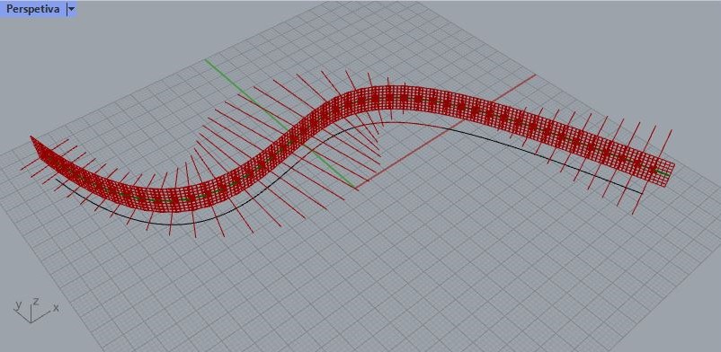
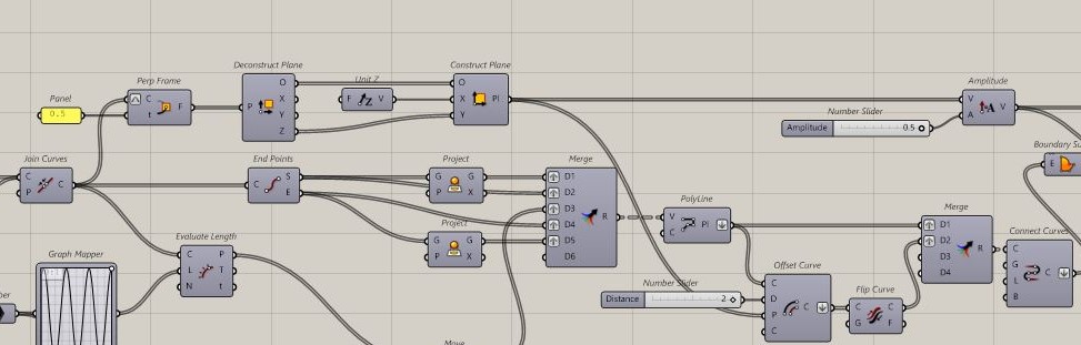
To create this corridor shape, first you need to design a curve, joining the drawn line to the curve input. Then to settle the curved line, we use Move and naturaly associate it to the Unit Z plane. The next step is very important to define how many “structures” or archs you want. So using the Divide Curve you can regulate it’s number through the Number Slider. To define each arch along the curve, we need to use the process of unifying the vector Cross Product, with the two Line SDL and one more Unit Z plane, to stabilize the structure. Also, don’t forget to add the Reverse do create different directions. Then, to control it’s shape and dynamic composition you add Range with it’s Number Slider, previously connected to the Divide Curve, and joining the Grapf Mapper with Bounds, Remap Numbers (don’t forget to link this one with the two Line SDL inputs) and finally the Construct Domain ( defining where it starts the organic parts and where it ends). Now you are able to model, in your own way, the organic composition for the public corridor.
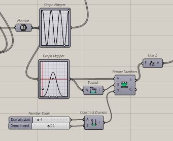
2 Part | Creating an organic shape
For this second part you need to repeat a bit the last process, but for now the idea is to define the height of the wave that is designing the highest point of the curve on each arch. To model as you wish you can use in the Graph Mapper the Graph Editor and change the wave. The first Graph Mapper controls the design of the horizontal directions of the wave and the second one, controls the height of it. Regarding, the Construct Domain is ensuring where it starts and ends the height in the middle, as well as where it starts and ends in the exterior points, like an organic body.
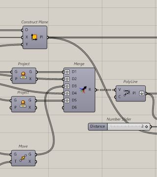
3 Part |Designing the structure
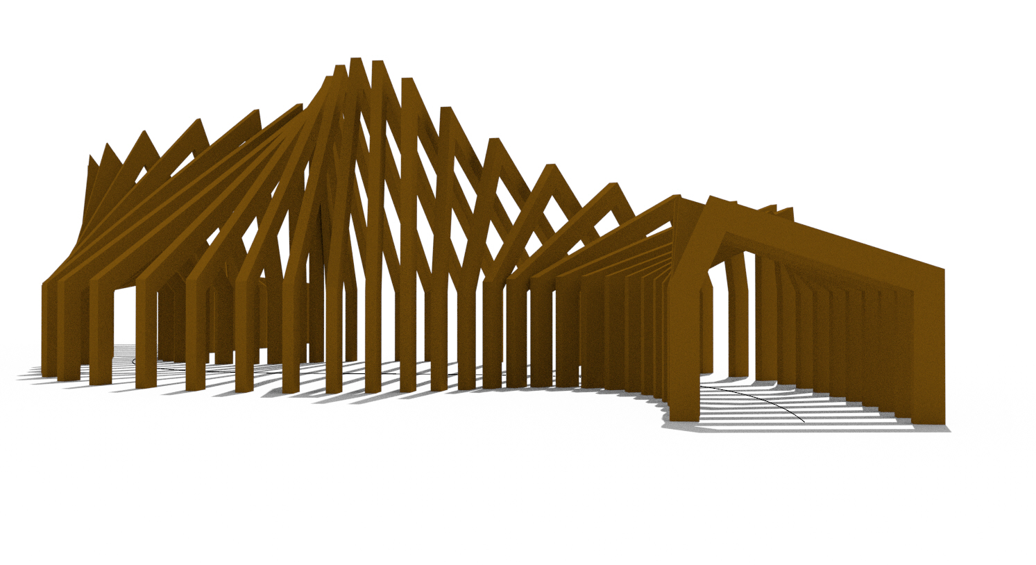
To delimit and define the vertices of each arch structure, as if it were a modeled roof that rests in two walls with different heights (triliptic system), we use End Points associated with three Project inputs unifying them with Merge. To model this process we need to bring together Merge with this new one, Polyline. From this part of the tutorial, we can understand more of it’s volume and composition. Don’t forget to clik on “Flutten” whithin the PolyLine.
4 Part | Creating planes
For this next step, we need to duplicate our structure to model and create volume approaching reality. To construct this part you need to add Prep Frame, joining it with the existing Join Curves, with this move we are designing a new plane whithin the curve. Consequently we link this last one with Deconstruct Plane and then Construct Plane associated with a Unit Z Plane. Now that we have all the inputs, we only have to join this process with Offset Curve, knowing that this one is linked with the previous PollyLine created whiel we were merging the lines of the structure. Throught the Offset Curve, we can regulate the size and it’s shape. Finally, we use Merge to link again the last process and we finish with Connect Curves (Flatten) to create a transparent plane for each arch and not just a line.
5 Part | Three – dimensional model
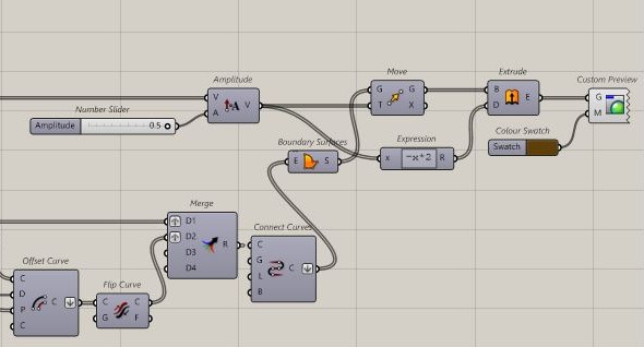
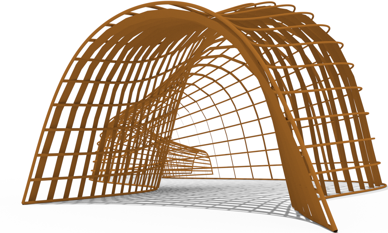
Now we need to create a surface, and for that we use Boundary Surfaces previously linked with Connect Curve. This composition needs to be duplicated again, because we want to see volume and it’s 3D side. For this matter we add, Move and Amplitude (that we can regulate and has to be connected with Construt Plane). The most important input is Extrude, because when we add this one, our model becomes three-dimensional and we can imagine the built space. The last step is to choose what the colour that we want for our project. Using Custom Preview and Colour Swatch we can choose it.
6 Part | Renders
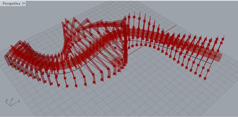
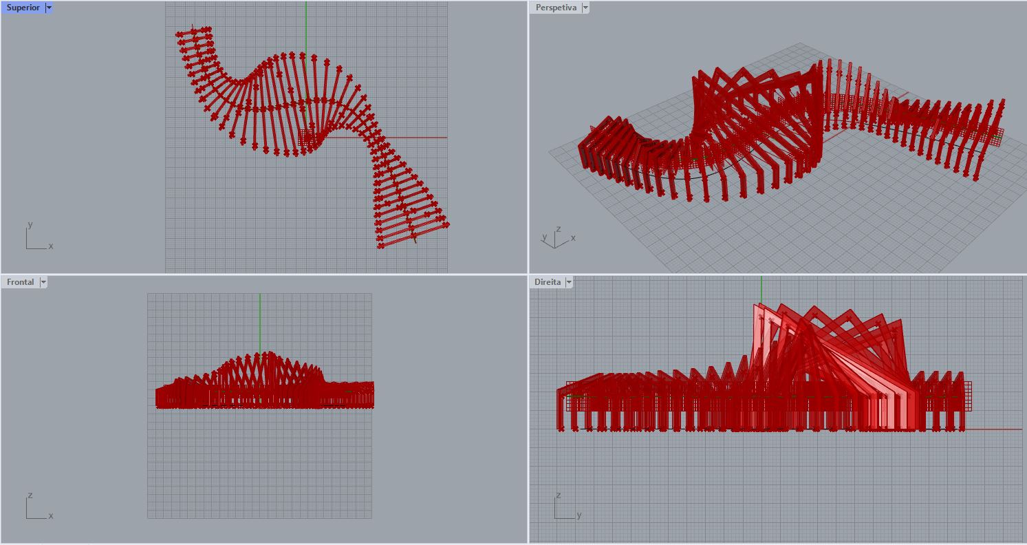
To present our final Project, we need to do some renders in order to get as close as possible to our final goral. We can start by saving the file from Rhino as PNG, choosing the transparent background option. It’s much easier than it is to erase each white part from the image. In my case, I chose the some persppectives that help us understand the composition and how it is arranged in the site.

Catenary Process | Another process as example for this tutorial

Full script using Catenary Curve
Part 1 | Design the curve and it’s 6 arms
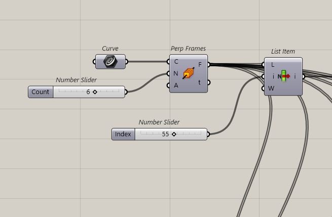
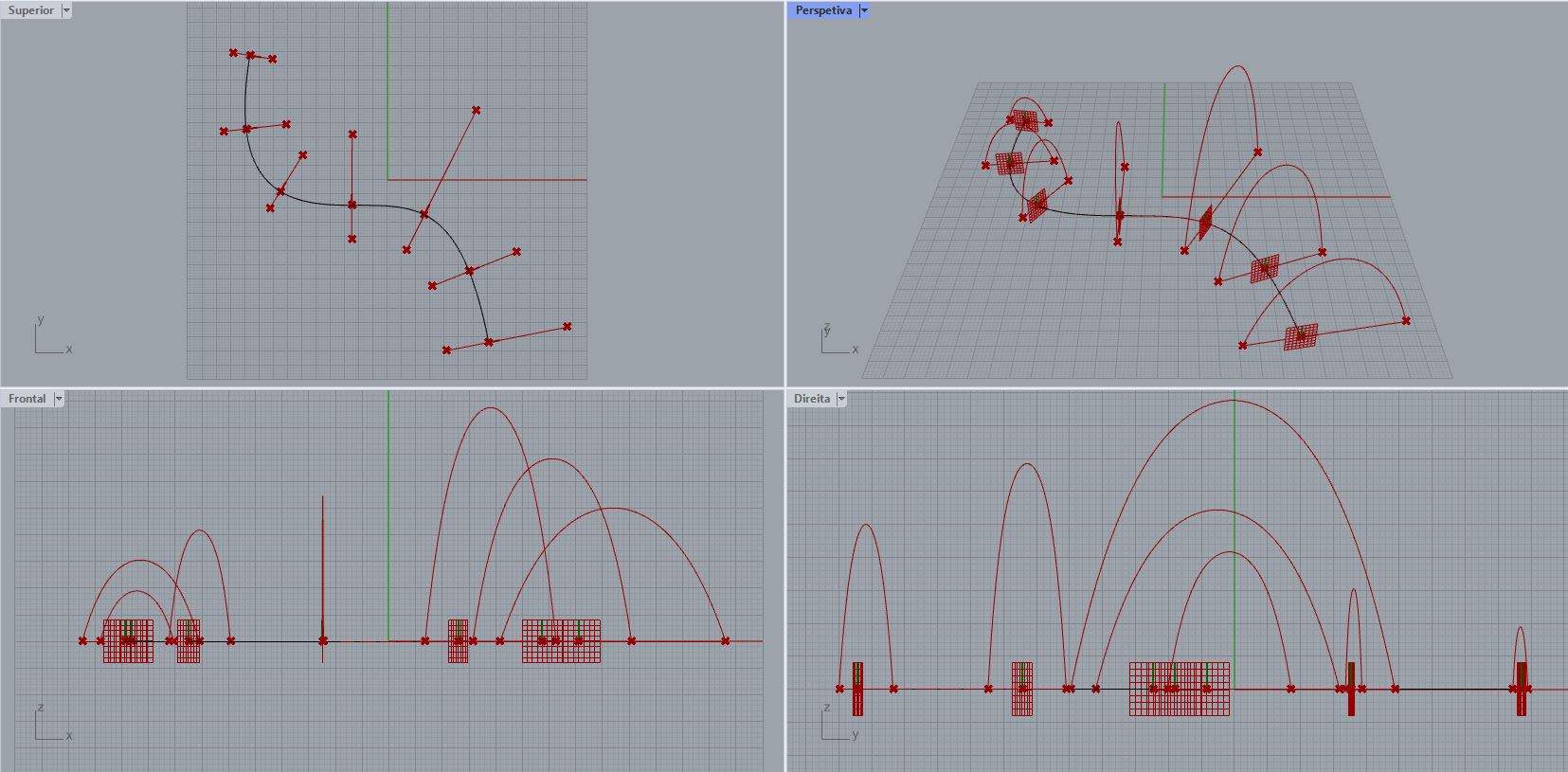
Part 2 | Catenary

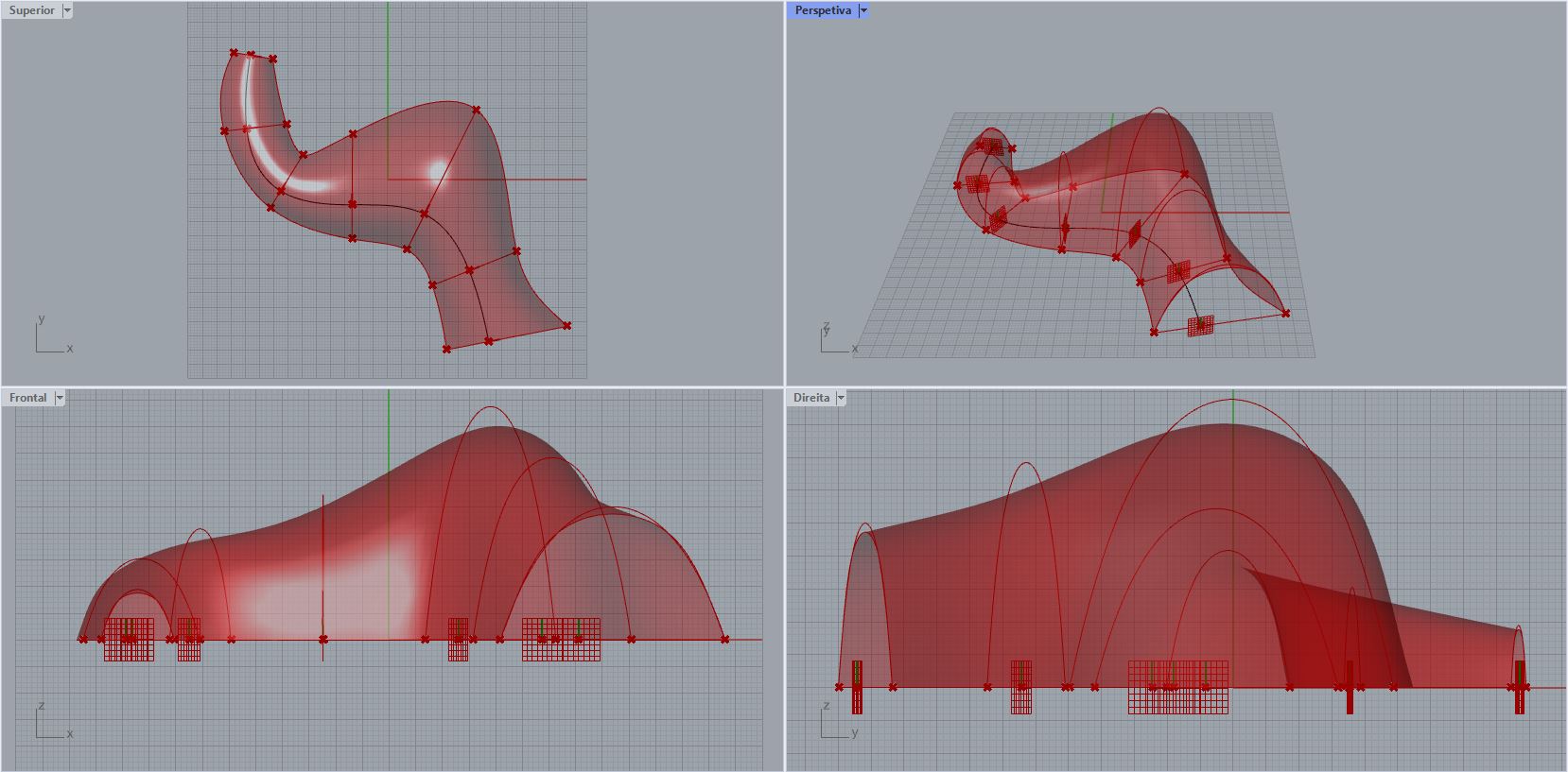
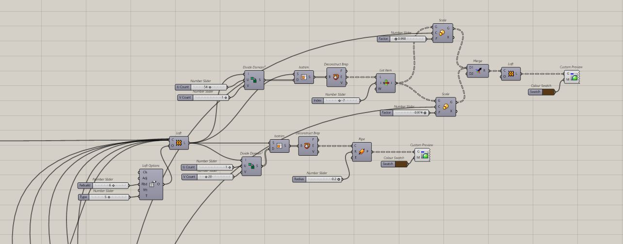
Part 3 | Modeling
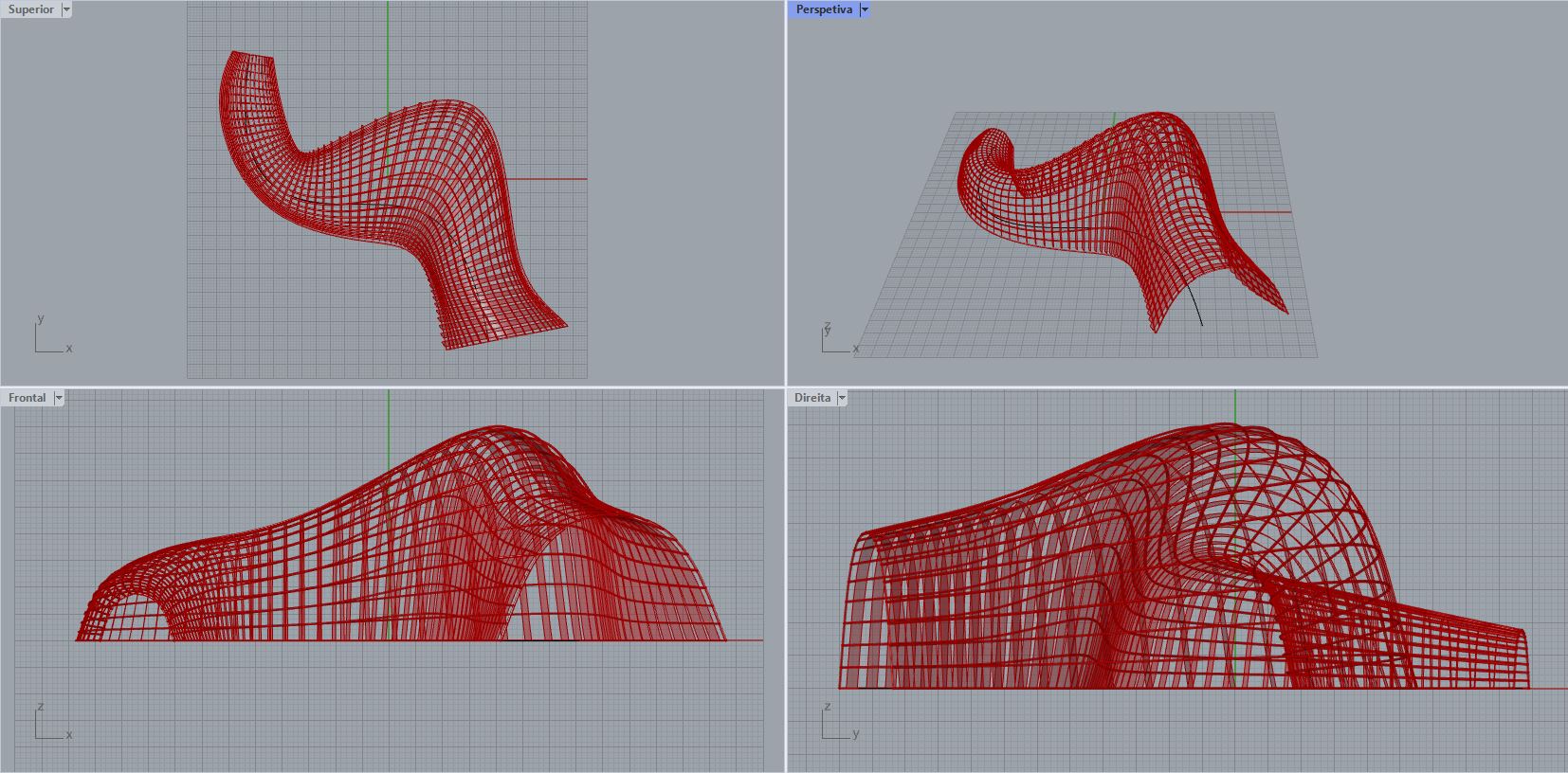
Some images