FIRST STEP : CONNECTORS SETTING
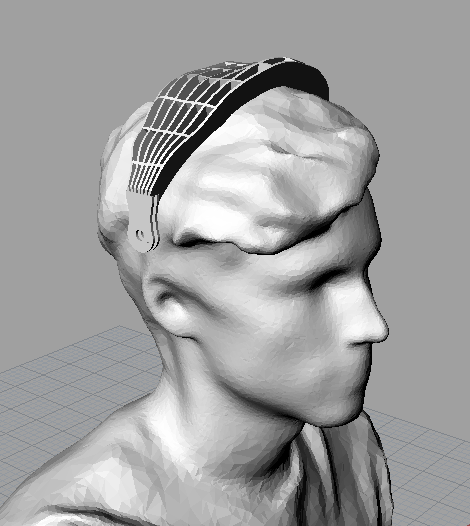
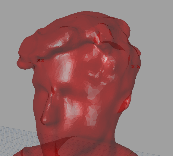
I 3d scan my head in Delnicka’s makerslab as a basis of design.
Then I selected on this mesh the two closest points to ears
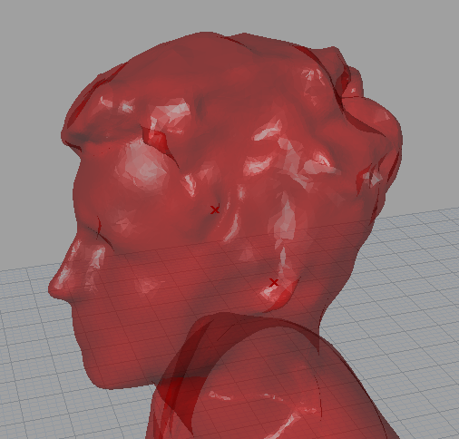
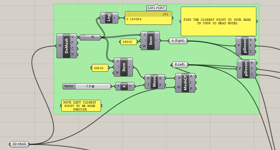
Then I moved those two points in a definied z and x direction from ears to have the connector’s point.
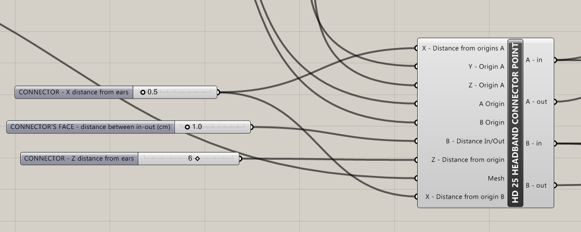
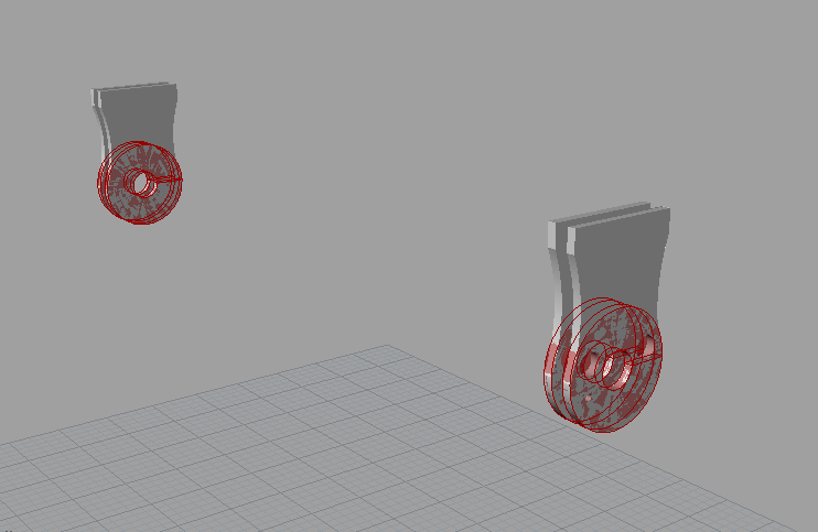
Then I set the connector position with 4 cylinders ( connectors are composed of 4 parts).
I draw the connector models on rhino and I moved them on the circlec

STEP 2 : HEAD BAND MODEL
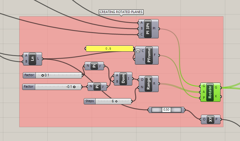
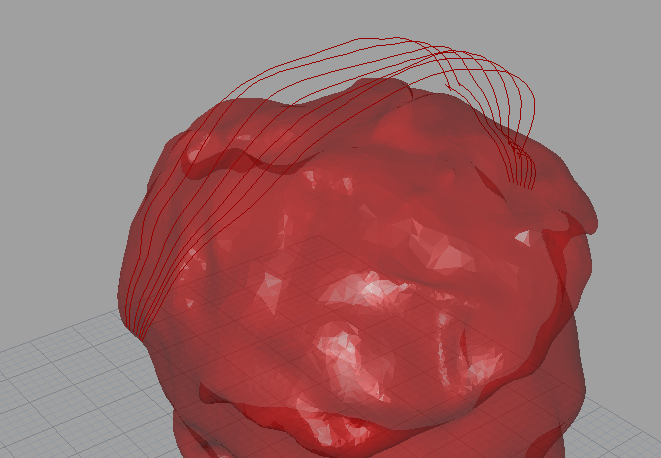
Headcurves : I rotated 7 planes and found the intersection between those planes and the Head mesh
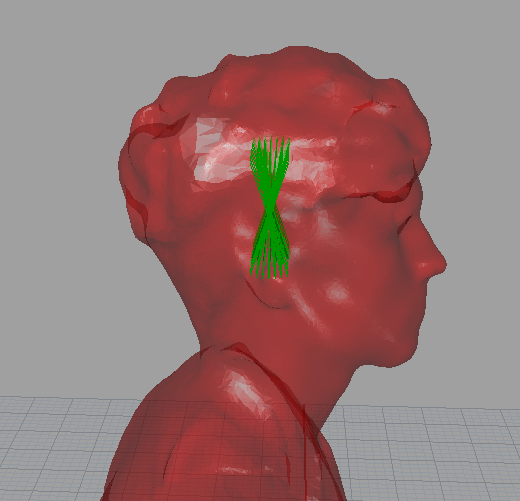
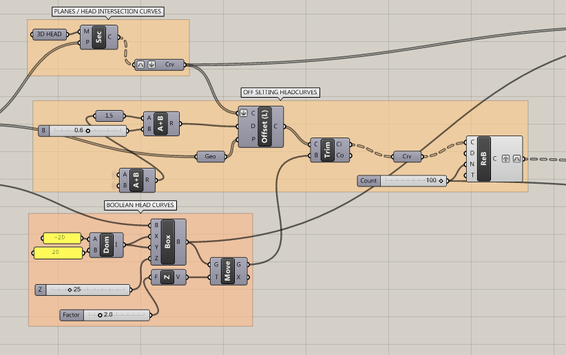
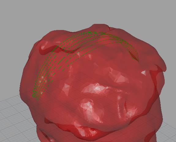
Then I offset and cut those curves
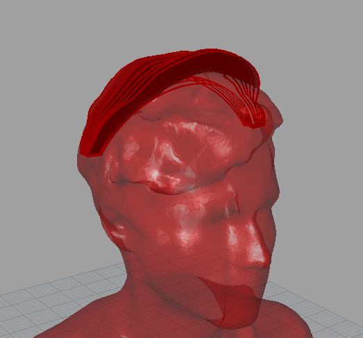
ARC CURVES : For the bottom part of the head band I used arc curves that i rotated in the same way than the head curves.
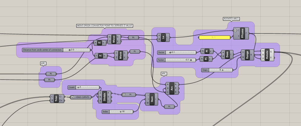
Then I created ruled surfaces between those 2 differents curves, in order to have the headband surfaces.
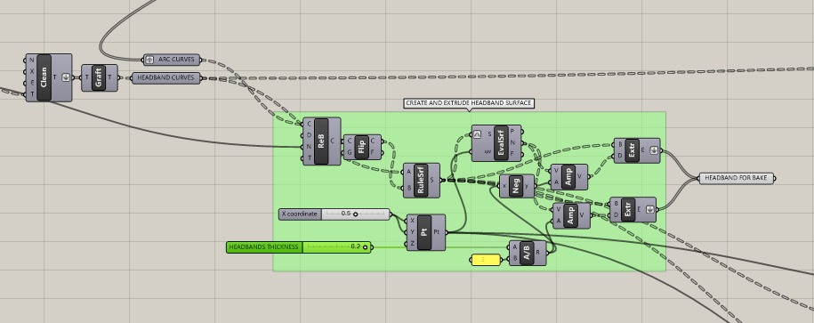
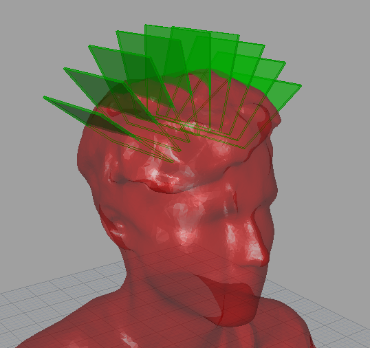
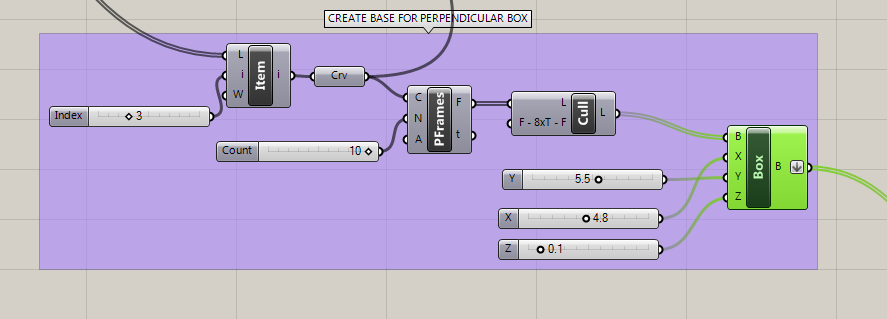
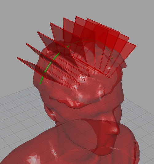
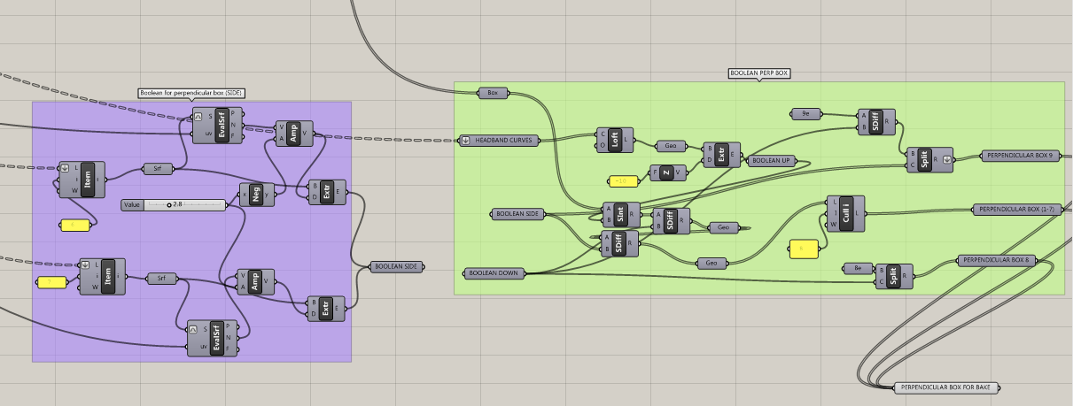
STEP 3 : PERPENDICULAR BOX
I created 9 perpendicular box that i will cut later
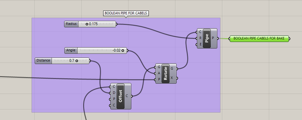
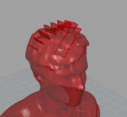
Then I draw the boolean pipe for the cabel in those box
Boolean operation : I made the first boolean operation of those boxes on Grasshopper
STEP 4 : FINISHING IN RHINO
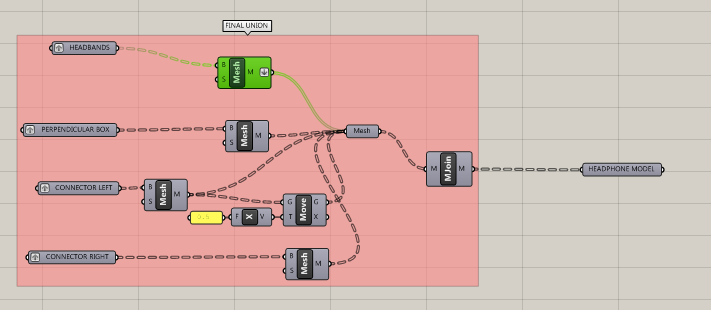
I bake the headbands and the perpendicular boxes on Rhino and i did the finishing of those pieces in Rhino. Finally I re-import the finish pieces on grasshopper and convert them into mesh and join them in one mesh in order to send this model to 3D Printing.