
Goal:
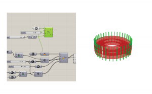
Use domains, sweep, and array to create a helix structure with an editable structure. This tutorial uses only Grasshopper components and does not require any plug-ins.
Files:
Steps:
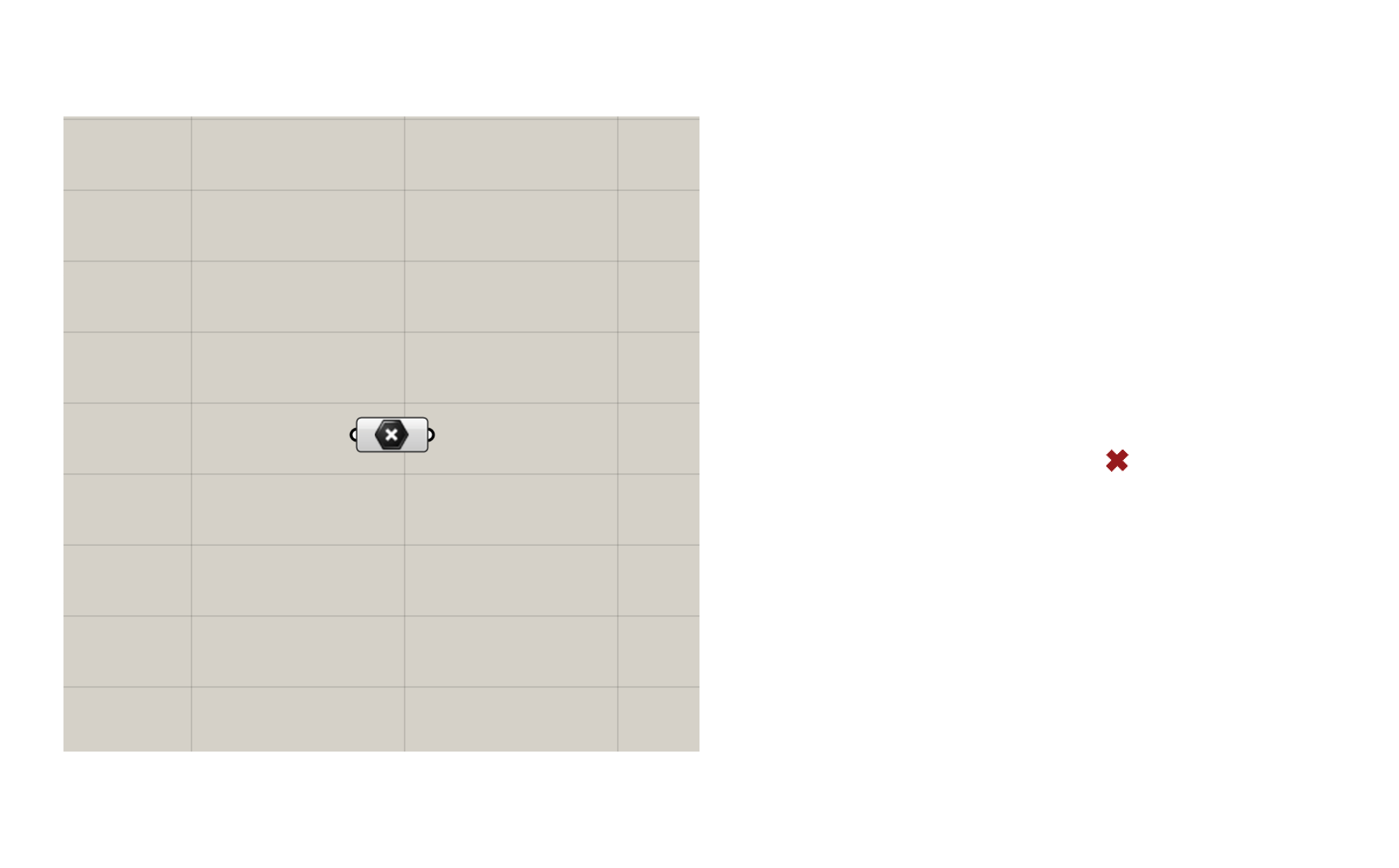
Use the point component to set one point for the center of your helix.
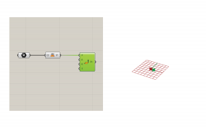
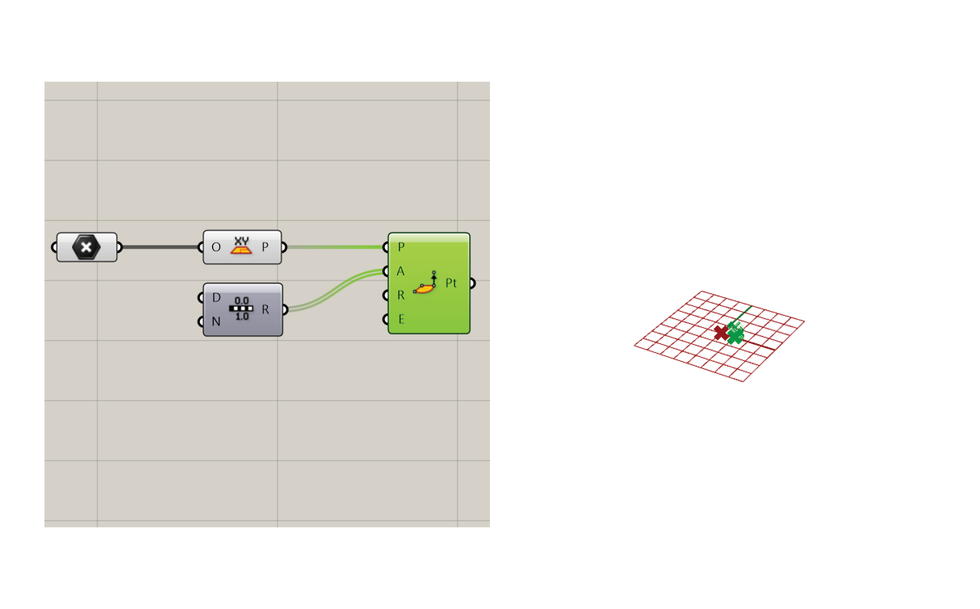
Connect the point to an XY plane to anchor the structure to the ground plane.

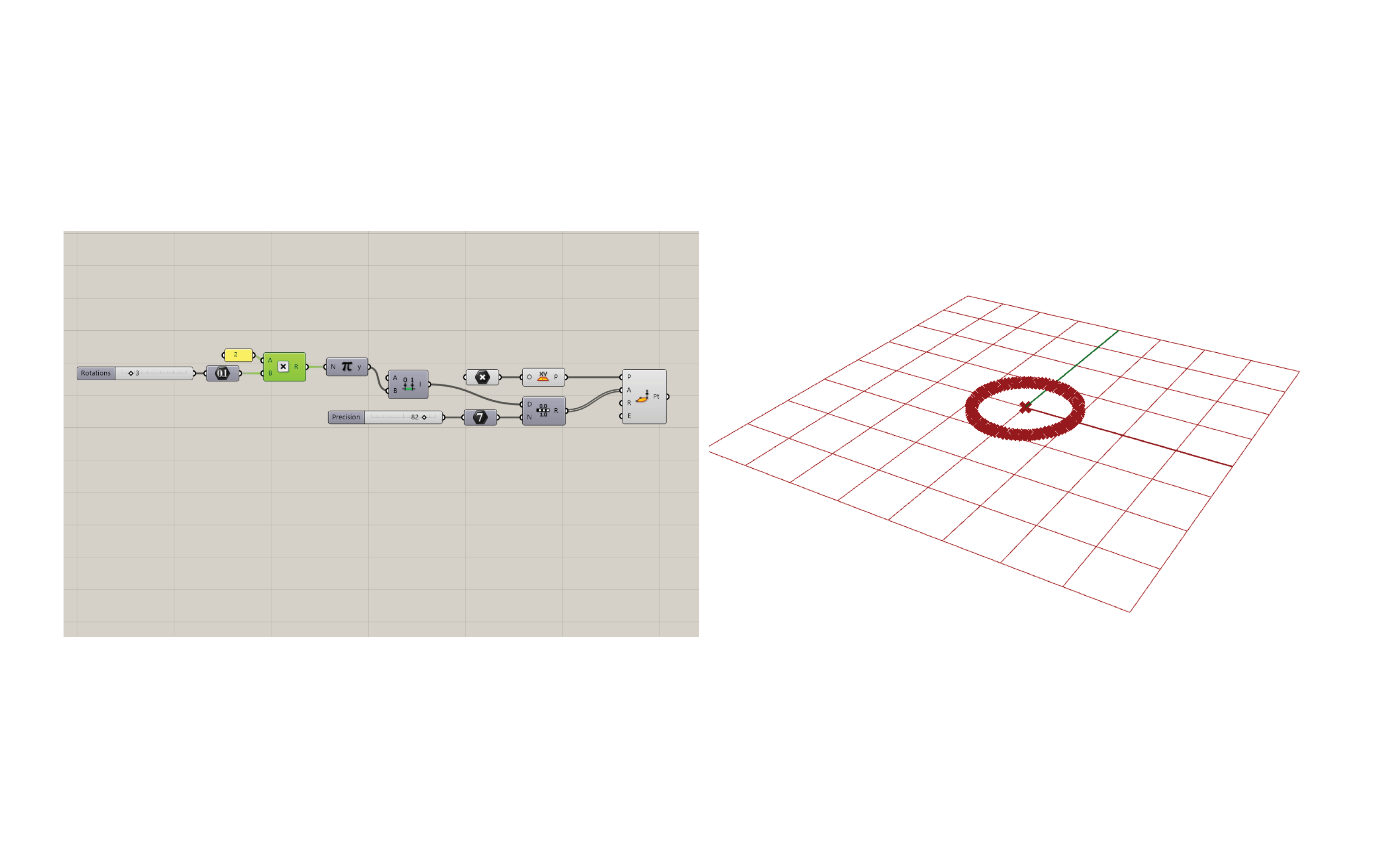
Place the Point Cylindrical component. This will create a set of points for the helix curves to interpolate through. This slider requires several elements to make it work.
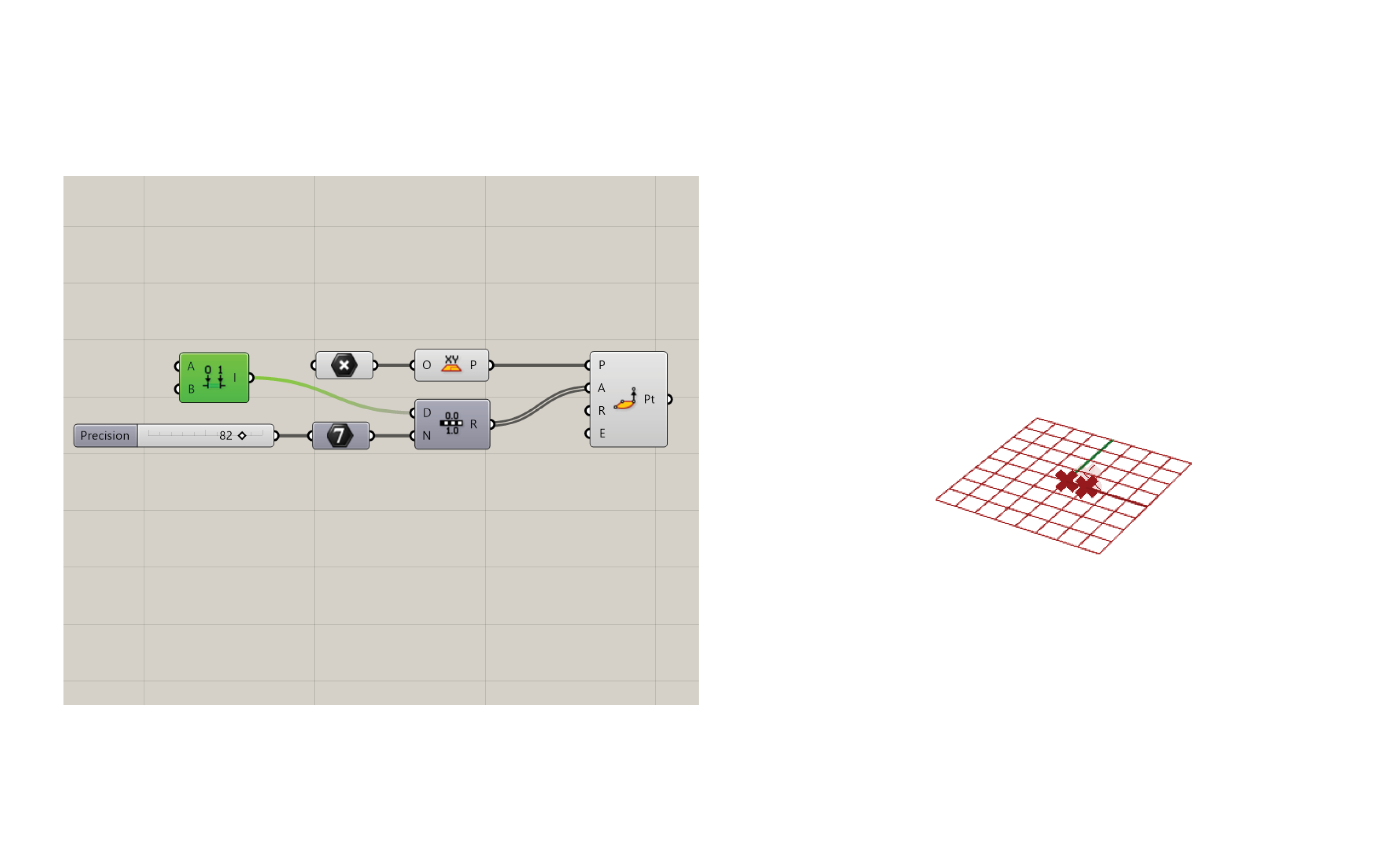
First, you need an angle. This input will be a range of numbers because the amount the curve will rotate between points will vary.
The range needs a domain and a number. Create an integer component attached to a number slider. The number slider is called precision, because this will dictate the amount of numbers in this range. We cannot have half points, so therefore integer is used. This integer translates to the number of points that will make the curve.

Also add a construct domain component to create the domain for the radius.
Create a number component attached to a slider called rotations. This will define how many times the curve will rotate around the center point. The rotations slider should begin above zero, or else it will break. Feed this number into a multiplication component with a panel that says 2 in the other input. Type //2 in the command line to use a panel instead of a number slider. The number of rotations will be expressed as a factor of pi, because it is a cylindrical shape. Attach to pi and then attach to the domain end.
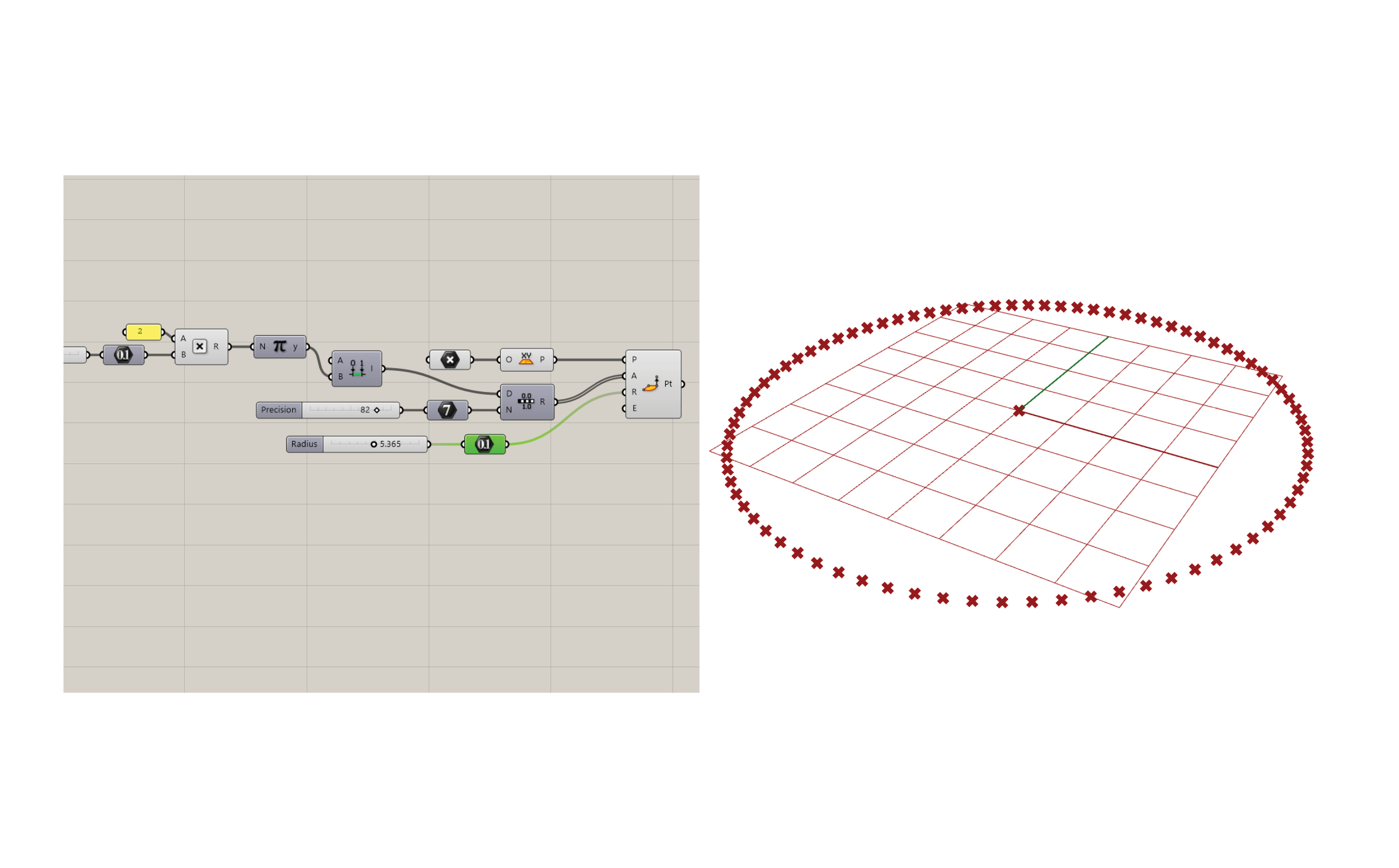
Now we need a radius. Create a number and attach a slider called radius.
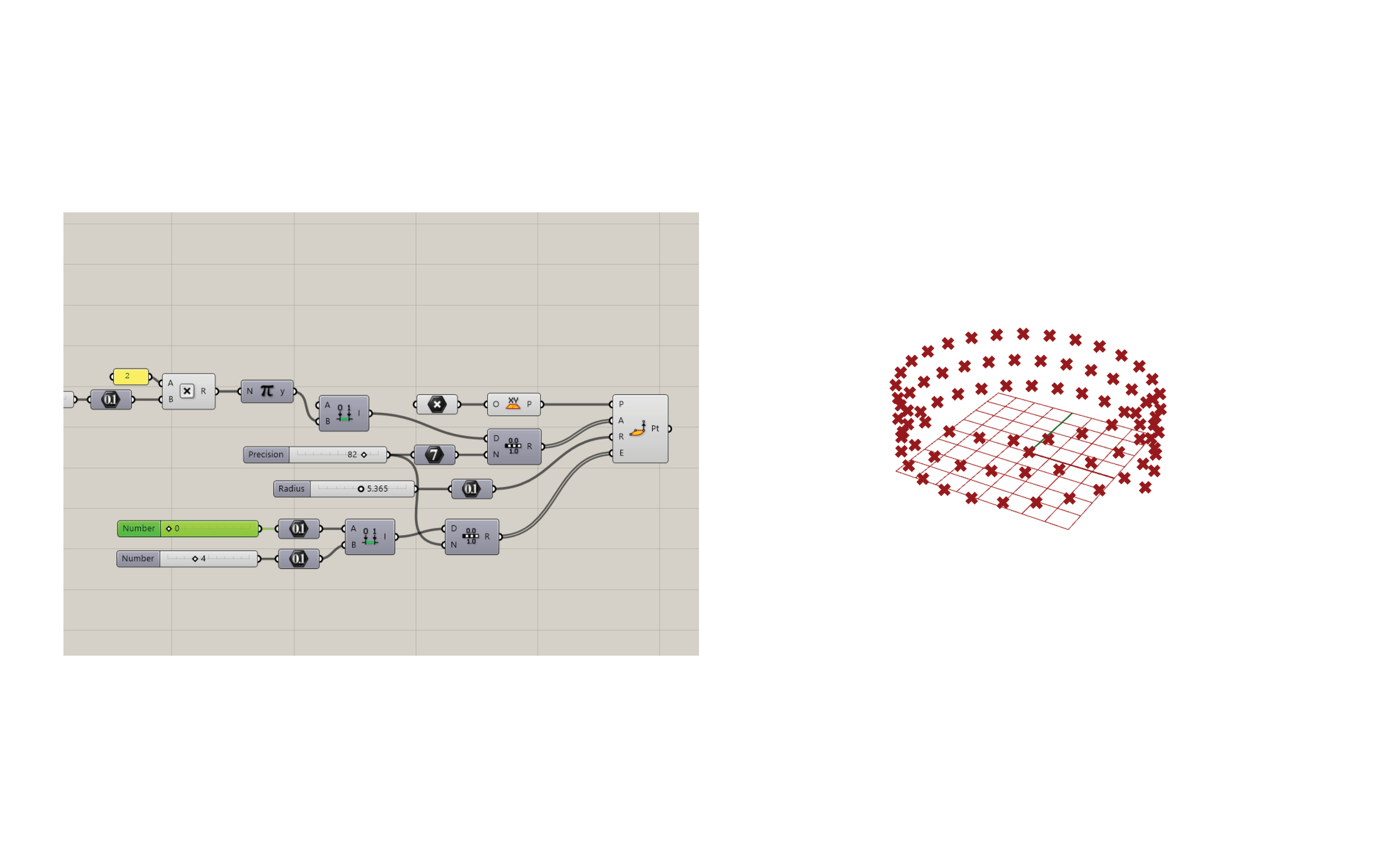
The elevation will be determined by a range component because we want to distribute a number of points evenly between the minimum and maximum heights. The number of the range will connect back to the precision integer, while the domain will be composed of minimum and maximum numbers. Create these numbers and connect them to their relative sliders.
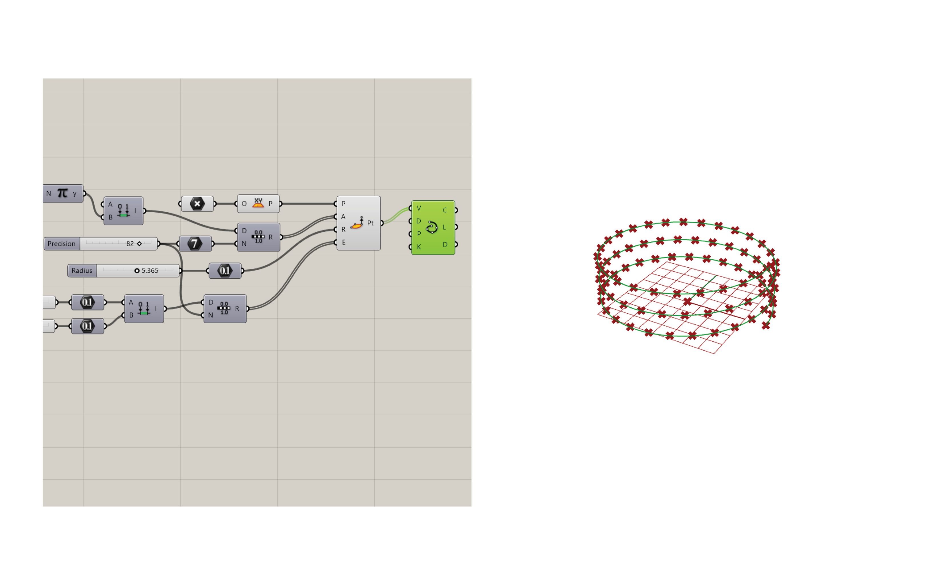
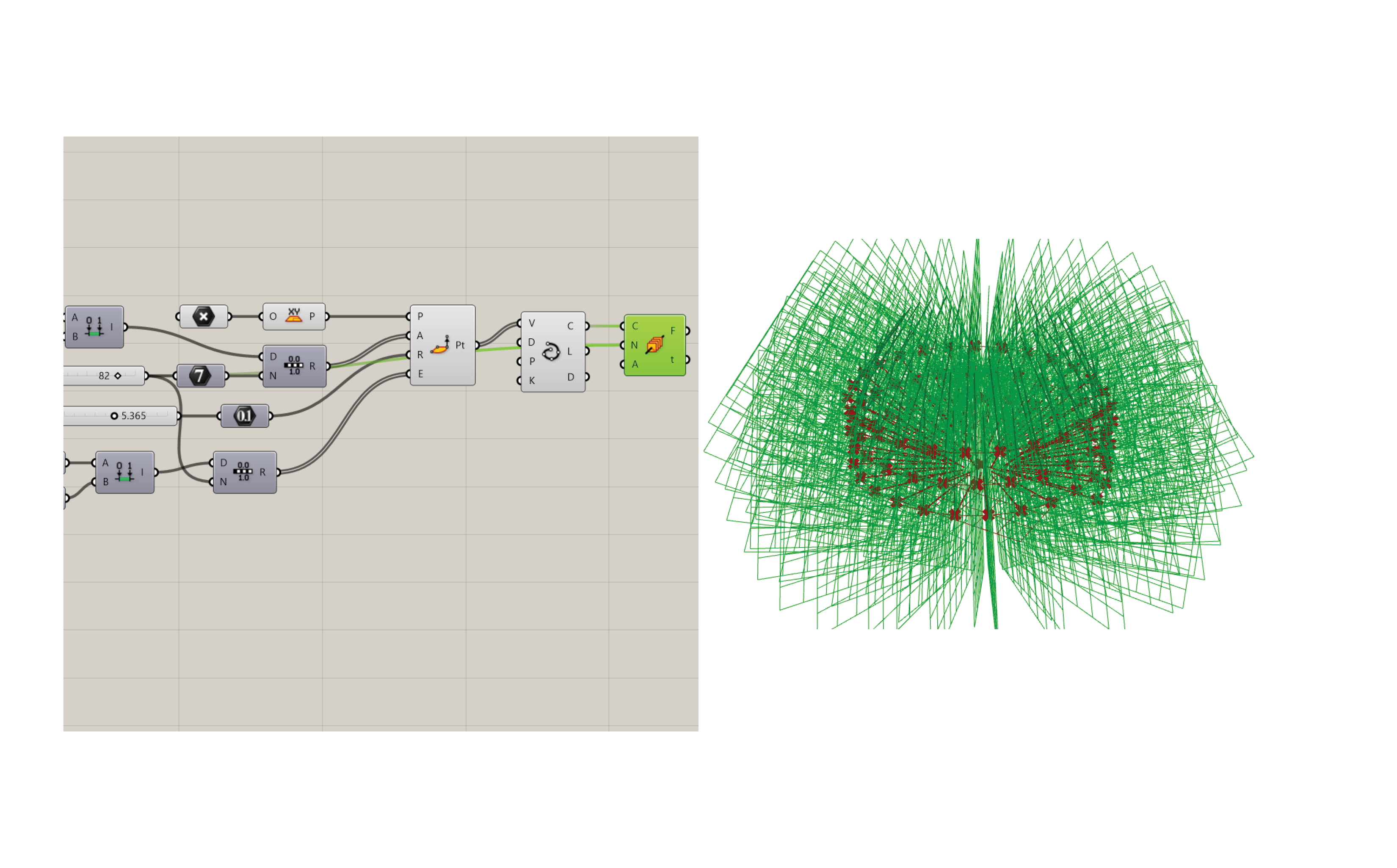
Now you should have a helix of points. To make this a curve, we will used interpolate curve. Connect the points to the vertices input.
Now that you have a curve, you need to sweep the profile of your surface along it. However, interpolated curves are not suitable for this. You must orient the curve at each point using Perp Frames. Link the curve output of interpolate into the curve input of Perp Frames. For the number of frames, link it back to the precision number at the beginning. Now you will see a frame at every point.
These frames may not necessarily be perpendicular to the curve angle, so we need to orient the planes. The Evaluate Curve component will extract the information we need to set these frames straight. Connect the interpolated curve into the curve node and connect the parameters from Perp Frames into the parameter of Evaluate Curve.
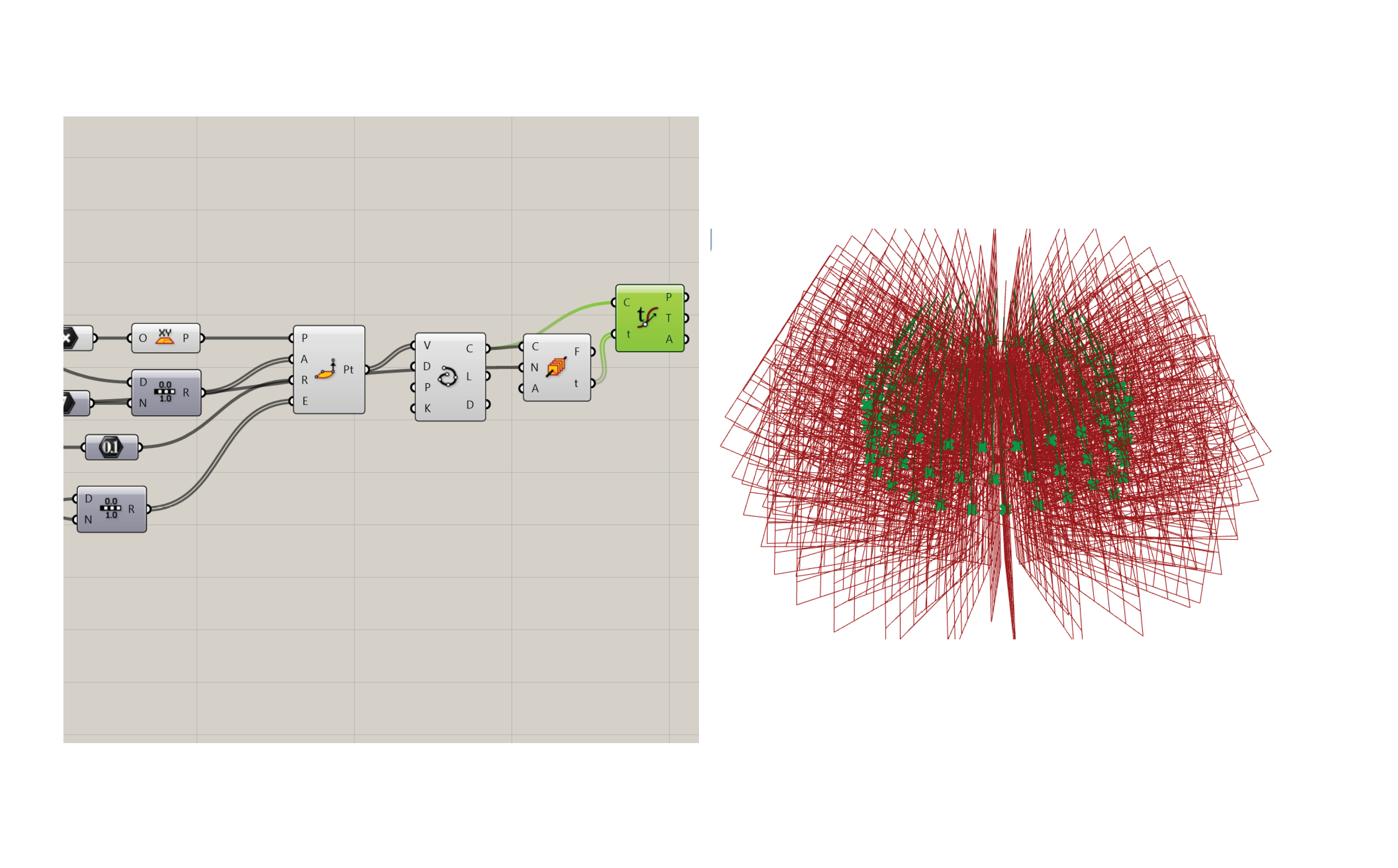
I hid the previous commands so they would not get in the way. Now we need to construct a plane based on the vectors of the existing planes using construct plane. We want the planes to be vertical, so set the Y-axis to be in the Z direction using a unit Z vector.
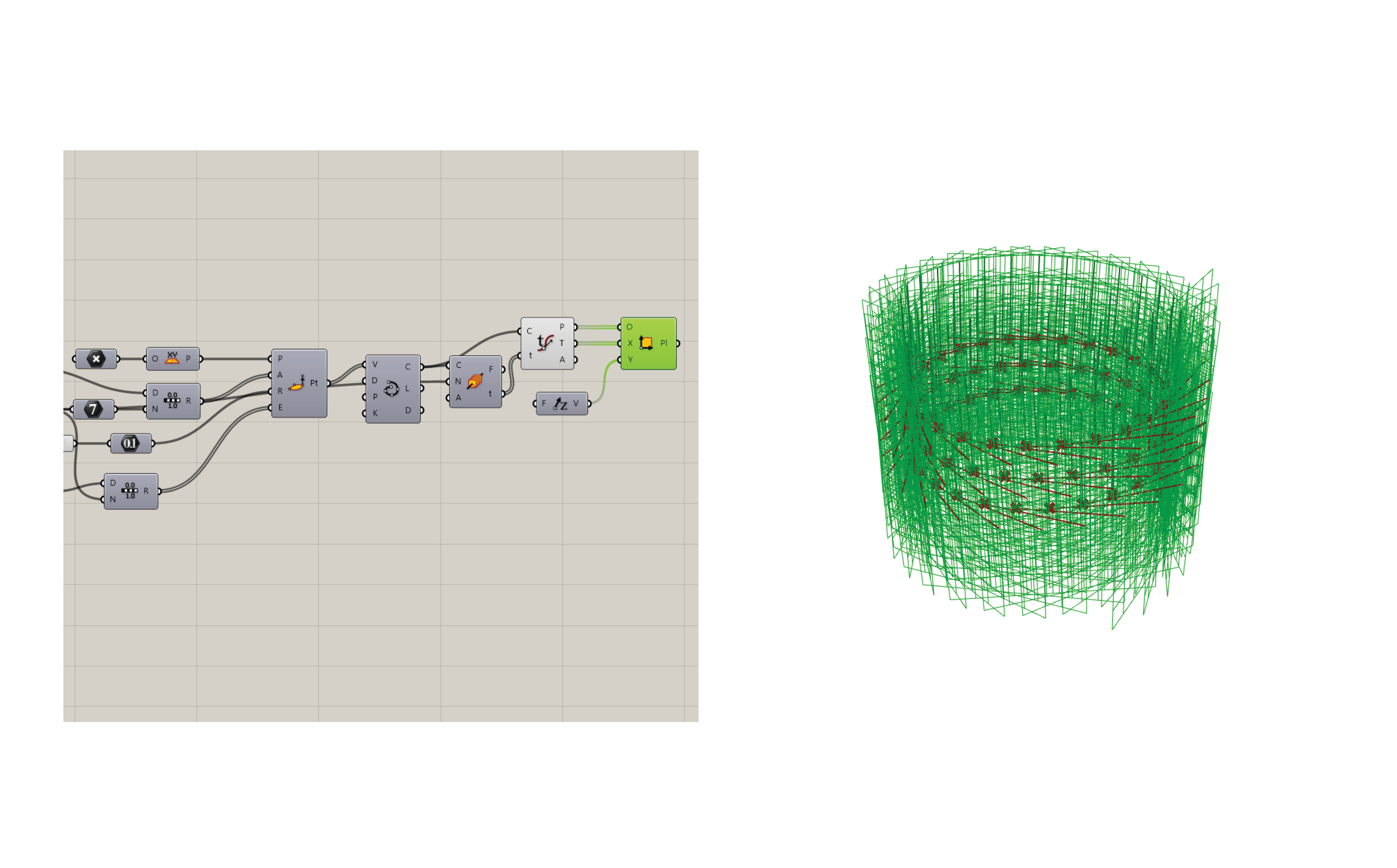
After we have our planes, we will deconstruct their vectors with the Deconstruct Plane component.

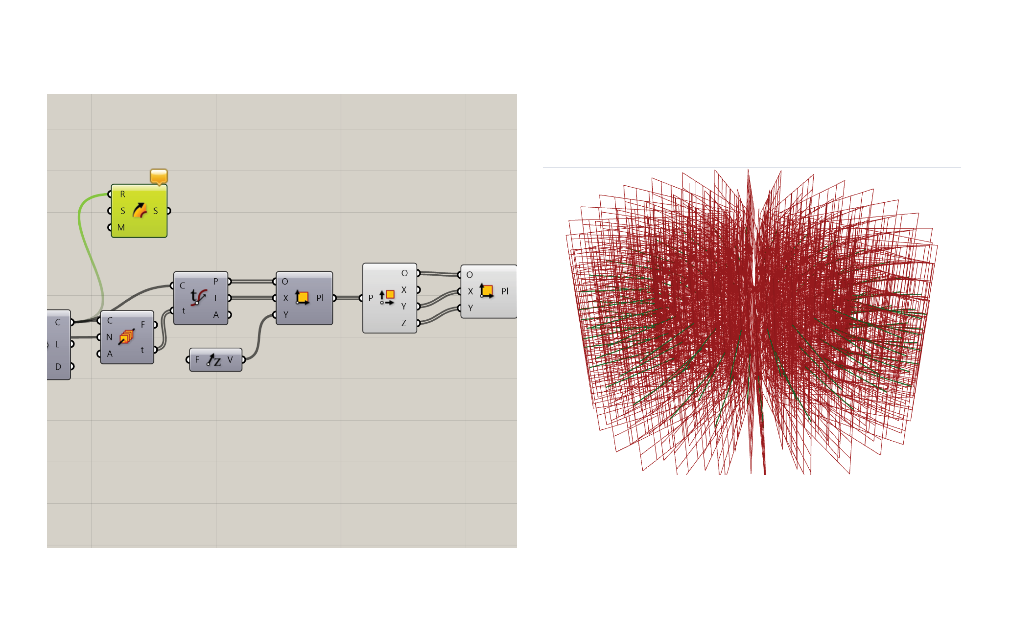
Hide the previous planes. Then we’ll use the construct plane component to rebuild them in the correct direction. What was previously in the Y direction, is reoriented to the X direction, and what was previously in the Z direction is reoriented to the Y direction.

Our planes are all facing the right way, so now we can sweep a profile along the curve to make a form. Use the sweep1 command because there is only one rail. Theoretically, you could use two rails and change the width of the form as it moves. Connect the curve that was interpolated from the points.
You can draw a profile as a curve, or you can create a parametric curve. I used the rectangle component, along with two domains to create an adjustable surface profile. Connect the planes to the plane input of the rectangle to place a section at every point on the curve. Theoretically, you could use a range for the size of the section to transform it as it is swept along the curve. Link the rectangles into the section input of the sweep, and voila!

To add a structure, a polar array will provide you a host of options, both parametric and custom. I used a more custom route by arraying a brep around the same point as the start of the helix. Your column that you are arraying must be modeled where you want it to be on the form. Create a slider for the number and a slider for the angle of the array. Be sure to add this in radians and make the slider maximum 360 as this is the maximum angle of a circle.
This script was very helpful in my studio project, as it allowed me to adapt my ramps much quicker than remodeling the same helix many times in Rhino.
