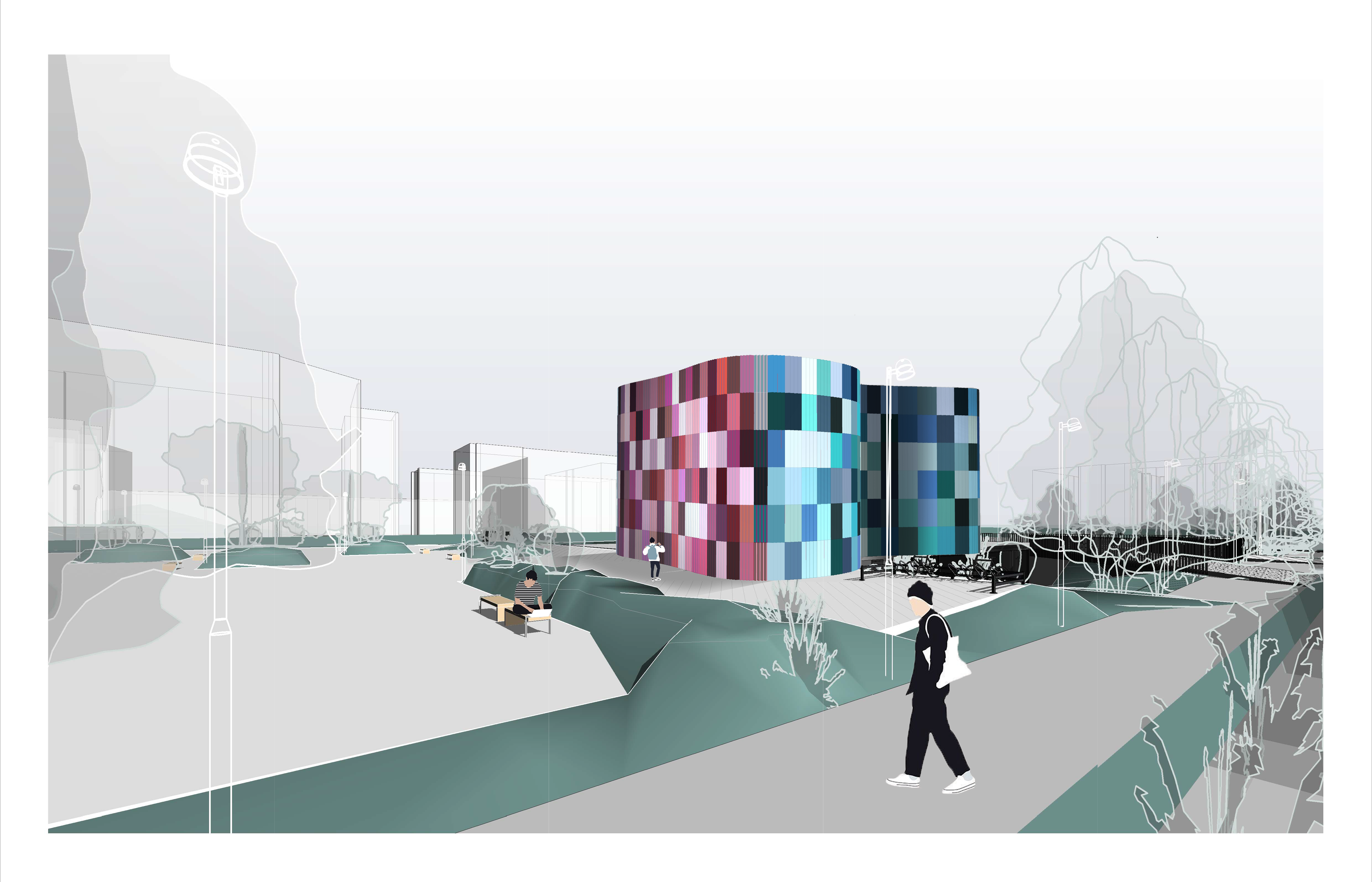
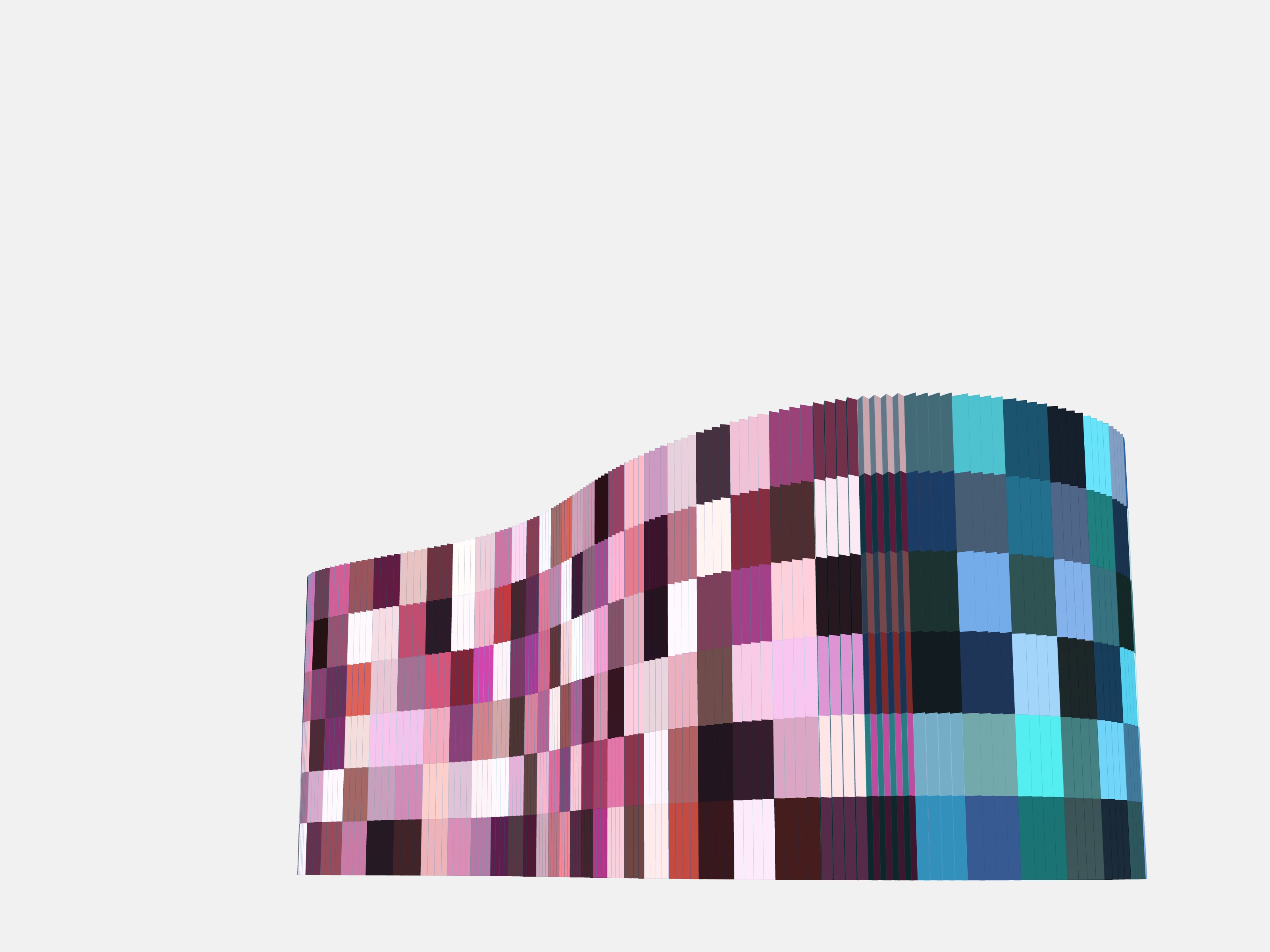
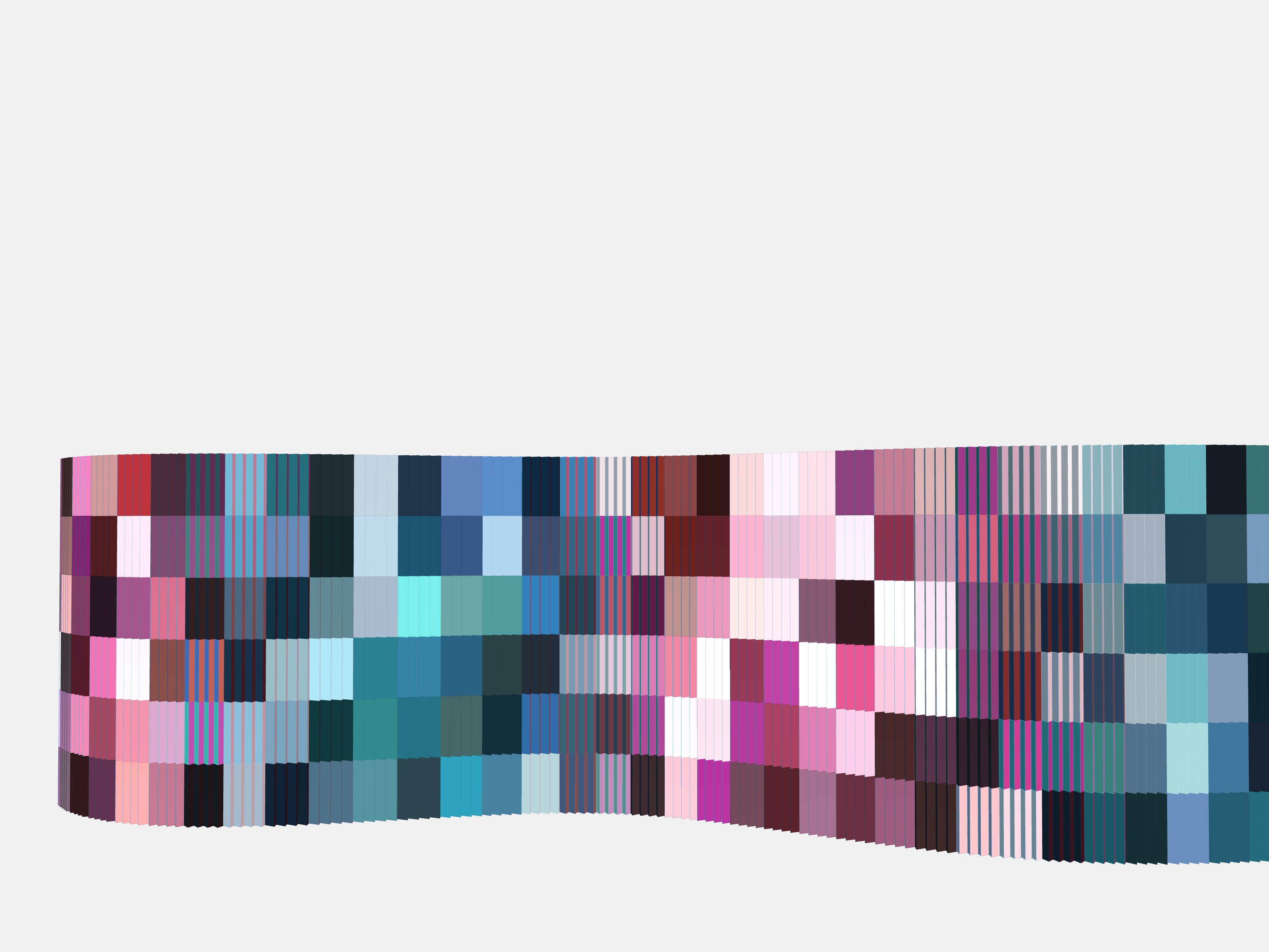
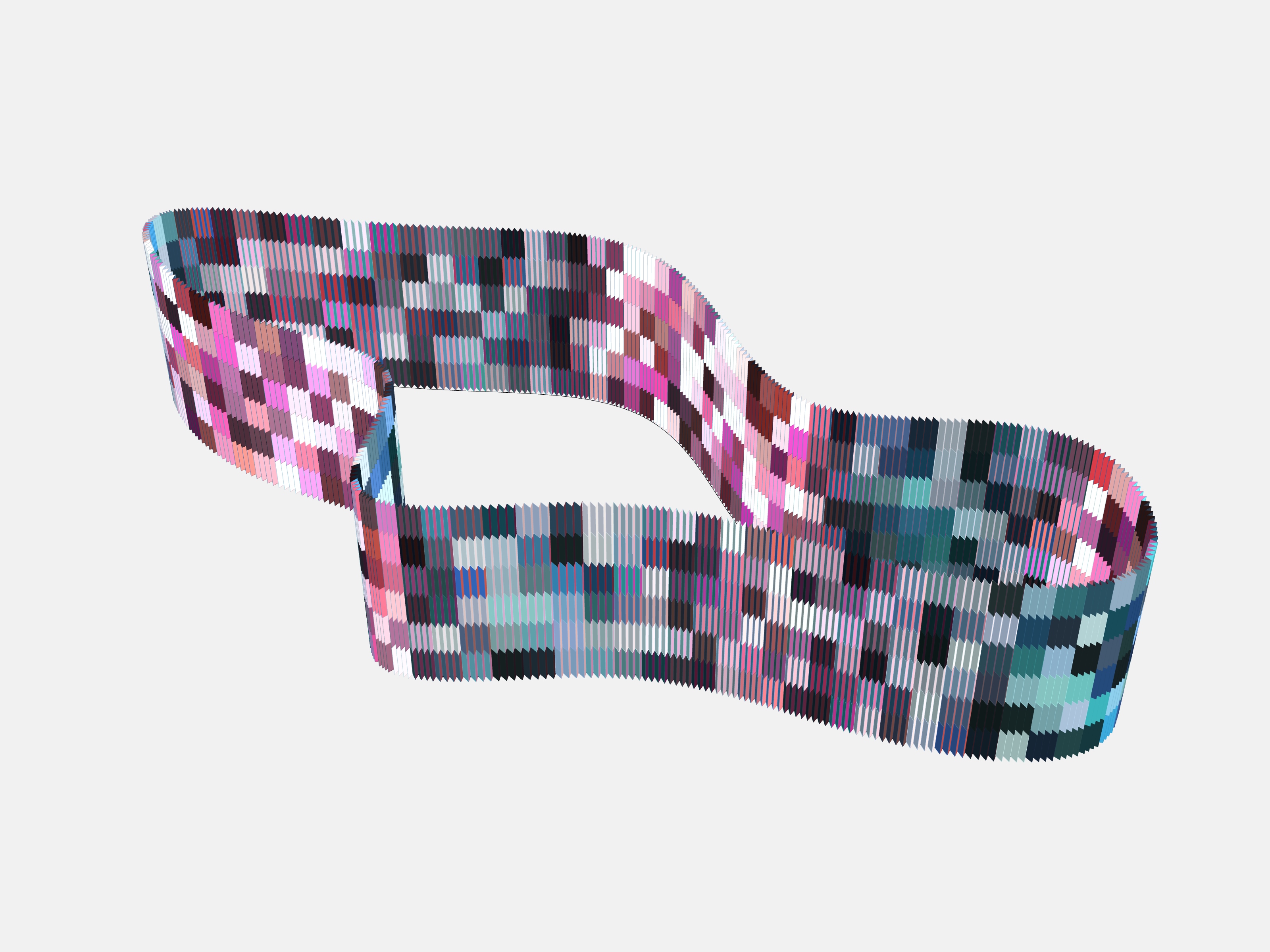
e Goal was to create very visual regulated facade panels, which would display different random tones of one color (for example, shades of red on one side), and contrasting tones of color or any else desired (for example, blue) on the other side, so the appearance of the building would change as you passing by it and keep your mood fun.
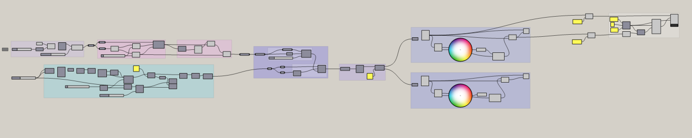
The whole script:
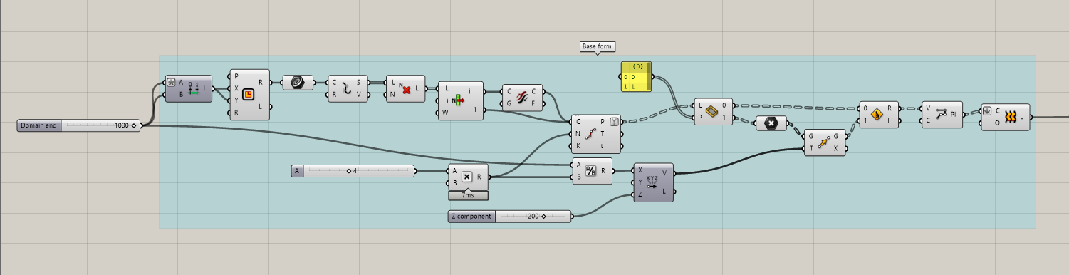
Step 1: To create a base form of facade unit, which can later be relate on a bigger geometry. To do so we have to use “Rectangle” node and parameterize it by using “Construct domain”. Then we have to apply node “Curve” on our rectangle and divide it into segments. Our next goal is to create “Polyline” in “Z” shape to make this facade unit 3D dimensional and be able to see different sides from different angles.To do so we need to remove every Nth element of geometry on a list by using node “CullN”. Then divide curve on equal length segments by using “Divide curve”. To be able to create top points of rectangle we have to divide our main shape node parameter ( “Domain end”) with the desired count of segments ( in our case multiplication B parameter from “Division” input and A parameter ( which is parameter of “Domain end”), then “Move” it by “vector Z” with value of 200 in our case. After creating the polyline we use node “Loft” to make surface of it.
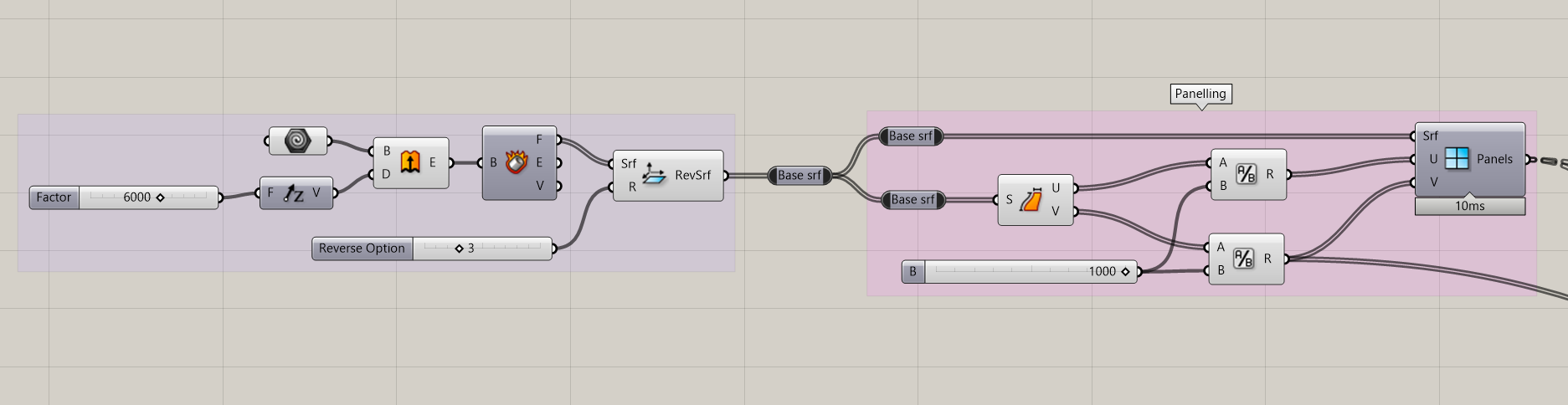
Step 2: The next step is to create paneling on the facade shape. To do that, we have to create and set geometry node first then create quadrangular panels on a surface. To do so we need to get the dimensions of created surface and divide it into panels by using the “Division nodes” on U and V inputs.
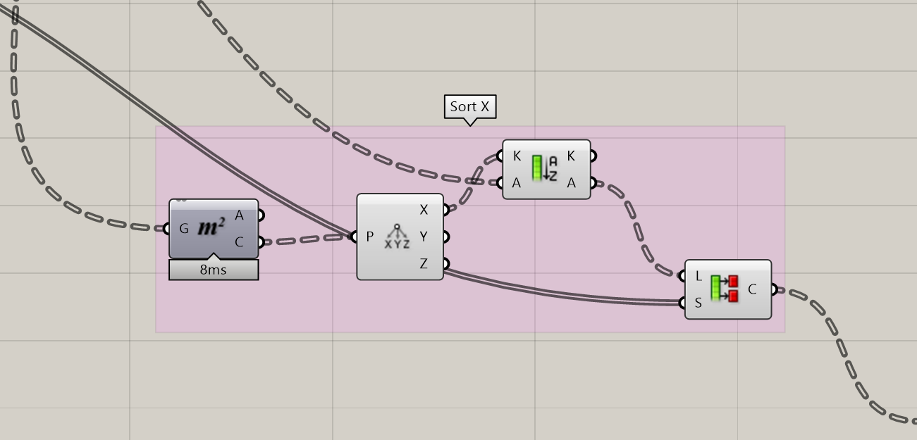
Step 3: Then we have to sort the X components of each unit of the geometry by finding the centers with node “Area” and “Deconstruct point”. After that we would “Sort a list”. The last step in this box would be to part our list into sub lists by using “Partition list”. As “Size” input we would use a result of a division V parameter of “panels” node. The result we would relay.
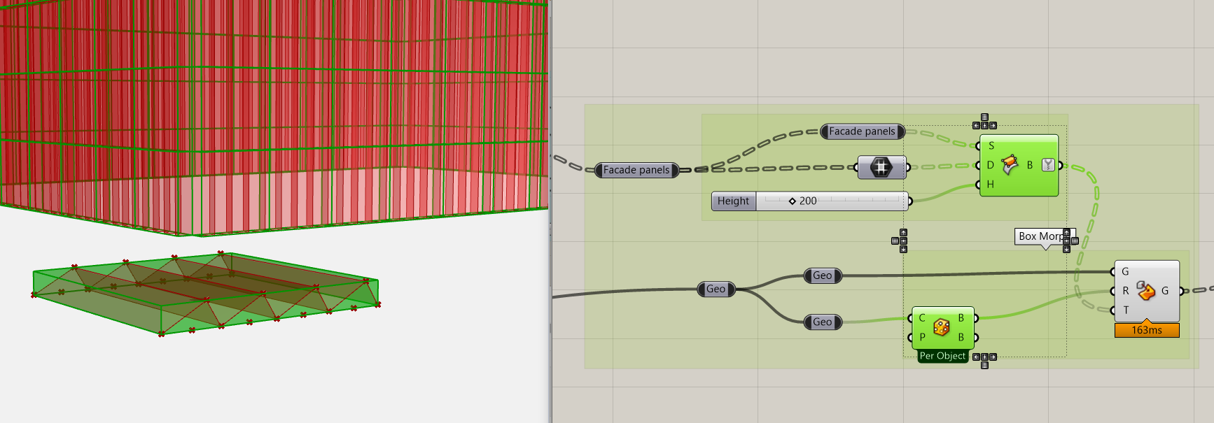
Step 4: Next we would morph an object into a twisted box. In our case we create “Surface box” node with hep of inputs like “Facade panels” – Surface, “Domain” from the same node “Facade panels” and desired “Number slider” parameter of height. Then we place an output of it into a Target input of “ Box Morph”. As a Reference box we wold use “Bounding box” from our main geometry of the facade unit, which we created in the first step.
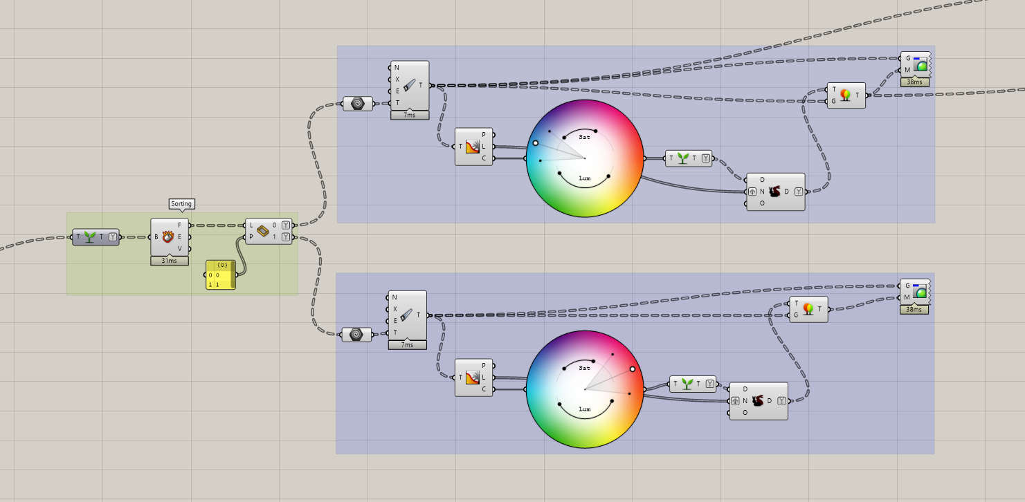
Step 5: After we would apply an output of a “Box Morph” into the “Graph Tree” node. In the next part we would use a“Deconstruct Brep” and use a output list of it on the node “Sift pattern”. This one is basically spiting our one list of faces into two lists, what we would like to set in two contrast colors. Next we would use a “Color wheel” for each side, and create two separate “Grafts”.
vualá:
This is what we get in the result.
Grasshoper file:
RusenkoA_Keep it fun_Facade system