
CAD Tutorial download all files
This tutorial topic was inspired by one of Ondrej Zunka’s – a well-known Czech digital artists- art pieces exhibited in the framework of The Invisible Forces exhibition which took place in Kunsthalle, Prague.
This tutorial will present a façade panel with variations based on different minimla surfaces – Gyroid and Scherk’s surface.
First variant. Chromodoris method
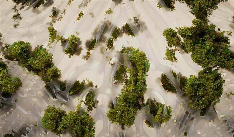
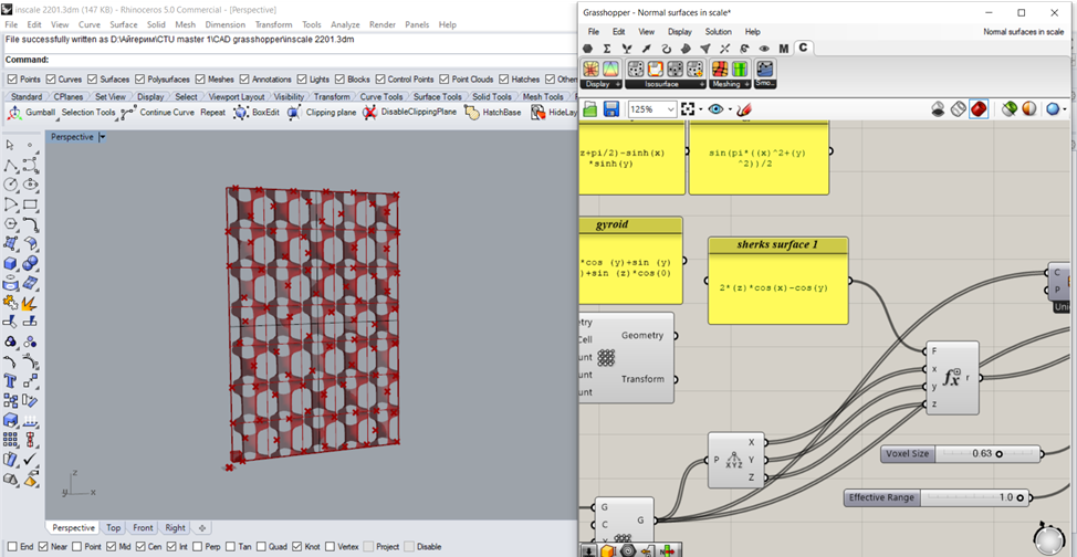
- Choose a suitable equation of gyroid . Create an isosurface that is generated through a gyroid equation
In panel copy the equation sin(x)cos(y) + sin(y)cos(z) + sin(z)cos(x) – from Wikipedia. Set one point in Rhino. Do a box array at this point. Plug that into your XYZ to have a field of points which is how we’re create the isosurface . Deconstruct the points.
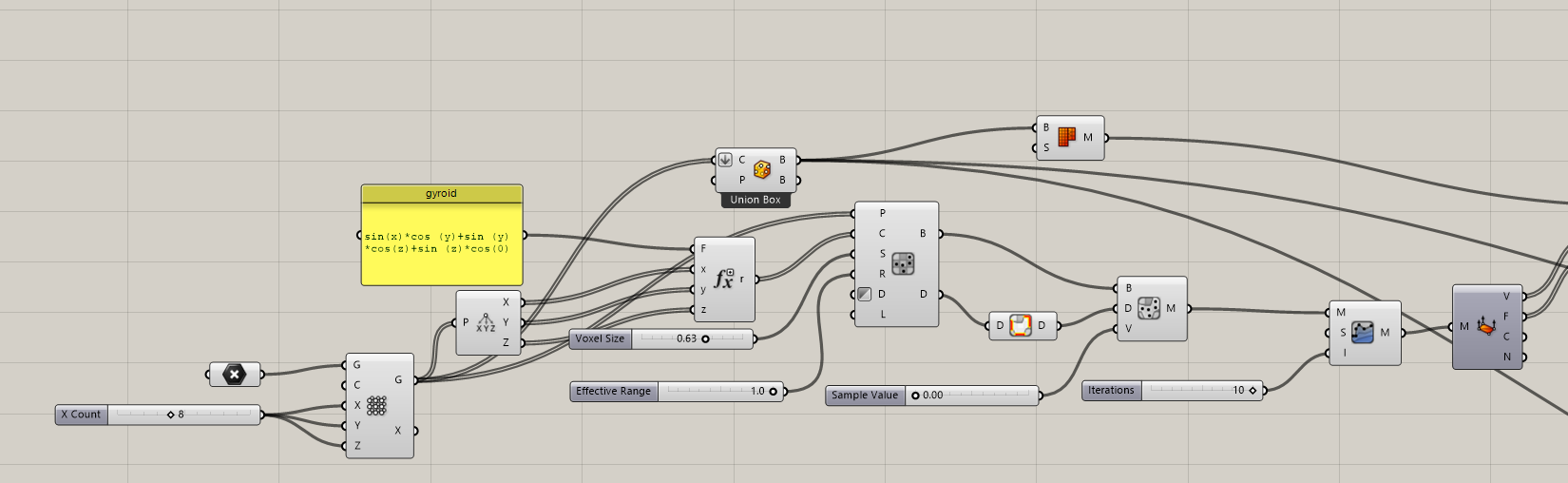
Type in Evaluate in grasshopper and plug in each of the previous outputs . You can click on + sign to add Z component. Imp: make sure the variable X , Y and Z are named the same in components.
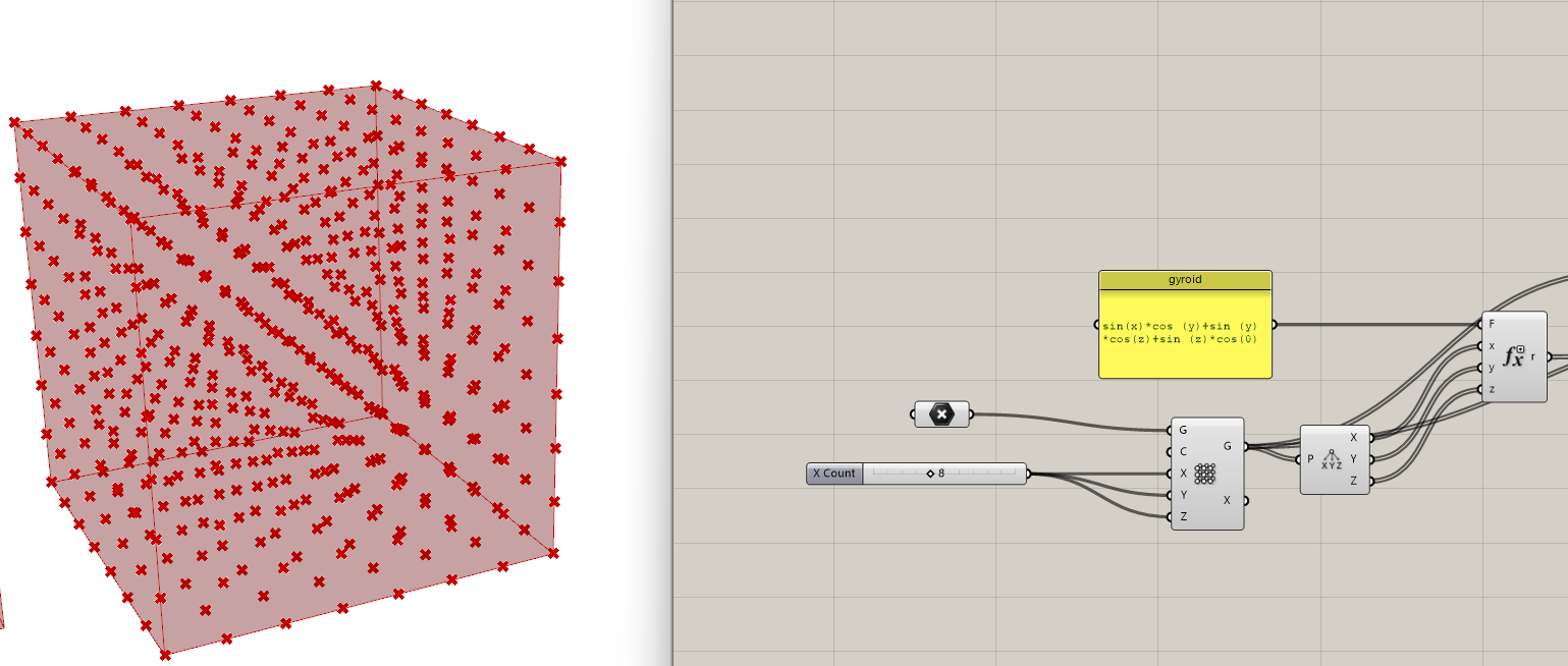
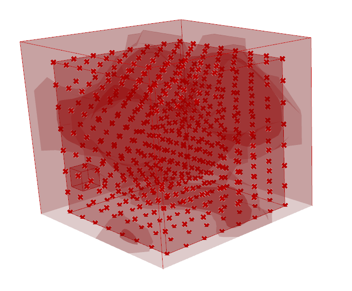
Download Chromodoris . Click C on the panel to open Chromodoris and in the isosurface tab choose Sample voxels. Sampled points will be from Box Array. The result of the Evaluate goes into charges. Define a Voxel size. 0.25. Invert Density sampling. Effective range is a searching distance within the isosurface.
Drop Built Isosurface to a grasshopper canvas plug in the voxels as the bounding box. Voxel data enables to create that isosurface. Evaluate the sample value at zero because the gyroid equation equals zero. Smooth the gyroid with QuickSmooth component. Set iterations (10). This is how you get a mesh.
2. Map the gyroid on the surface.
In Rhino make a simple rectangular surface. Divide it into U and V directions with Construct domain. Important is to use equal numbers ( ex; 5 , 6) . Then I morphed the solid (gyroid) to a surface using Box Morph tools and joined the mesh.
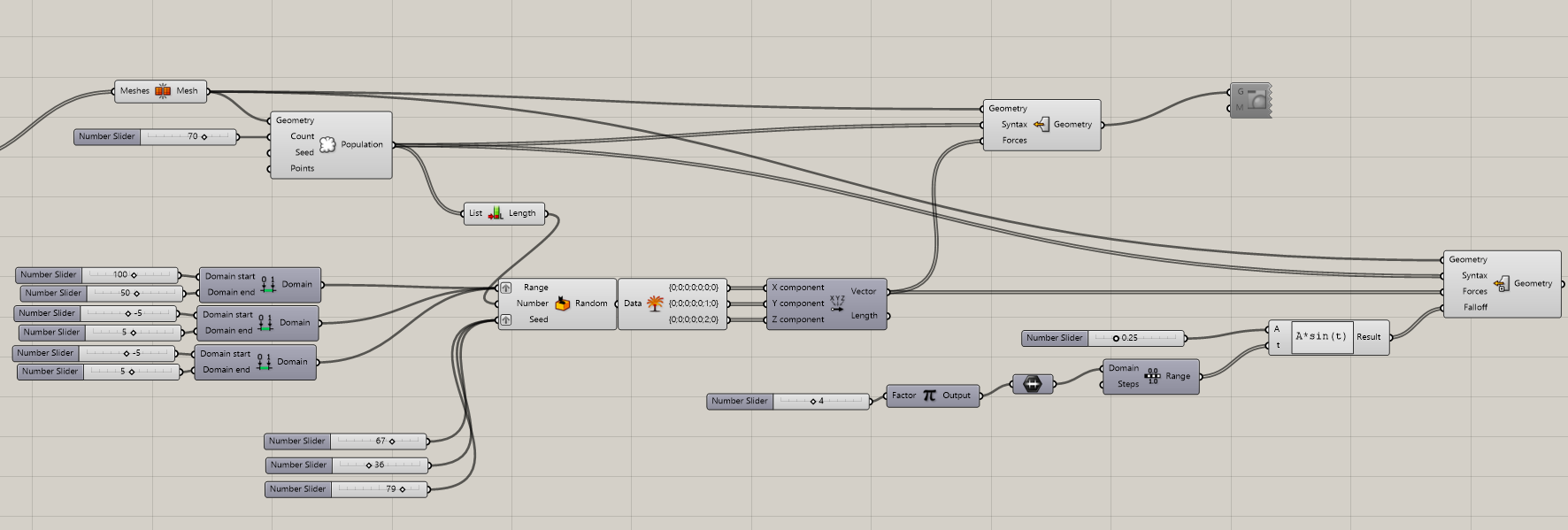
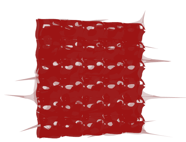
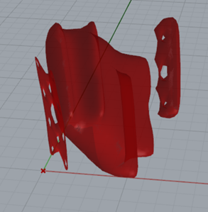
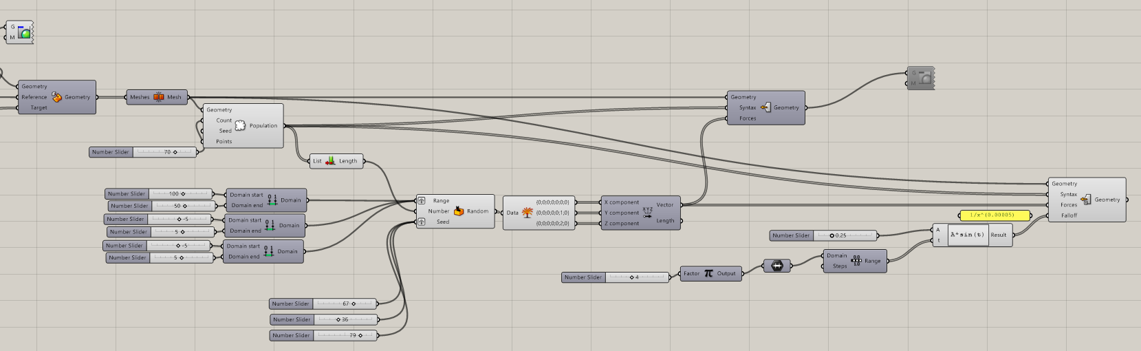
3. Deform the surface to a desired goal
Populate a number of points on a surface. The aim was to give the surface a number of reference points and vectors to move them in deferent directions to get a desired shape. I also tried to use custom spatial deform with a fall of . However to deform the surface in grasshopper through another equations slowed the script . It limited the possibilities for different deformations due to heavy and slow performance.
During consultations the following problems were found 1) the form of the gyroid I made was not suitable to map on the plane . The reason is that gyroids are the type of minimal surfaces that work in 3 dimensions. I had to use a surafce more “flat” and repetitive 2) Chromodoris was not the most effective way to build an isosurface and the shape did not look ideal. 3) It was more effective to deform the final mesh into a desired shape manually in Rhino using CageEdit command .
After a short research of the nature of the minimal surface I found a suitable one – Shrek’s surface Exp(z)*cos(x)-cos(y) – minimal surface which is doubly periodic meaning it is invariant under two linearly independent translations.
The result was still questionable. Therefore I was suggested to built the initial minimal surface via another plugin – Millipede.
Second Variant. Final . Millipede
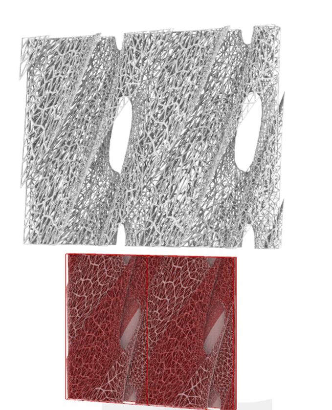
Chromodoris and voxels method was not ideal. I rebuilt the script using Millipede plugin instead , which helped to built an isosurface based on the Sherk’s surface 2 equation. As a result I got much lighter script and easier steps to follow.
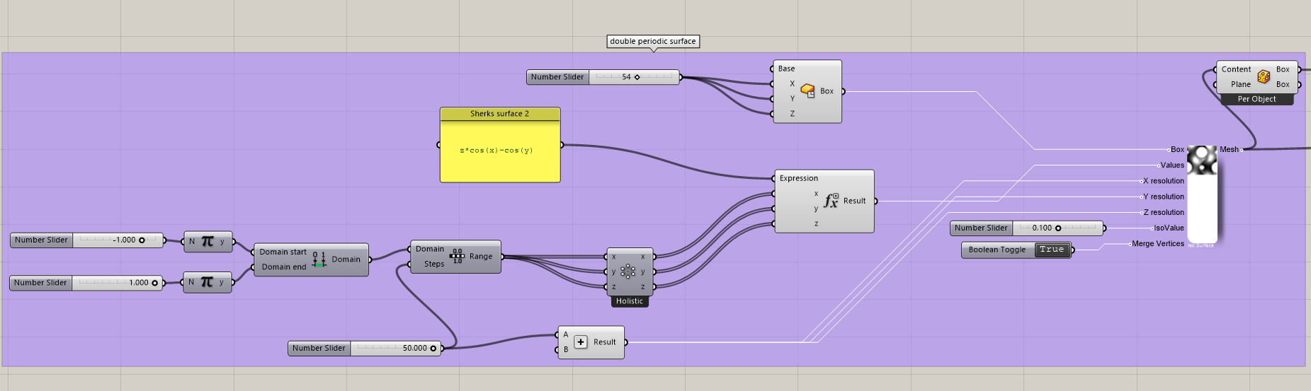
- Download Millipede. Build a desired minimal surface using Millipede
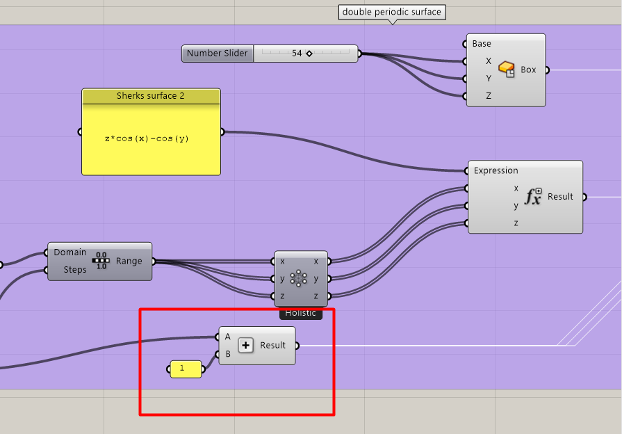
Find an Isosurface tool in the Millipedes’ geometry section. Set a math section , select Evaluate tool. Add Z variable. Type z*cos(x)-cos(y) into the panel. Give it to the Expression.
Click Range. Set domain -Pi to Pi. since we are using sinx and conx. To define X, Y and Z set number of steps – 50. Use cross reference tool which can be combined to produce cloud of points . To have 3 inputs click on + to add Z . Plug in X,Y,Z to Expression. The result will be the Value of Isosurface.
Click Center Box from Primitives. Give it the same number to X,Y,Z . Plug it in the Box.
To set X,Y,Z resolution we need to add it up by 1. Choose Add from Math section. Give it to X,Y,Z resolution.
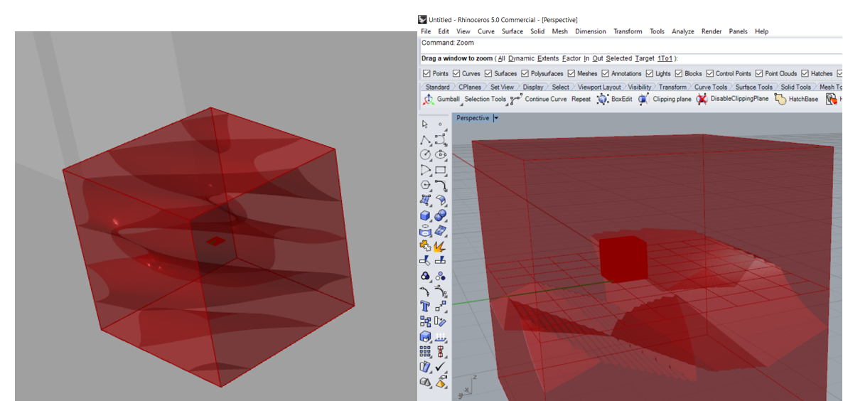
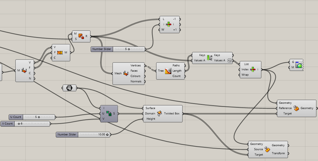
2. Model a surface in Rhino and map the Scherks surface using Reference Box and Weavwebird plugin.
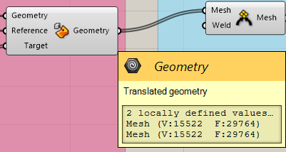
Create a surface in Rhino. Set it in Grasshopper. Click on Box Morph. Plugin mesh to the Bounding box to use it as reference. Surface Box tool is a method to deform it . Use Divide Domain 2 to divide the surface into equal sizes. We can define how many section to have in U and V domain. Set the number for Height which will be the thickness of the façade panel . Give the Twisted Box to the target.
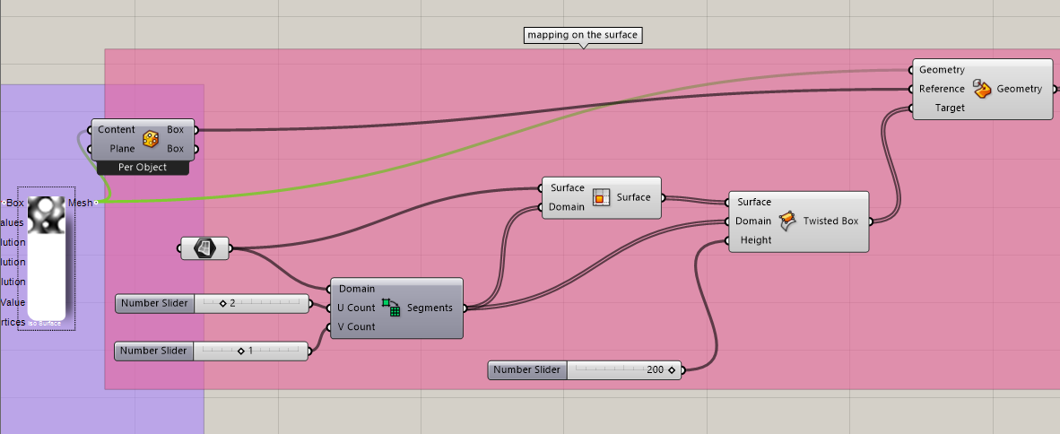
3. To join I used Weaverbird Weld .
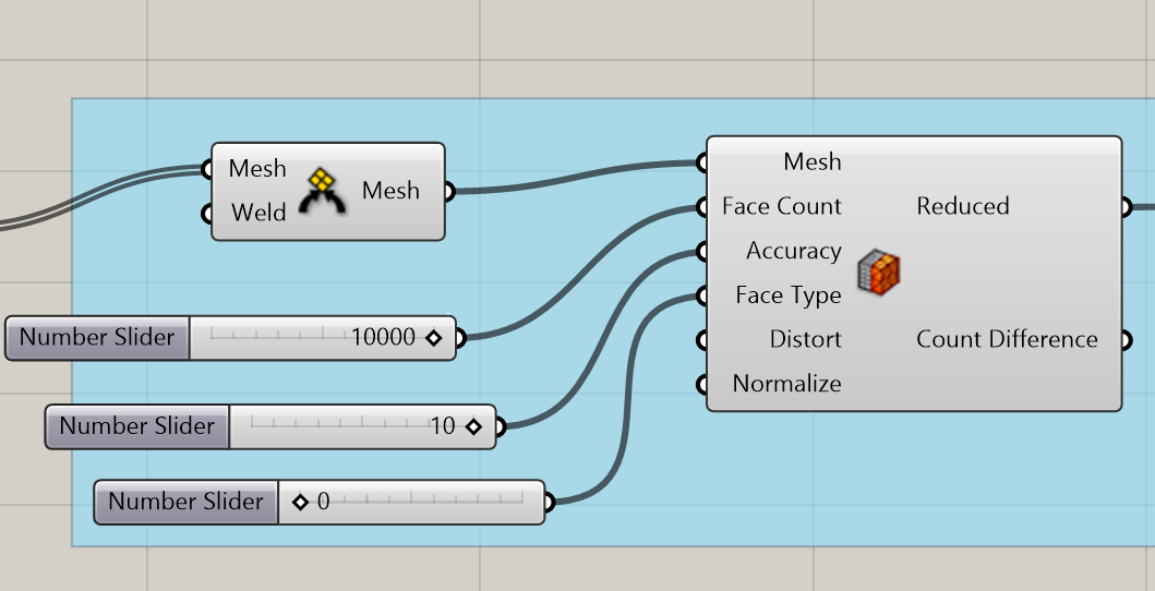
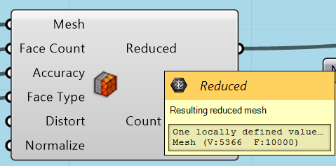
I tried to reduce the mesh.
REVISE THE SCRIPT IF YOU HAVE PROBLEMS
3*. The problem I had was that the mesh had little gaps in between all the meshes even with welding weaver plug in. When I tried to connect each points of meshes between with Puffer fish plug in it produces unwanted artefacts . Turned out It was a “range +1 problem”. I rushed through this step and did not think properly in the beginning trying to use Addition component to all the Resolution inputs of milipede.
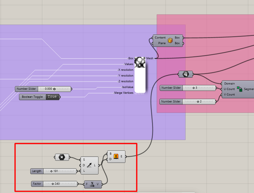
3** Also by adding Extrude components , setting a point and placing it on the surface can be useful.
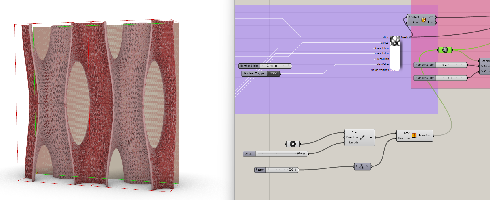
This also improved the performance of the Reduce mesh since it is one big connected mesh without gaps.
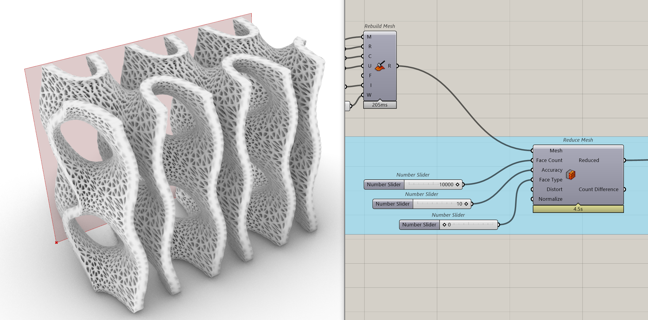
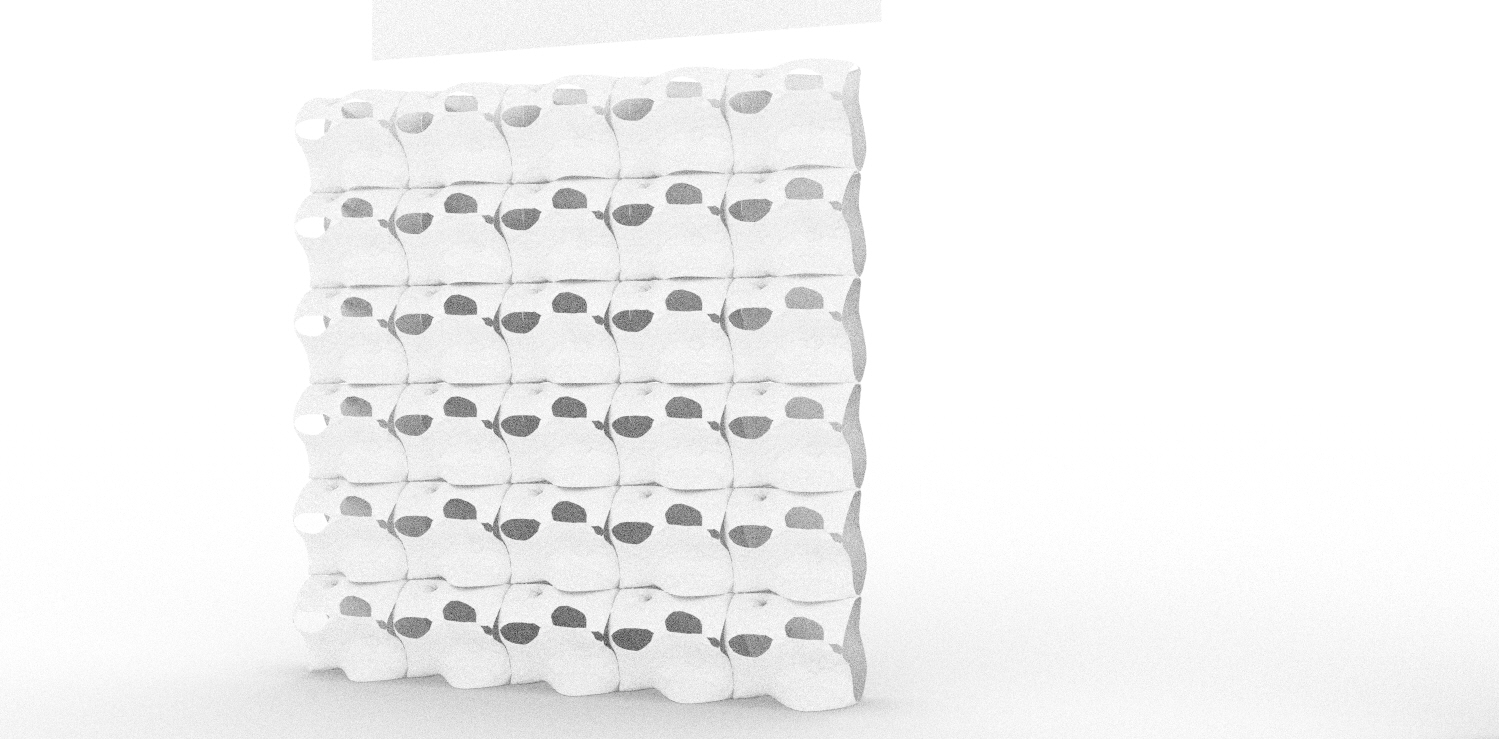
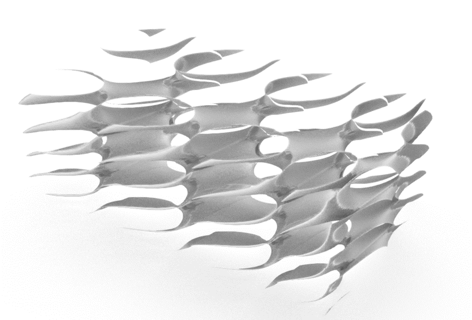
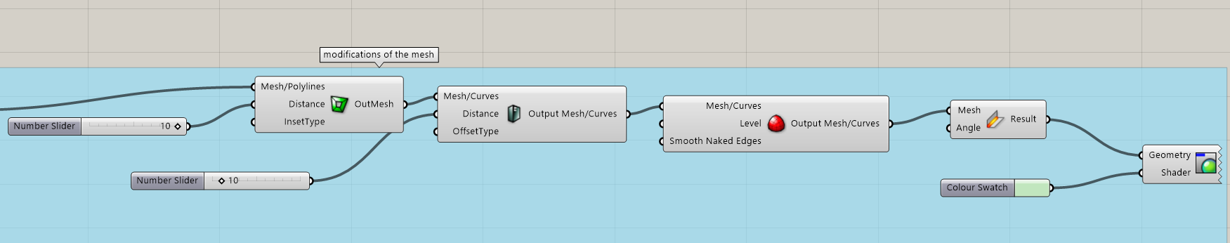
4. Thicken the mesh, sooth it – modify with weaverbird tools.
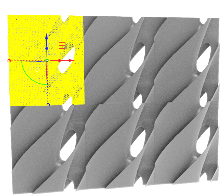
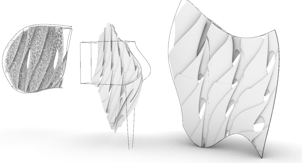
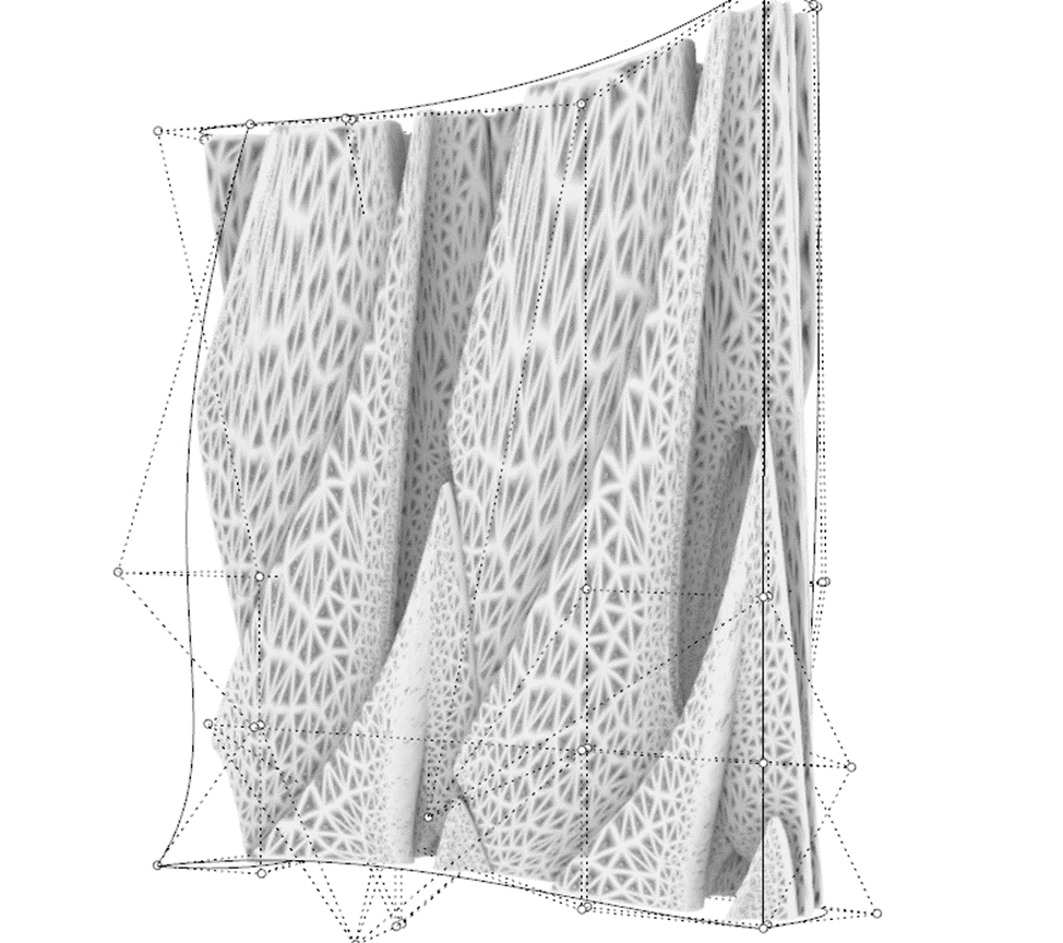
5. When you decide on the shape you like you can bake the surface. Then manually stretch the mesh in Rhino using CageEdit command.
Type CageCommand. Click on Bounding Box – Enter. Pull the points to different directions.
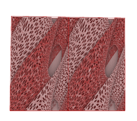
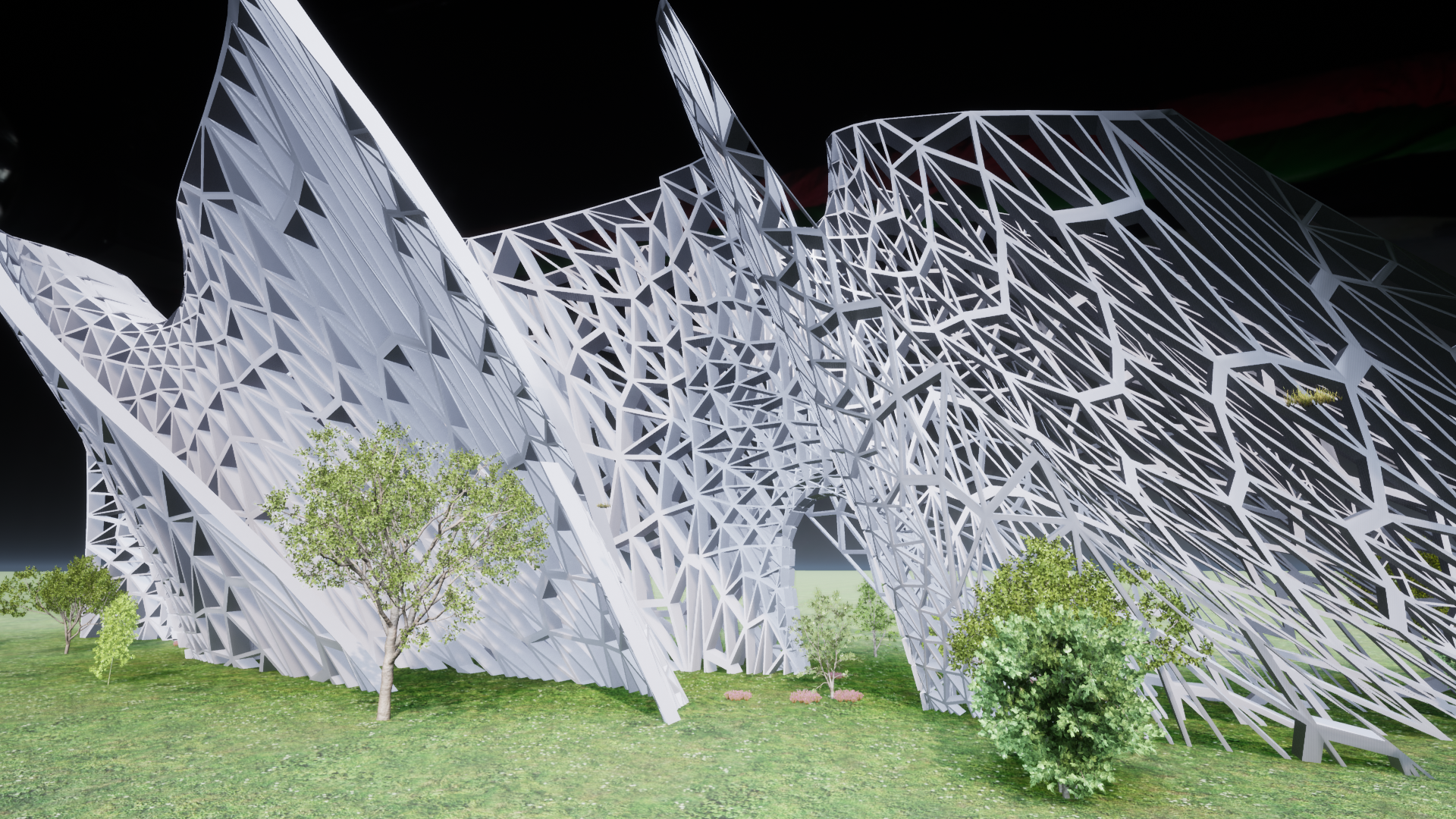
6. Render in Twinmotion.
After testing out different ways to change the initial shape I chose one and imported the 3ds. file from Rhino to Twinmotion .
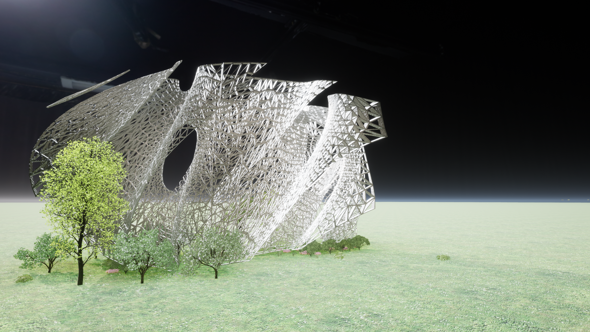
That method of building surfaces could be beneficial for finding different new forms mathematics based façade panels or pavilions.
For this tutorial I used :
https://wewanttolearn.wordpress.com/tag/gyroid/
Aigerim Azirkhanova. 1st year international master. FA . 500CAD3