
THE SPIRAL BAR
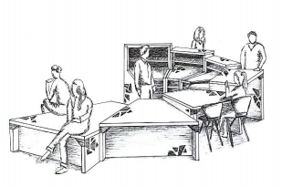
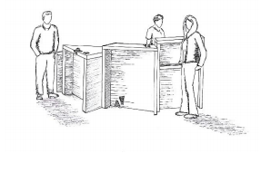
During the past semester, one of my design studios was about creating a bar. I made a spiral bar inspired by the golden ratio. In grasshopper, I wanted to really use the ϕ (the golden ratio constant) instead of only using it as an inspiration. To create the bar in 3D with grasshopper, I will use a lot of mathematical formulas.

GENERAL
A great benefit of Grasshopper is the possibility of using mathematics. In this tutorial, I will show you how to use mathematical formulas to create a 3D volume. I wanted to create a spiral bar based on the golden section. The 2D shape of the bar is created by three different polylines. I will explain each of them step by step. After creating the 2D figure, we will also extrude it and use variable heights.
DEFINING GOLDEN SECTION AND INNER POLYLINE
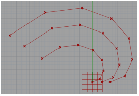
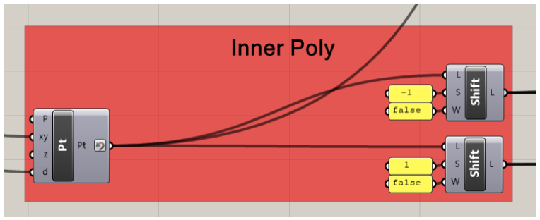
We define the points on the golden spiral by using polar coordinates. Because the points spiral around the origin it is better to use polar points instead of the usual construct point xyz. To create the golden spiral, we start with creating a regular circle. The formula for a full circle is 2πr. So we connect a range component to the polar point component. The range component has two inputs. The Domain (D) and Steps (N). The domain is defined by a multiple of Pi(π). 1xPi defines half a circle, 2xPi a full circle, and so on. The number of steps defines the amount of segments on the curve. Because we don’t want to create a regular circle but a golden spiral, we need to insert Phi (ϕ, the golden ratio constant). We connect Phi to the offset parameter of the polar coordinates component. By doing this the distance between the origin and each point increases. By rotating and increasing the distance between the origin and each point, we get a spiral. We will be using a lot of shift list components in this project. A shift list outputs a list of points/ lines/ surfaces. A shift list has 3 inputs L (List), S (Offset), W (Wrap). The offset is the first point of the list. If wrap is false, the points with lower index than the offset will we deleted. If wrap is true, the points with a lower index than the offset will be added to the end of the list. The first shift-list outputs the polar points. The second shift-list outputs the polar points in starting with the 2nd point (index 1), and removes the 1st point (index 0). By connecting the first and second shift list with a line component, the golden spiral is drawn.


OUTER POLYLINE
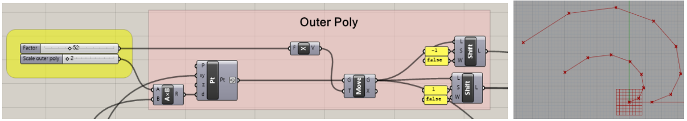
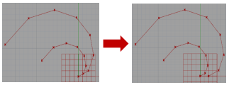
For the outer polyline, we also use a polar point component with the same input for the xy-parameter. By doing this, we have the same amount of points on the second curve. The distance(d) parameter is connected with a multiple of Phi, this is how we scale the outer polyline. Because the first point of the this polyline doesn’t need to start on the origin, we move the line along the x-axis. We use two shift lists in the same way as the shift lists of the first polyline.
ANGLE POLYLINE
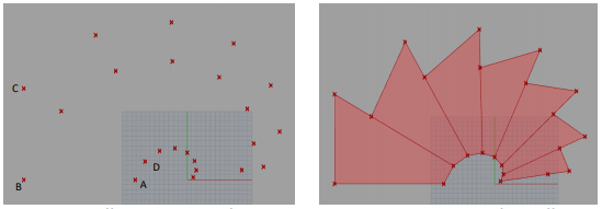
The third polyline defines the angle and has to be in between the first and second curve. To find a point in between two points we use the following formula: 1/2 = . 1 + (1 − ). 2 where 0 ≤ u ≥ 1<. The shift list returns all points on this curve.

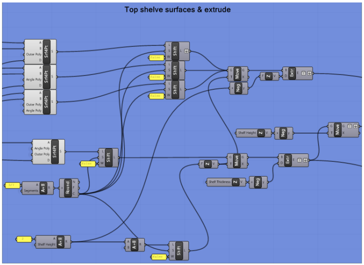
BAR TOP SURFACE AND EXTRUDE
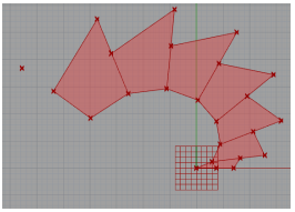
To create the different segments of the bar we need to connect the points of the different lines. For this we use a 4 points surface component. We connect a list of points to each input (A, B, C, D), by doing this we create different surfaces.
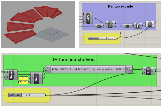
First we want to move the different surfaces and give them all the same height. To do this we use the move component. After doing this we want to set the thickness of the bar top. We do this by extruding the surface in the (negative) Z-direction.

The next step is to give each surface a different height. To do this we us a range component connected to a list. The range component gives the number of the surface (1, 2, 3, 4, …). Each surface will be 15 units higher than the surface before because we use a multiply component.

It is also possible to several surfaces with the same height. The first 3/7th surfaces need to be 90 units high, the next 2/7th need to be 75 units high, the next 1/7th need to be 60 units high, the remaining surfaces need to be 45 units high. To do this we use an expression component. In this expression we use If functions. We can set a condition. Depending if this is true or false, the output will be different. For this configuration we use three if statements.
BAR SHELVES SURFACES AND EXTRUDE
The bar shelves have to be smaller than the bar top. We define new points in between the inner polyline and the angle polyline. This is done the same way as the angle polyline.
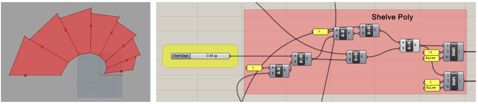
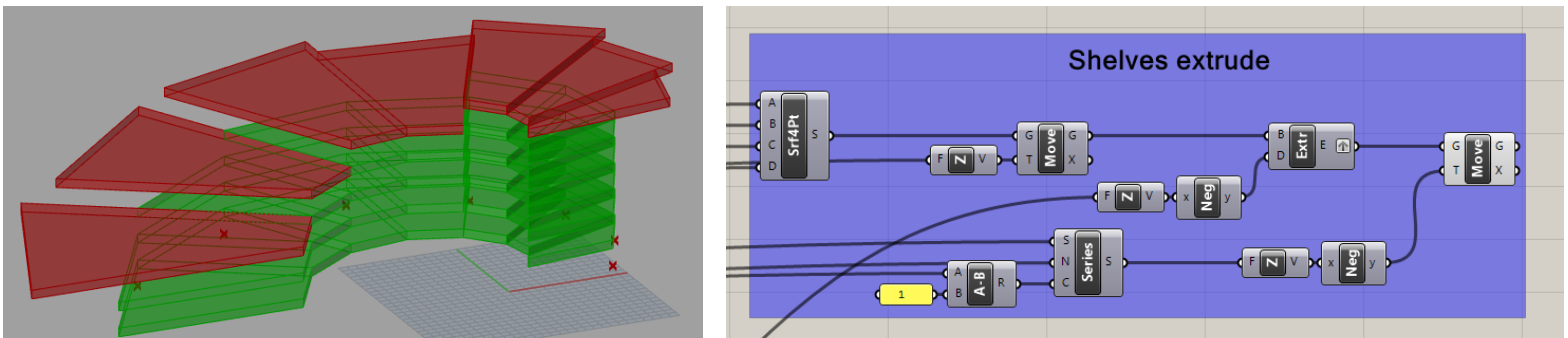
We use a 4 points surface component to create the shelf surface. We move and extrude the shelf the same way as the table top. Because we want more than one shelve in each segment, we use a series component. We connect the series component to the if statement we used before. By doing this we can move each surface multiple times in the negative Z-direction.
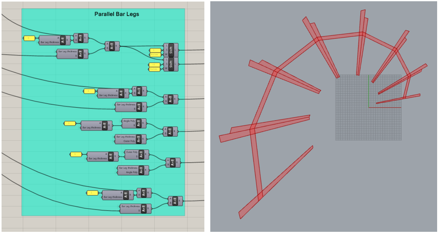
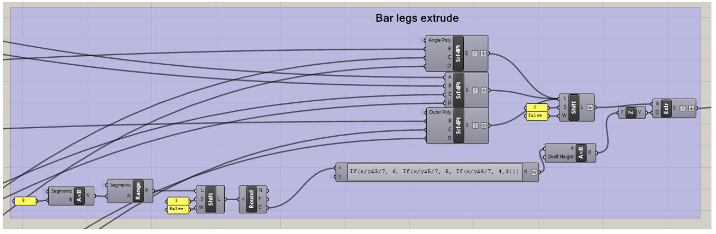
BAR LEGS
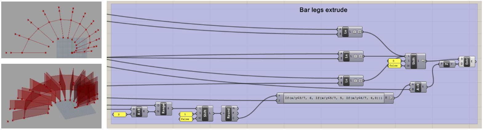
Each bar segment has 3 legs with the same height. First we draw the lines for the legs. We join the three different line components in a shift list. Because we want to group the lines for each segment. We first Graft all the line outputs, then we flatten the shift list output. We use an If expression in the same way as before to set the height of the legs. Because the legs need to have a thickness, we draw parallel lines for each bar leg. We remove the line components and replace them by 4point surface components.
BAR TOP SHELVES
To create the bar top shelves we use the same techniques as before. First we draw the points that will define the corners of the shelves.
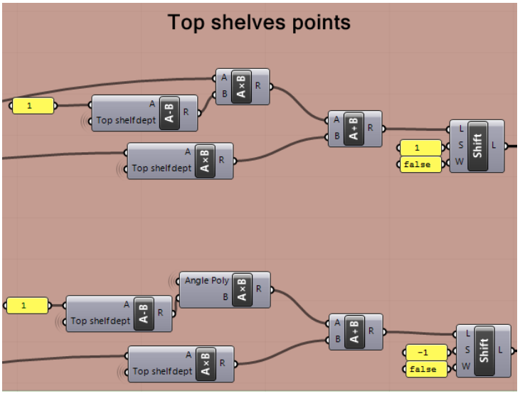
Next we draw parallel points so that we can draw the surfaces of the bar shelves.

The last step is to extrude them. We use the same If function as before to define which segments get a shelve.
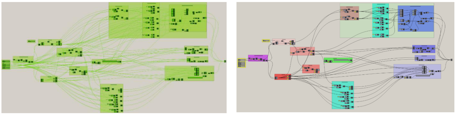
CLEANING UP THE SCRIPT
Most of the lines coming from the different sliders are hidden. The inputs of the components where the sliders go to are given the same name as the slider. Only the important lines are kept visible. Creating groups and giving them a specific colour and name helps to keep a better overview of the project
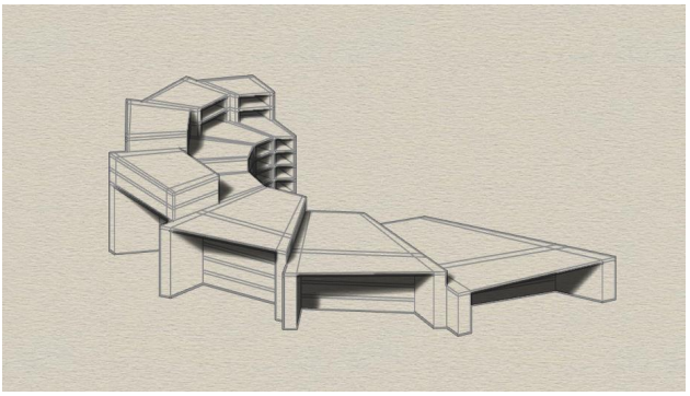
FINAL RESULT

To read the full tutorial, click on the following link:
To download the whole script, click on the following link: