Goals of Tutorial
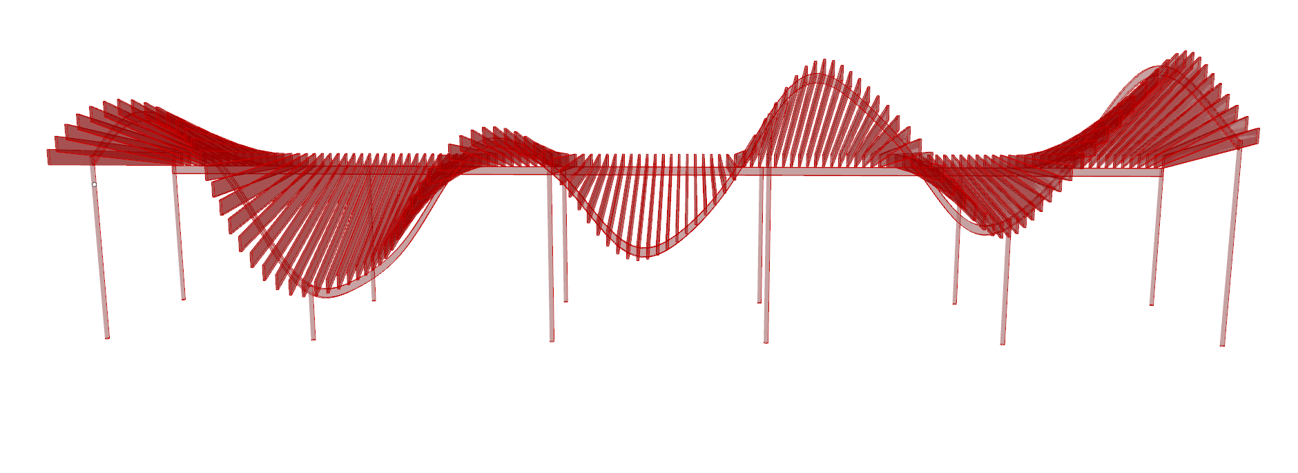
- Using multiple graphmapper components to create undulating effects in the horizontal and vertical direction in a canopy design. A linear array will be used with this to model multiple beams that follow the pattern created by the graphmappers.
- Interpolating curves to create support structure for the canopy.
- Using the OpenNest plugin to determine efficient ways to cut beams out of plywood sheet material.
Files and Links
- Grasshopper File: Final
- Rhino File: Final Tutorial
- OpenNest plug in: https://www.food4rhino.com/app/opennest
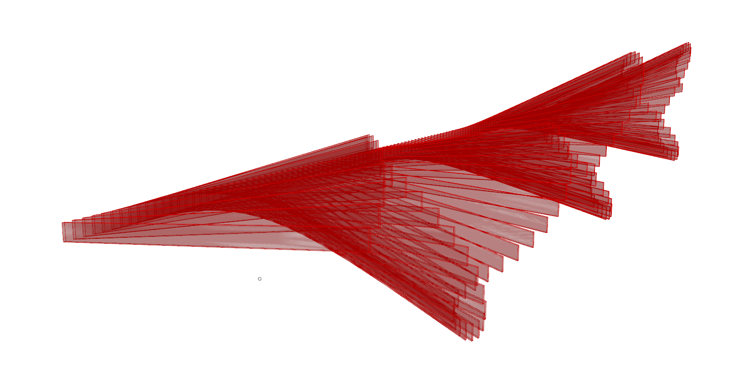
Creating the Beams
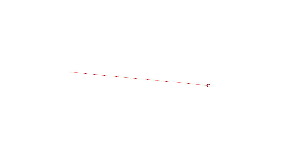
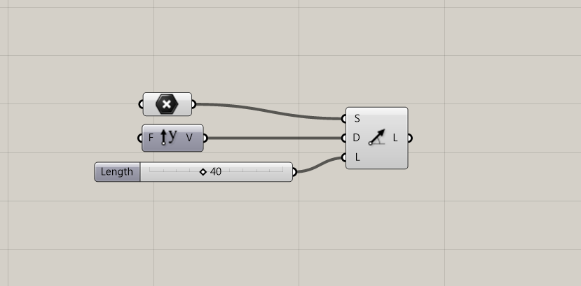
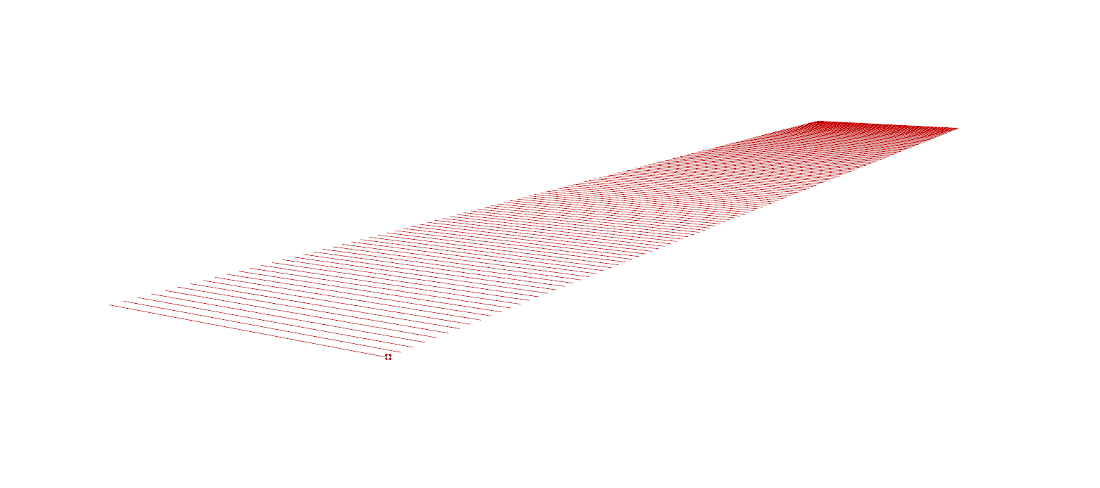
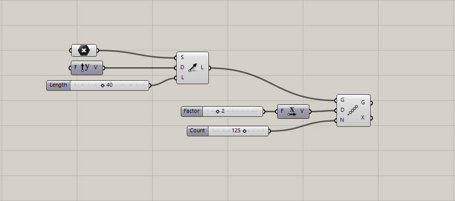
- Use the Line SDL component to make the initial line. You’ll have to assign a point for the line to start at, plug in Unit Y into Direction, and add a slider for the length.
- Plug that component into the Linear Array component. Plug a slider and the Unit X component into Direction to control the spacing of the array. Also use a slider for the Count input to control the number of lines.
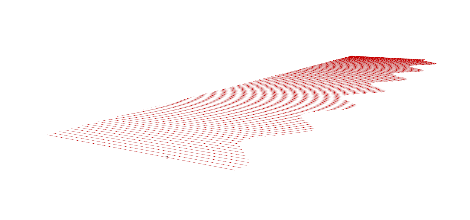
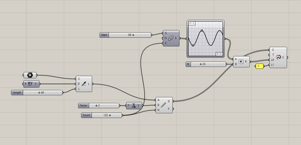
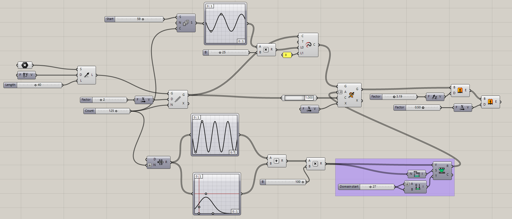
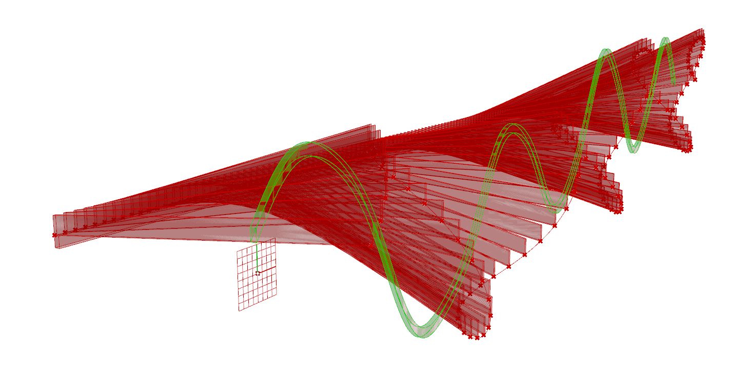
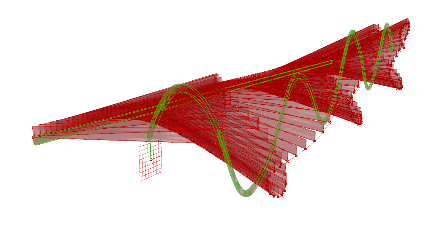
- In order to make the lines undulate on the horizontal plane, you’ll have to use a Graphmapper component. Create a Series component and plug that into a Graphmapper. Make the graph a sine graph and adjust as you wish. Plug a slider into the Start input of the Series component to change how the array starts. To create a greater effect, plug the graph into a Multiplication component. Use a slider in the B input to multiply with the graph. Finally, plug that into the L0 input of an Extend Curve component and a ‘0” into the L1 input. Plug the geometry from the Linear Array into the Extend Curve to see how it affects the lines.
- Next create the graphs for movement in the vertical direction. Take the slider controlling the number of lines and plug it into the Steps input of a Range component. Make the Steps input an expression. Plug the Range component into two graphs. They can be different graph types, but I use a Sine and Gaussian graph. Adjust both graphs and then plug them both into an Addition component. Similarly to the last graph, plug the Addition component into a Multiplication component and multiply it with a slider value.
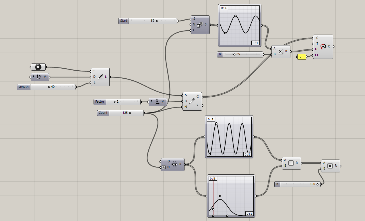
- Plug that Multiplication component into both a Remap Numbers component and a Bounds component (which then goes into the Source input of the Remap component. Create a domain with the Construct Domain component. Plug a slider into the A and B inputs, making the A input an expression. Plug that Construct Domain component into the Target input of the Remap Numbers component.
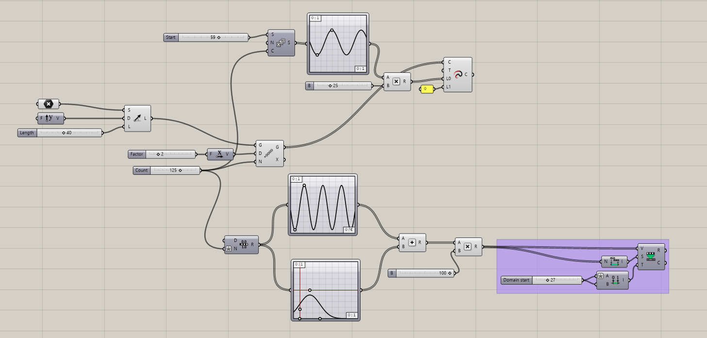
- To create the vertical movement, make a Rotate 3D component. Plug the Extend Curves into the Geometry input, and the Remap Numbers into the Angle input (making sure to change it to degrees). To make the center of rotation at one end, create a Point on Curve slider and make sure it is all the way at 1.000. The Linear Array component should be the input into that slider before it plugs into the Center input of the Rotate 3D component. Plug in a Unit X into the Axis input to control the direction.
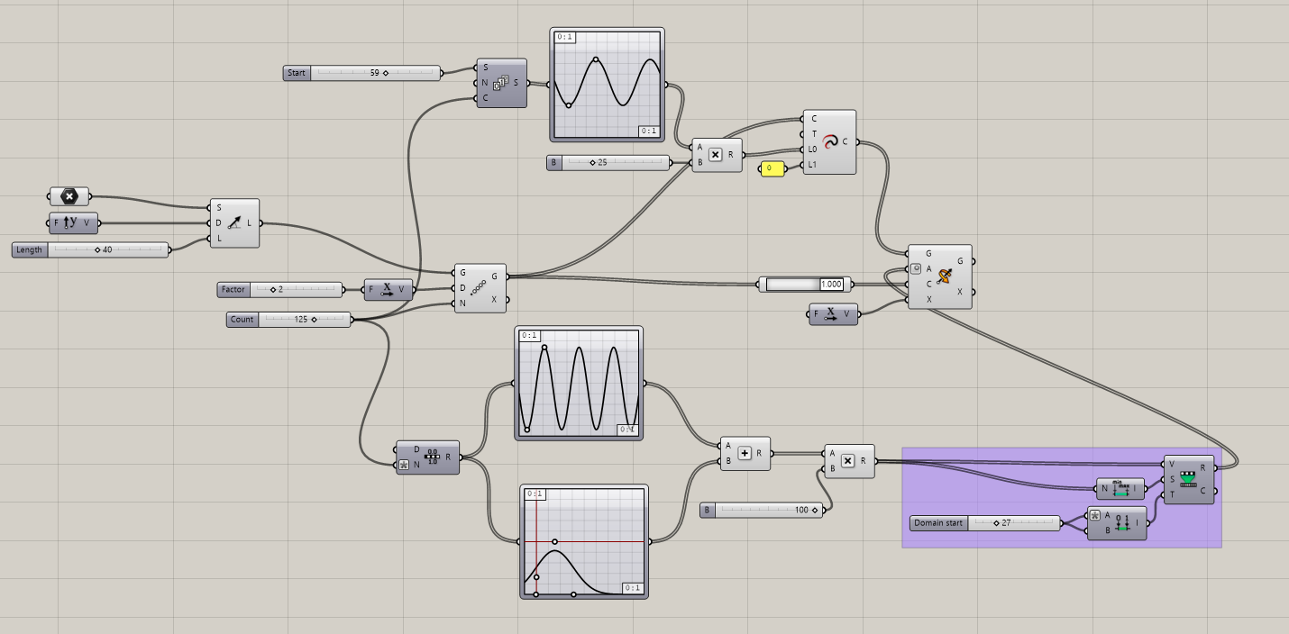
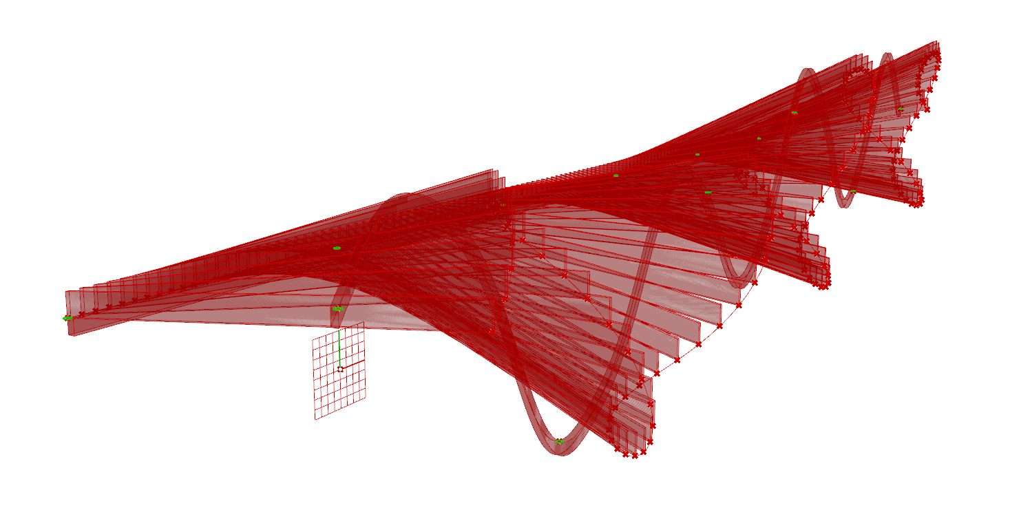
- To extrude the lines, plug the Rotate 3D into an Extrude component. Plug a slider into a Unit Z component into the Direction input of the Extrude component. To extrude the other direction, plug that into another Extrude component and then a slider plugged into Unit X into the Direction input. At this point you can hide the previews of all the lines from the previous steps.
Creating the Support Structure
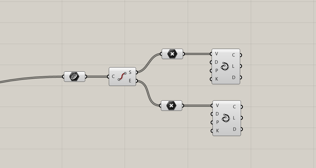
- Take the Rotate 3D component and plug it into a Curve component. To get the endpoints, plug that curve into an End Points component.
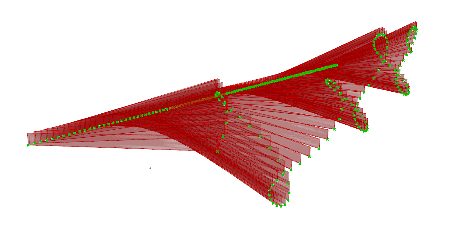
- To make curves at either end, you’ll have to interpolate these points. For each output of the End Points component, plug them into a Points component. Then plug each Point component into their own Interpolate component.
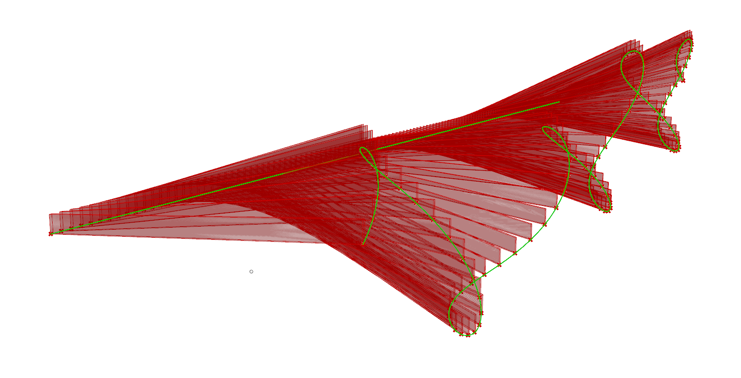
- The ‘End” end points will be the straight beam at the center of rotation. Take the Interpolate component from the End points and extrude them using the same method as the other beams. The only difference is making sure to extrude it in the Z and Y direction.
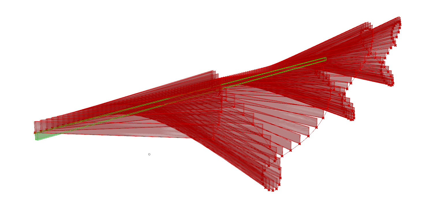
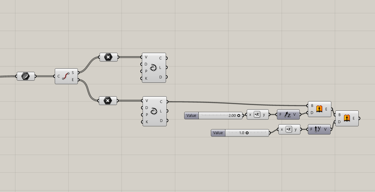
- The “Start” points will be the curvy beam. Plug that Interpolate Curve into a Project component. Then create a Point Component by assigning it to the original point you made. Plug that point into an XZ Plane component and then into the Plane input of the Project component. Plug that Projection into a Move component and then a slider plugged into Unit Y into the Motion input. This way this beam can be offset from the end of the beams. Finally, plug the Move component into another set of Extrusion components to extrude them.

- Create a Weave component. Plug the End Extrusion into the 1 input and the Curvy Start Extrusion into the 0 input. There should be 2 supporting beams now.

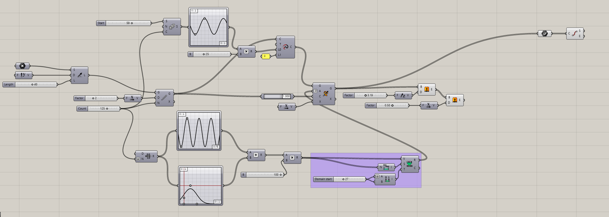
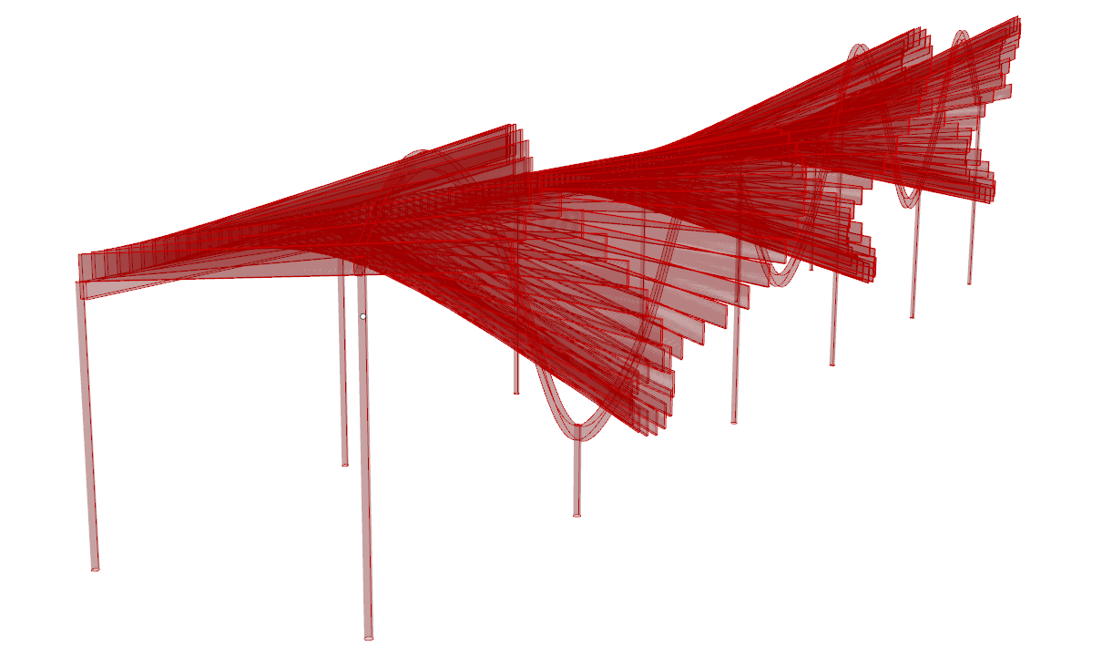
- To make the columns, start by creating a Divide Curve component. Plug the End Interpolate and the Move component into the same Curve input. Plug a slider into the Number input to control the number of columns under each beam. Plug the Divide Curve into a Circle component with a Radius slider to control the size of the circle. It is important to Graft the output of this component.

- Plug the Circle into a Project component. Plug an XY Plane into that Project component. Plug both the Circle and Project components into a Merge component and then into a Curve component. Lastly, use a Loft component to loft each circle to its projection. You should be able to hide any of the previous curve and points now.

Using OpenNest for Plywood Sheet
- Plug the wood beam extrusion into a Curve component. Project them to a plane by plugging that curve into a Project component along with a YZ component. Then plug that into a Rotate component. Plug an XZ Plane into the Plane input so that the beams are “flat” on the horizontal X Plane.
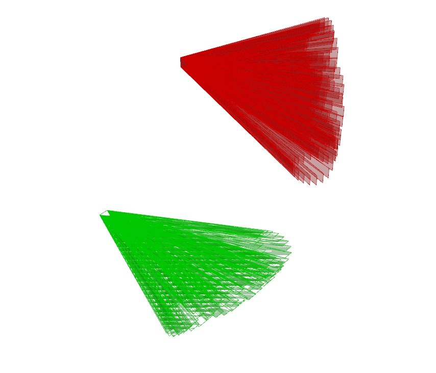

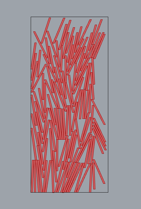
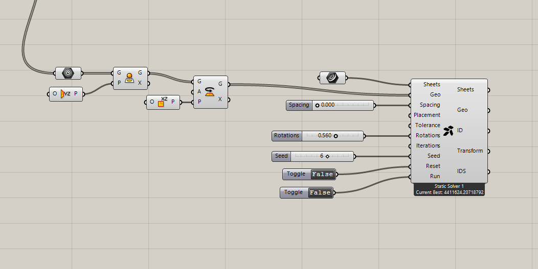
- To nest these beams onto a sheet, plug the Rotate component into the Geometry input of the OpenNest component (link to download is above). In Rhino draw a rectangle that will be the sheet, assign a curve to it, then plug that into the Sheet input. To make the nesting most efficient, make a slider for the Spacing input and make sure it is 0.0. You can also add a slider to the Rotation input and adjust it so that the beams are flat together. A slider into the Seed input can control different orientations of how the beams can lay on the sheet. You could also plug in Toggle components into Reset and Run to run different layouts.
Tips
- You can use different graph types, but I find it works best with Sine graphs.
- It is possible to change the circle shape of the columns with something else if desired. Just replace the Circle component with another component to create the geometry.
- Depending on how your beams are oriented, you might have to include Negative components when making extrusions to control the direction of the extrusion.
- If all beams don’t fit on one sheet, OpenNest should create another sheet of the same size until all beams can fit.
- If you want to apply realistic color to the beams, add a Custom Preview component along with a Swatch component to the end of each of the wood beam extrusions, Weave component, and Loft component.
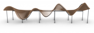
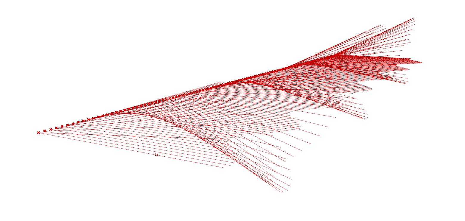
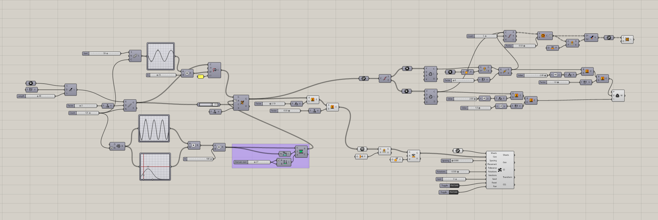
Final Script
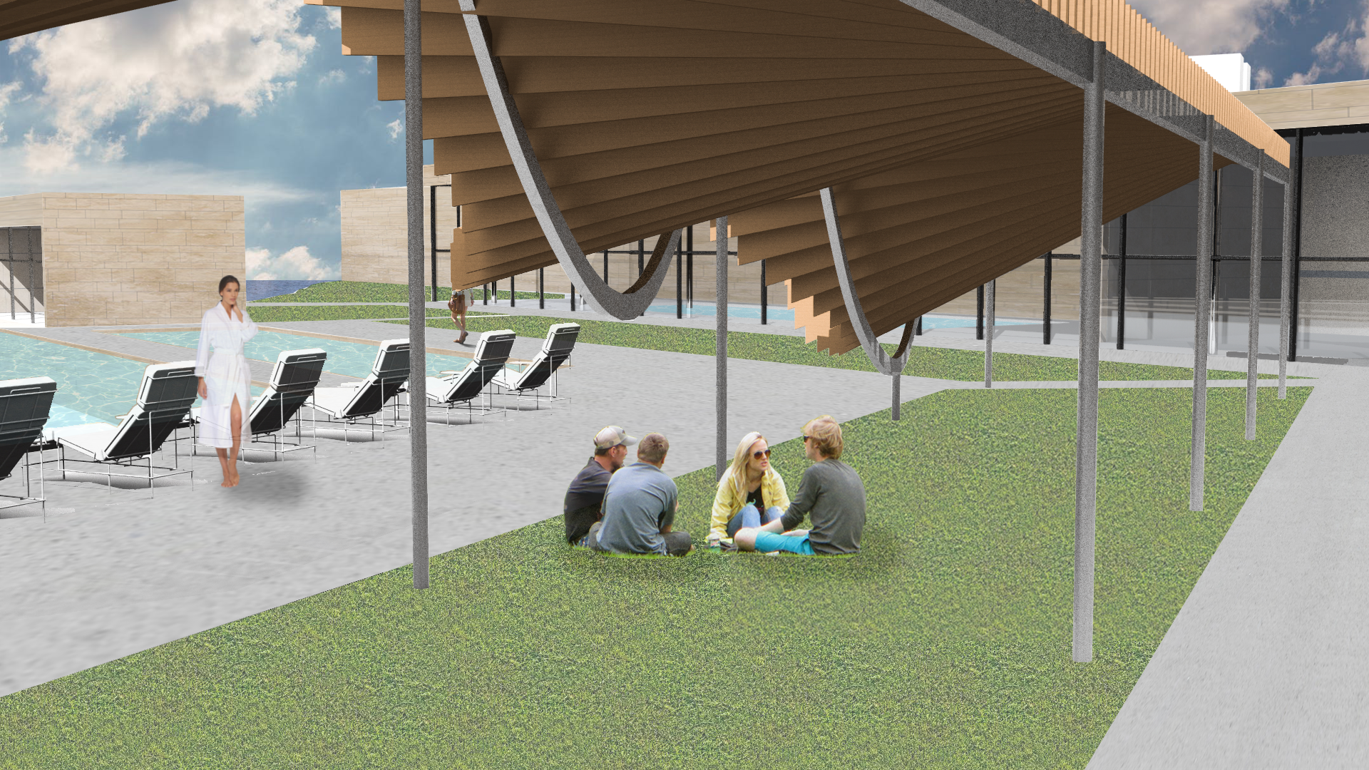
 I used my final canopy model as a canopy in an urban garden and spa for my studio project: