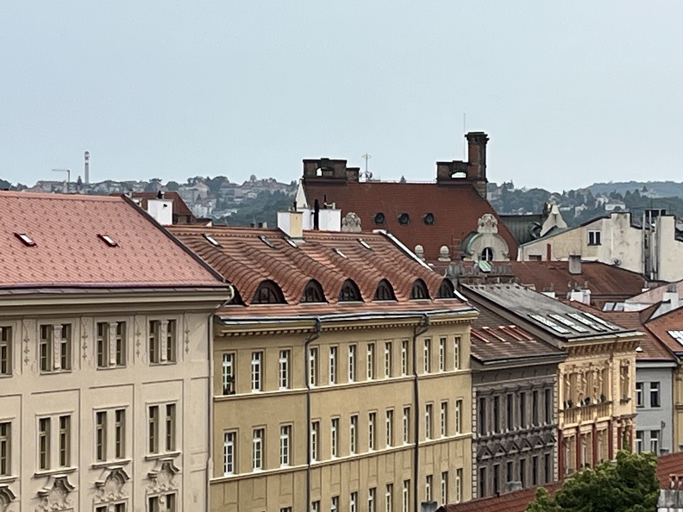
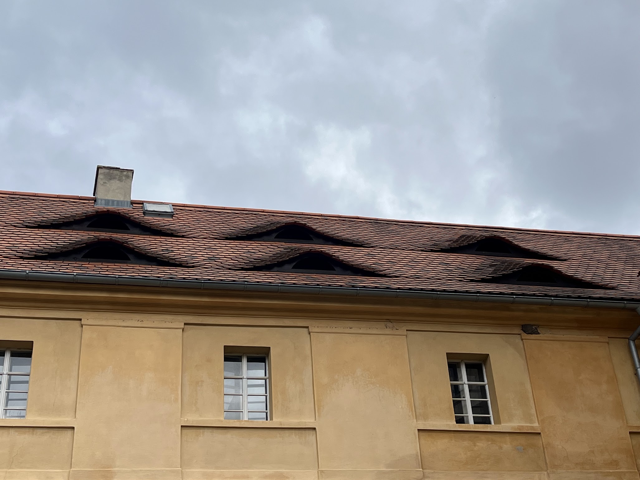
In my project, I was inspired by a certain kind of roof design here in the Czech Republic, where the tiles of the roofs had sort of moon-shaped holes for windows or ventilation. I was intrigued by that shape and design so I wanted to use that as inspiration for my tutorial.
I have used grasshopper as a tool to explore how the number of roof tiles can be optimized for building roofs that include integrated window openings. The goal is then to investigate how the geometry of the roof and the size of the openings affect the total number of tiles needed, while maintaining design flexibility.
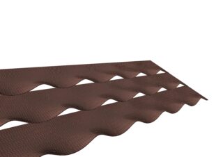
Here is an example of how the tiles often look, one side is pointy and the other has a cut, so that they could be attatch to each other, but still be flexible to the desired shape.
The script in Grasshopper
- Use the rectangle component to create a rectangular plane.
- Then adjust the size with the number sliders, this will define the ground of the roof, which later will become the module for the roof.
- Then by adding the surface component, the plane becomes a surface
- The radians and XZ plane component is added to get the right angle of the rotation of the plane. This is where you can decide the incline of the roof.
In this first part, you’re defining one part of the tilted roof, by creating a rectangle and angle it.


- The component contour creates contours of the surface in even steps. This divides the surface in sections, which is useful to extract levels or structure. Contour is one of many ways to do this step, but it is good if you already know your dimensions of the roof.
- Then add the component list item. The purpose is to get a specific curve of the surface that you can work with, for example control the placement, height, shape etc.


- Then by adding the component construct domain, you can define between which span you want your values, for exemple height or width. This is to be able to modify the points later.
- The component remap number takes one list of values and resizes it to a new span to be in control of the incline of the roof, or the height where you want the windows to be.
- Then add bounds to get the min and max value from the list. It is used as a “source domain” for remap numbers.
- To divide each point in X, Y and Z, add the component deconstruct point. Z is used to analyze the incline of the roof or the variation in height.
- To get the points where you can place the roof tiles or the windows, you can use the component divide curve. It will divide the curve in equal segments, which will give you your points along the curve.
This part of the script is to create controlling placement points on the roof, control the height and shape on the roof tiles and windows, and make the design flexible.


- To modify the height of the curves, you can add Graph mapper. It works as a tool to influence the height profile of the roof. By changing the graph, you’re able to control how much the roof is bending, and you will be able to choose the function that works best for you. It takes a number and gives you a new one based on the function you choose Then add the components Unit Z and Multiplication. Here, height vectors in the Z direction are created based on the result from the graph. The multiplication determines how much each point should be raised. Then add move. The points on the basic curve are moved vertically according to the height vectors. The result is that the roof’s edge line has a varying height profile.
- Then add Nurbs Curve. Finally, the points are connected with a smooth, continuous curve that represents a profile for the roof.
This step defines the overall shape of the chosen curve. By adjusting the graph, the user can control the roof height variations and create dynamic rooflines.


- Add the component Replace Items. Here, you’re replacing the chosen curve from the contours with the modified to later loft them together. It is used to update the roof profile.
- Then add loft. The Loft component generates a surface by connecting multiple curves. The result is the entire surface of the roof with slope and variation, based on the curves created earlier. Here we can see the importance of contour, since loft depends on how many curves it has.
- The next component is Transpose surface. It reverses the U and V direction of the surface. This is important to correctly divide the surface into a grid, depending on how the panels will be oriented.
- Then add the component Staggered Quad Panels. This divides the surface into rectangular panels (quads). Here you determine the number of panels in length and width. This is the basis for creating roof tiles that can be extruded or modified later.
In this step, the generated roof surface is divided into rectangular panels, which allows the definition of tiles on the roof. The number of panels and their shape can be easily adjusted, making this moment central to the ability to experiment.


- Next step is to add the component panel frame. This will create an inner panel within each roof tile, resulting in a frame with an opening in the middle. The scale factor determines how large the opening will be in relation to the entire panel.
- Then add extrude. The inner panels are extruded in the Z direction, giving them a certain height. This can be used to create depth in the openings, or to lift certain parts of the plates. Then add the component Unit Z. It determines the height of the extrusion.
In this step, you’re creating the panels of the roof.


- The next component is brep. This is the result of Extrude. Brep stands for Boundary Representation, which is a 3D object. This is the actual roof slab (or panel) that we can then process further.
- Then you add the component ArrCurve. It duplicates an object, in this case the roof module along a curve. It takes the geometry to be duplicated, the curve along which the object is placed, and the number of copies to be placed along the curve. Using this component, you can spread out the roof tiles along one or more curves.The Count slider controls how many tiles are generated, so you can experiment with the density and rhythm of the roof by changing the number of tiles in a row.
- Connect the component curve to ArrCurve. These are the curves used as guidelines for placing the tiles. The curves define the shape of the roof in plan and control where the tiles end up. By adjusting the shape of the curve, you can change the contour of the roof and therefore the overall geometry of the roof. I made my curves in rhino, but you could also do it parametric by using the edge curve of the first rectangle.
- Then add sliders. It you control over the number of instances (tiles) in each Array Curve. It lets you experiment with how many roof tiles to create along each curve. A higher value gives more and smaller tiles; a lower value gives fewer and larger tiles. This way you can study different variations of the roof’s expression.


Below are some different iterations, of how you can use the script to transform the design depending on your desires:


