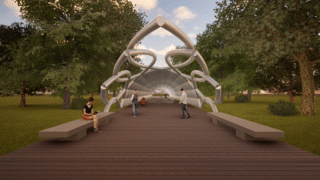
CONCEPT
The project is focused on parametric architecture and has as a reference the life tree of the Milan’s Expo 2015. At the end the model can be used as a tunnel or entrance for some public transportation building.
REFERENCES


TUTORIAL: this tutorial will follow a practical, manual and clear method of scripting, ideal for beginners and for who is going to learn Grasshopper plug-in for Rhino.
First step: spiral creation
At the beginning is importart to take in mind that grasshopper doesn’t have a specific and direct command for helixes and spirals so it’s necessary to build it working with points.


Start with “Point Cylindrical” and give it all the parameters you need for the construction of the spiral; for example, in this tutorial, the tunnel’s widht will be 5 meters so connect 2.5 to the radius and due to the fact I’m creating a tunnel and not a tower i need to put the base plan on YZ.


As you can see, connecting some parameters thank to “Range” and “Construct Domain” commands makes the points to follow a spiral geometry that can be modified by height, amount of points and the number of turns based on Pi (180°) where the points are distribuited along.


The “Interpolation” let the possibility to create a curve along all the points we created before and connecting the curve to the “Rotate” component we can rotate the same spiral with degrees (3.3 video).
Second step: parametric tunnel


For creating a normal parametric tunnel is enough to use “Merge” for connecting all the degrees to the “Radians” component to create a rotate copy of the spiral and mirror everything based on XZ plan at the end.
At the beginning and the end of the tunnel i wanted to create these such of nails distribuited as crowns on the entrances of the structure.


At this point is not enough simplifying everything with “Merge” but it’s possible to use “Range” or “Series” but this will be the next step of the scripting, let’s go on like that.


To give this tunnel a surface, to create something in 3D we need to connect to the geometry the component “Perp Frames” because give the possibility to create an amount of plans which are parallel to the spiral and placed where the points was at the beginning of this tutorial (2.1/2.2). Remember to give the amount of plans by connecting a number to counts.
Attention! Connecting “Perp Frames” to the geometry out of the “Mirror” component makes the plans follow just one direction and not the both mirrored so we need to disconnect “Mirror” and connect it after.


To make a surface based on a circle we need to connect to “Perp Frames” the specific component named “Cirle” (if you want to create a surface based on a square you will connect the component “Rectangle” or “Polygon” or whatever) and give it a dimension so a radius.
From this point to the end of this step the script is kinda easy and understandable.
Create a “Loft” to make the surface following the circles and connect it to the “Mirror” we had before (5.1/5.2). The component “Brep” give the possibility to close the sufaces and creare a closed 3D element but if you connect it to “Mirror”, you will have only the mirrored elements closed but if you “Merge” loft and mirror together to the “Brep” you will have the total work done in 3D keeping just a component showed on Rhinoceros.
Third step: entrances
For the nails that makes these tunnel’s entrances more interesting we need to separate each spiral when we merged all the rotated copies (4.1/4.3).

Go to the first component we created “Point Cylindrical” and copy all the script we did for each spiral you are going to work on (I’ll go each 30° steps)
Now we will try to move and replace just the last two points of a spiral to stretch it and create with the other spirals the nails.
Connecting “Point Cylindrical” to a “List Item” for every point we are going to move makes possible to set the point free and move it based on coordinates. From “List Item” connect the input “Index” to the number of point of the spiral we want to move (remember that we put a hundred points for the spirala t the beginning) so the last one, the number 100.
After setting the point number 100 free (100 -> List Item -> Move) we need to move it through the “Construct Point” and give it the coordinates x and z (not y, but if you want to try you’ll figure out why not y).

Use the same script for the point number 99.

Use “Replace Item” and connect the List to the output of “Point CYlindrical”.
Connect also the component “Move” to the input “Item”

Connect the number 100 and the number 99 to the input Indices because “Replace Item” have to know which point you want to replace.

Adding a “List Item” in the middle like in the picture is worthy for the amount of point of the spiral. That component give us the possibility to change the amount of points (1.1/2.1) and select always the last two points instead of just the number 100 and 99 (in this tutorial there will always be 100 points).

Connect “Replace Item” to the old script from “Interpolate” to “Rotate”.

Each of these scripts in the pictures number 7.x will be connected to “Merge” (Rotate -> Merge) because we need to move the last two points for each spiral rotated.


Connecting some coordinates makes the point move and as you can see, something happened, we stretched the points.


The same process for the opposite side (the picture show the spiral 0°/360°)
I can already tell you that the entrance that concerns the movement of points number 100 and 99 is made from the spirals with a rotation of 180°, 210°, 240°, 270°, 300°, 330° and 0°/360° and the entrance of the opposite side concerns the spirals with a rotation of 0°/360°, 30°, 60°, 90°, 120°, 150° and 180°.


Going on with the scripts number 7.x we will reach a satisfying result but you should find the right spirals from where to pick the points. For example you see on the picture that there is the longest nail on the top, that one comes from the spiral with a rotation of 270°


CONCLUSION
The tutorial ended with the pictures 9.x and I want to say again that this is a long process, there are easier ways to do this tunnel but noone of them satisfied me like this one which give practical and manual control of settings; make an example:


Starting with the same script but connecting the base plan at “Rotate Plan” make the initial spiral to be copied (in offset) every 30° for 12 times (so from 30 to 360) that avoid all the copy and paste we did in the other script.


And this is the result with curves.

With a script like that we can have much more overall control of the tunnel model thanks to the graph mapper there that let us create the “nails” we have at the entrances and the other components that have the same role of the ones we used to replace the points 100 and 99 in the other script.


Ending in this way makes the work done. The first picture with curves and the second for the 3D model.
ADDED POINT
As last thing I would like also to show a thing that can make this parametric tunnel more interesting.

This script makes the structure of the tunnel to get thicker in the centre and thiner on the entrances, but if we change the type or we move the “Graph Mapper” we can see what happens in the video.