
For my final project in CAD Grasshopper I have decided to modify an organic logo into a rectangle-like structure.
CONCEPT:
Before I started, I have made a concept draft depicting potential steps to be made in the process.
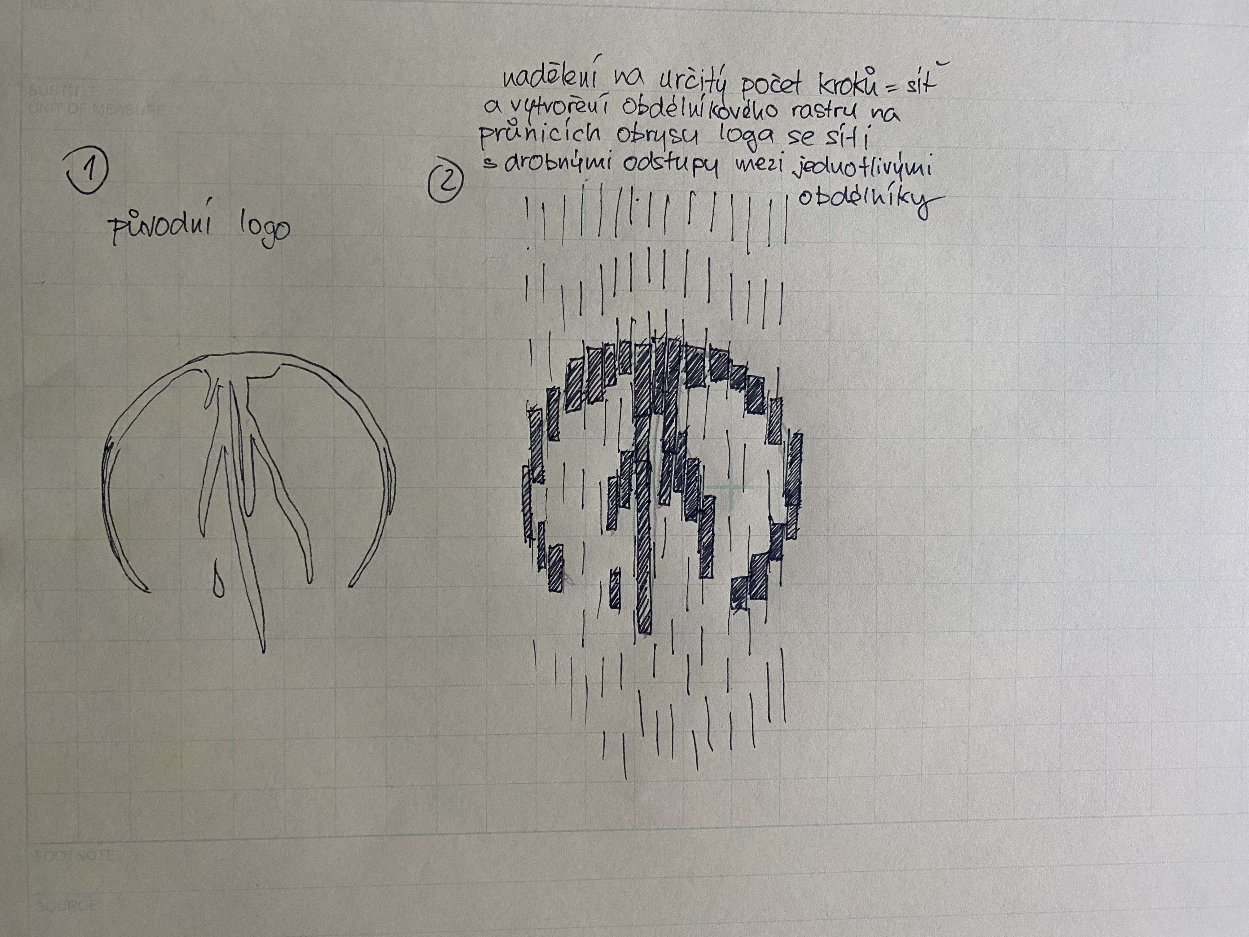
1) The original logo
2) The logo is divided into rectangle segments by vertical lines
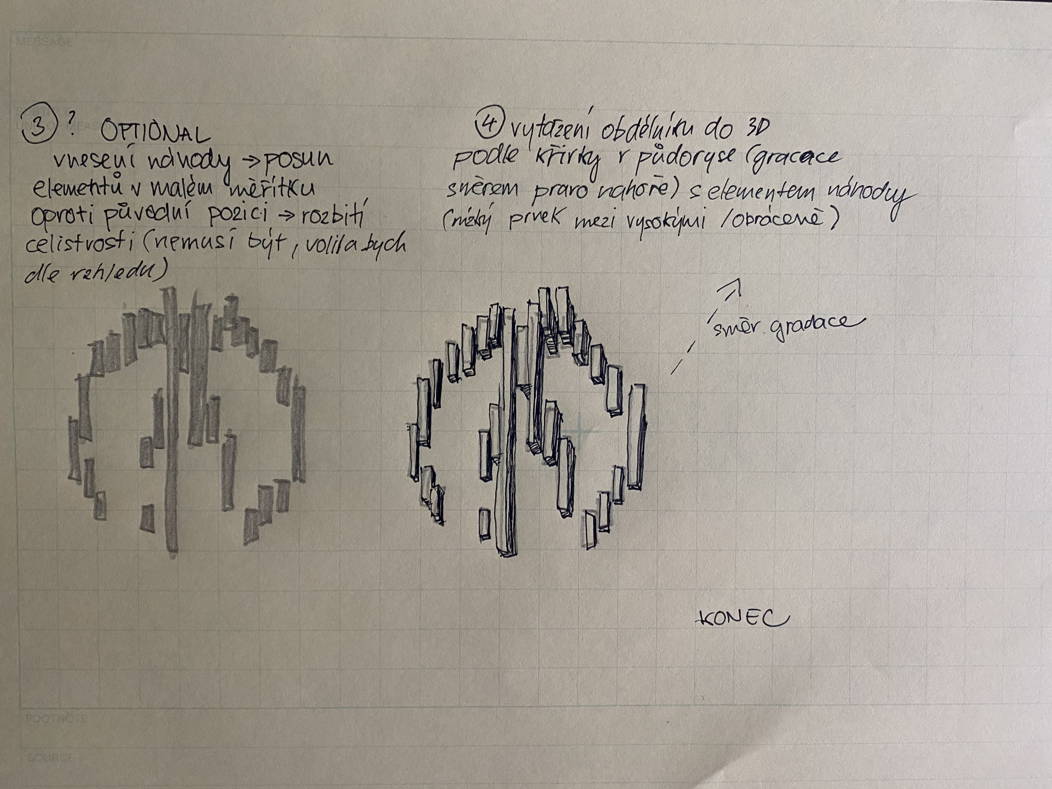
3) The individual rectangles are randomly slightly moved along the Y axis to disrupt the circular shape of the original logo
4) A third dimension is created by extruding the segments in a given direction
SOLUTION:
STEP 1 – Importing the logo in vector curves into Rhino 6 and setting it in Grasshopper


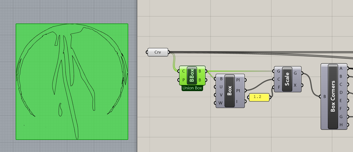
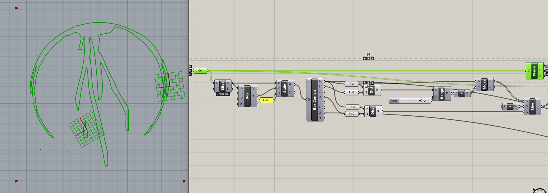
STEP 2 – Creating a vertical grid
– We use “Bounding Box” on the curve, which we have to set to union. Otherwise we would have two boxes for each closed curve.
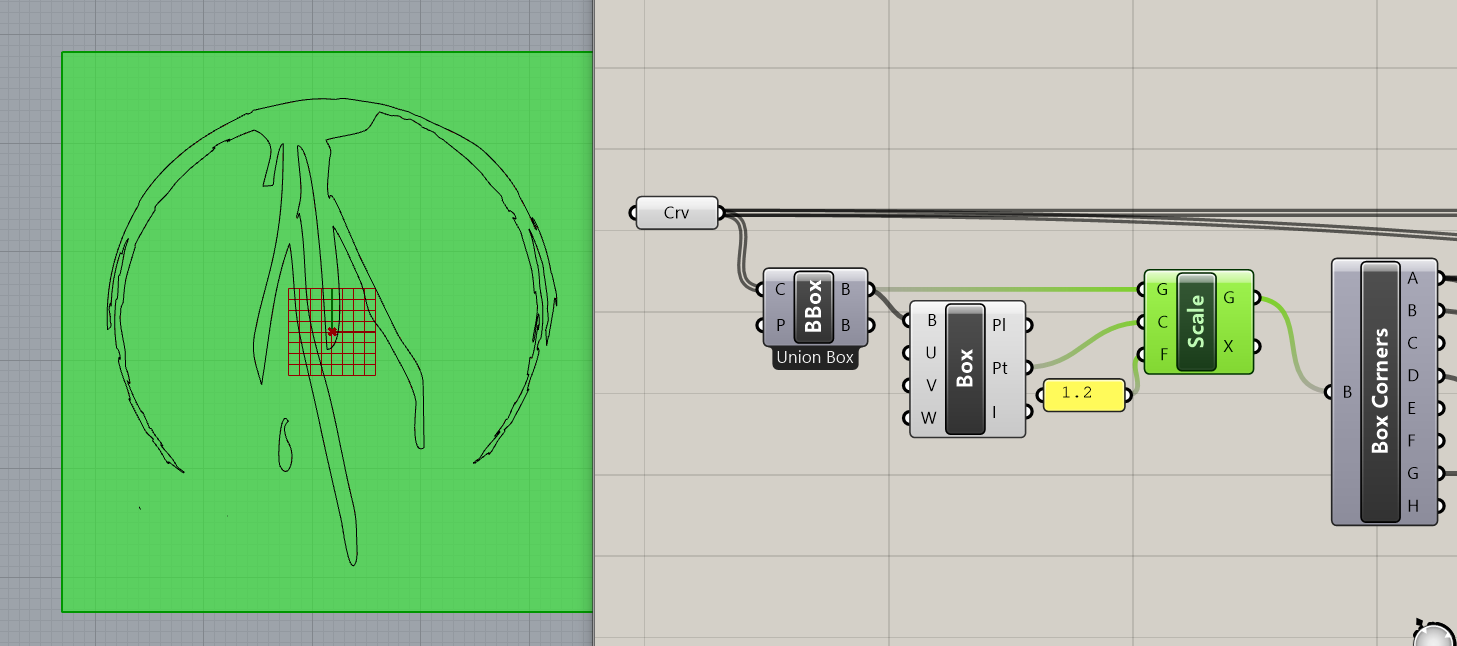
– On the box, we use “Evaluate Box” and use the center point to scale it by factor 1.2. This gives us a little bit more room for vertical lines.
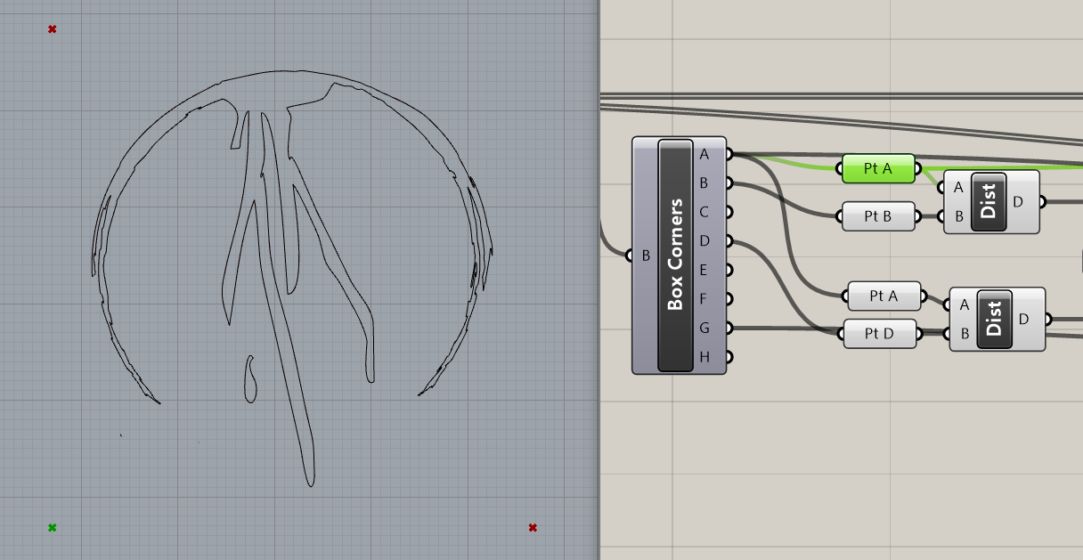
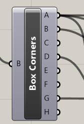
– The lines will be created from the distances of corner points which we get from “Box corners”.
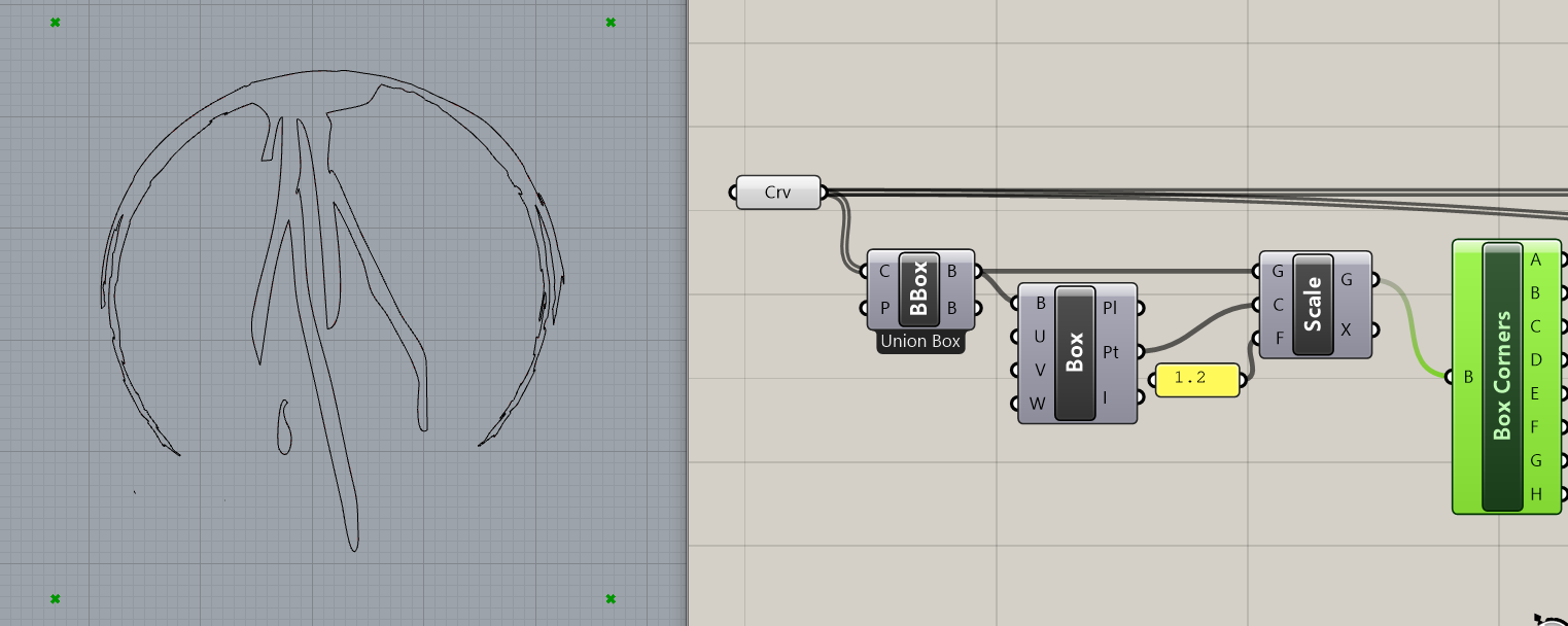
– By this function we extract box corner points A,B and D and measure the distance between A and B, A and D.
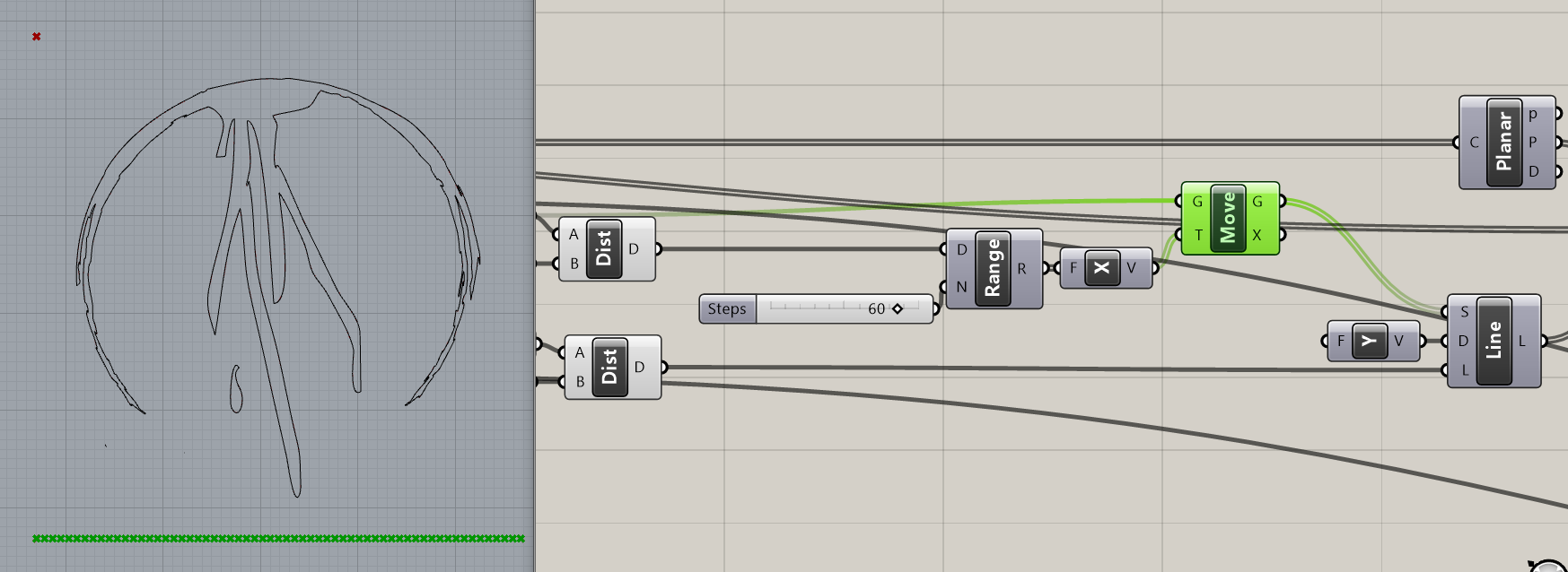
– Since we want vertical lines we first use the distance between points A and B and Range it into required number of steps (equals number of lines), in my case 60, which we feed into Unit X vector and move the point A along it. This gives us 60 starting points for vertical lines.
– From those points we create vertical lines by function “Line SDL”, direction is “Unit Y” vector and length of the lines is the measured distance between points A and D.
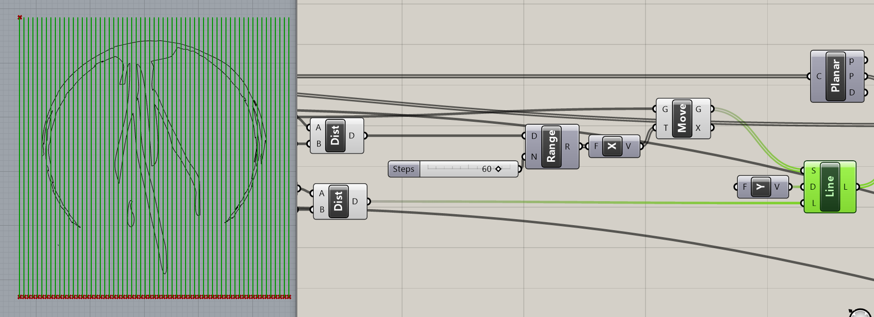
– We now test planarity of the logo curves.
– And use “Trim with regions” function in which ‘curves to trim’ are our vertical lines, ‘regions to trim against’ are logo curves and ‘plane’ is given from “Planar” function. Those split curves inside of the regions are future rectangles’ axis.
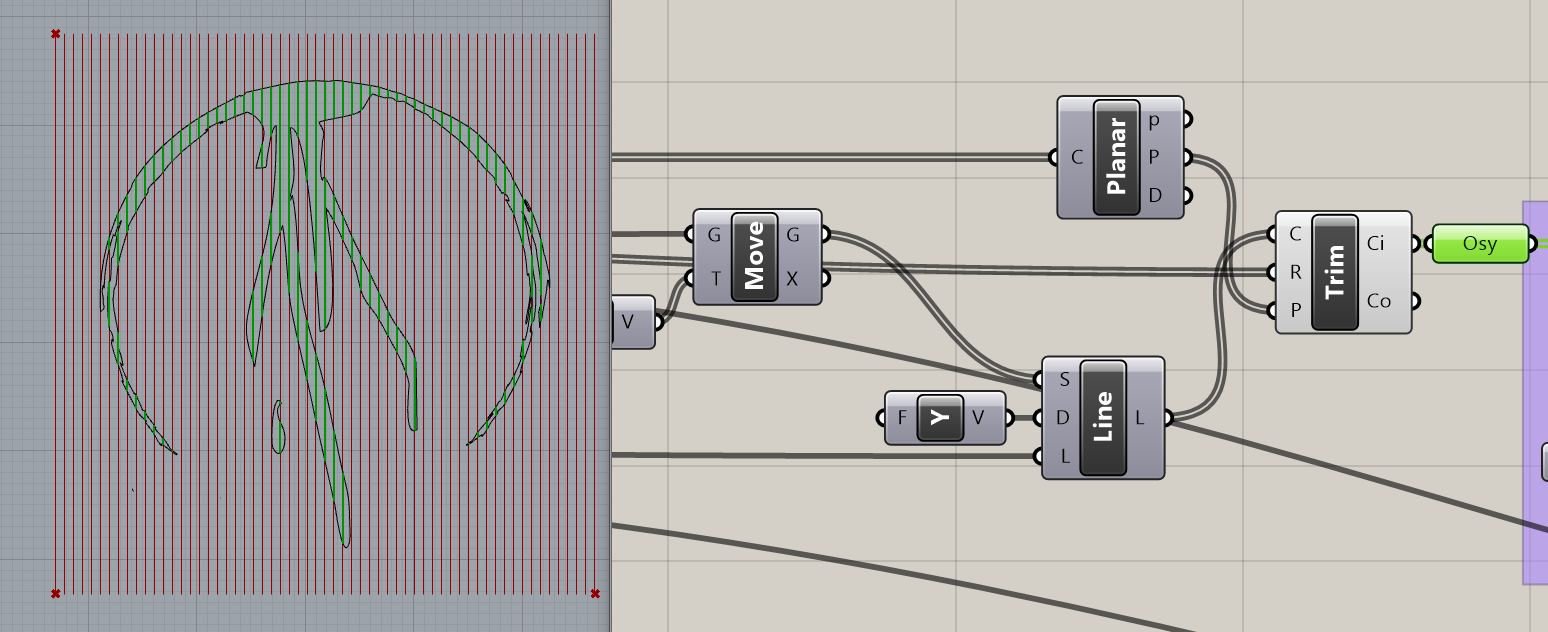
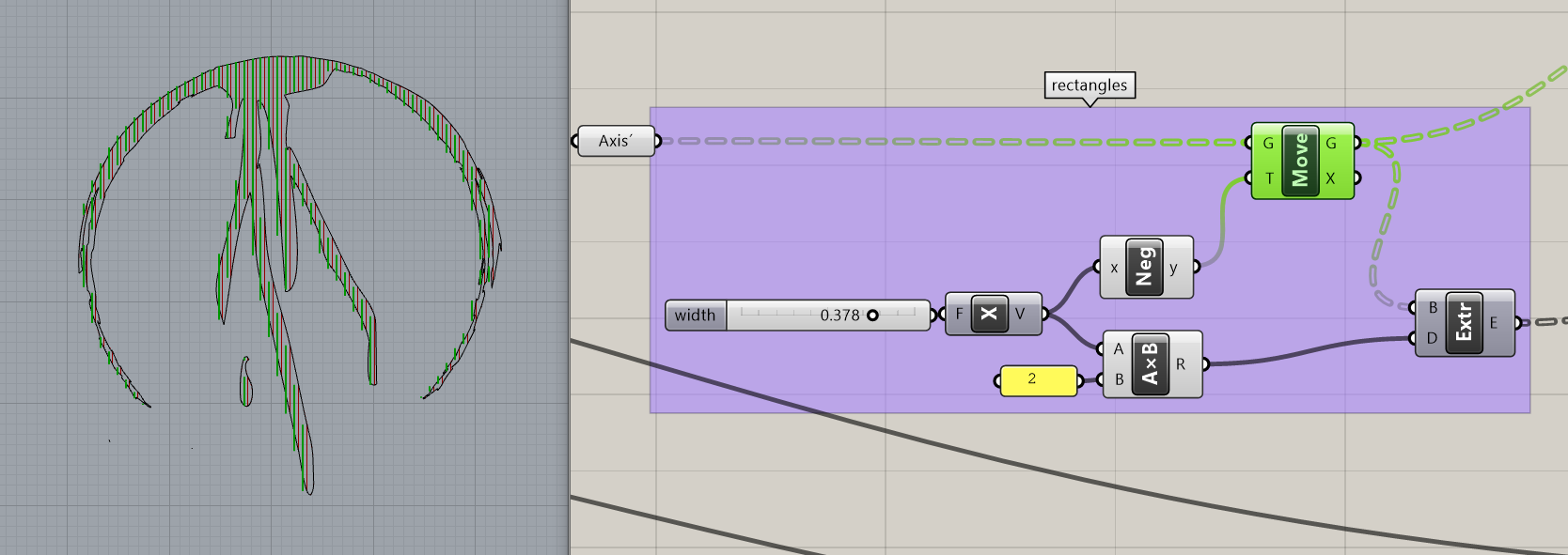
– To create rectangles from axis we will use “Extrude” but since extrusion only works in one direction (left or right) we first move those axis along Unit X vector to create left sides of the future rectangles.
– The vector of movement and width of the rectangles are dependent, the numeric value on the slider is used for movement along X-axis in negative as well as for creating the width of rectangles by multiplying the same numeric value *2 in positive.

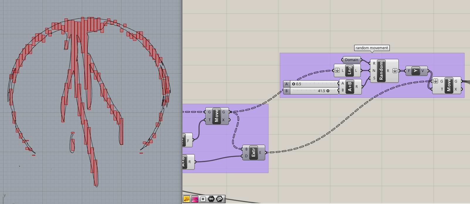
STEP 3 – Random movement of individual rectangles
– We create “Random” list of numbers, domain of numbers is set from -1 to 1, the number of random values is s number of axis´ movements, which is 106. For seed I used two added sliders. This gives us 106 values ranging from -1 to 1 for each rectangle. We feed those numbers into “Unit Y” vector and move the extruded rectangles with it.
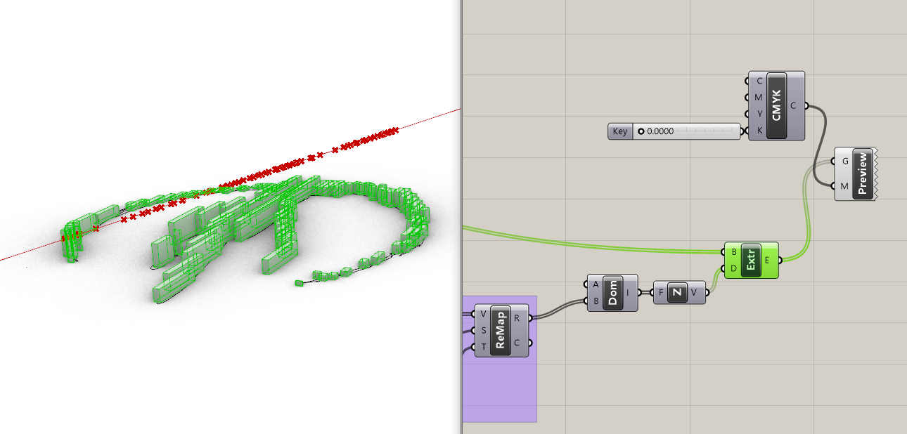
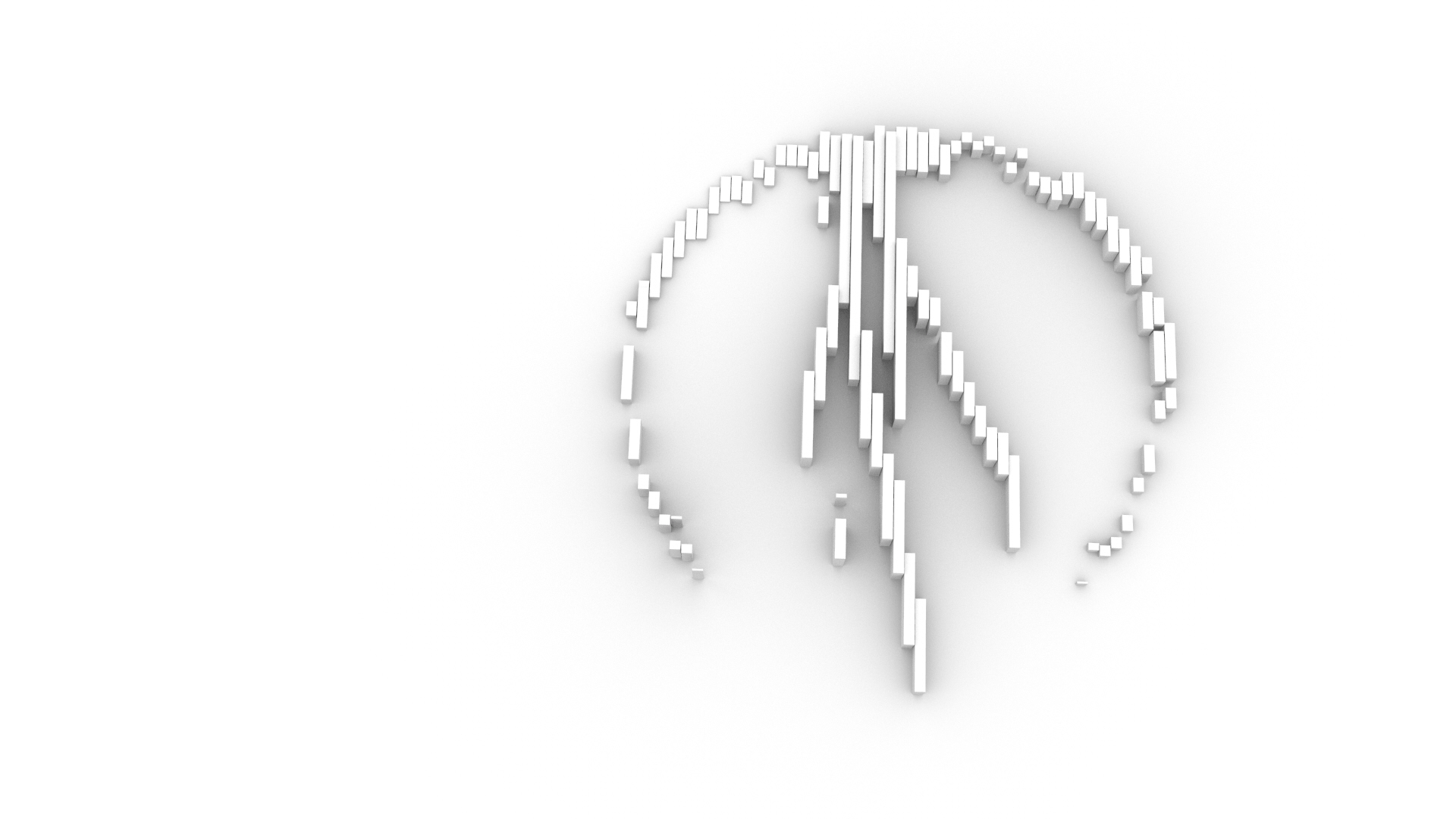
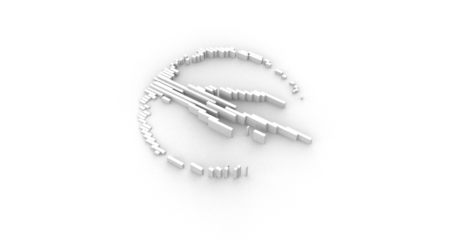
STEP 4 -3D
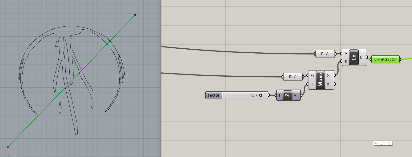
– First we define an attractor curve. I wanted to disrupt the original logo’s circularity even more so I used a diagonal line. The line is defined by “Box Corners” used in STEP 2. I chose point A and point G which I lifted along “Unit Z” vector by a value set on numeric slider.
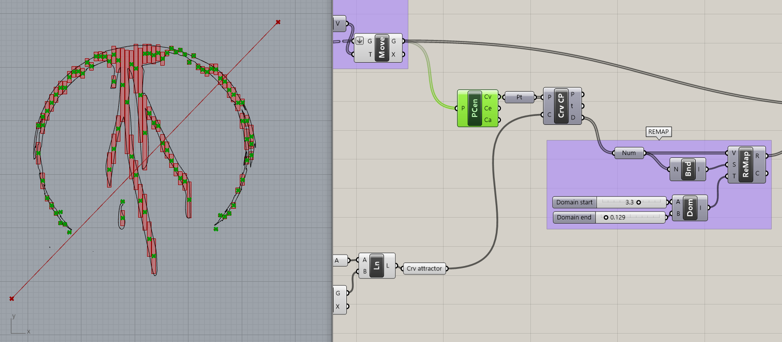
– Now we use “Polygon Center” to find center points of the rectangles. Those are fed into “Curve Closest Points” which calculates the shortest distances between the points and the attractor curve. These numbers will be used to create height of the rectangles. The rectangles which are the closest to the attractor line will be the highest.
– Numeric sliders connected into “Construct Domain” represent the lowest and highest levels of rectangular prisms. Then we REMAP those numbers into new numeric domain.
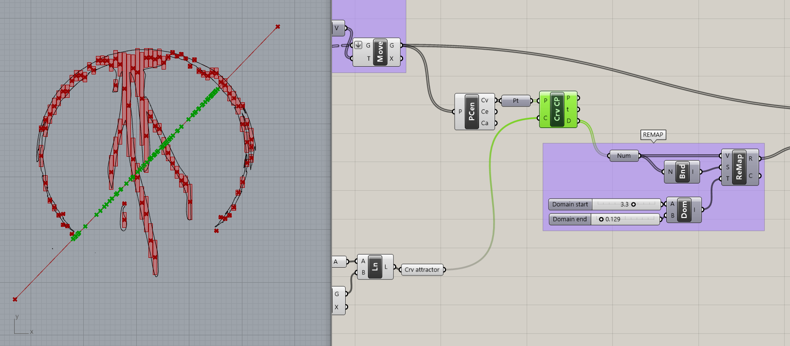
– And finally the remapped numbers are connected into a domain which is fed into “Unit Z” vector which is used as a direction for extrusion of the rectangles. Lastly, “Preview” function is used only for demanded color of the result.
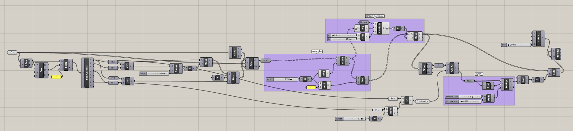
– Whole script:
Files for download: