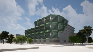
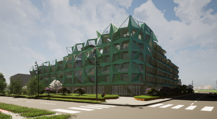
This tutorial shows a step by step instruction on creating an ornamental facade for a residential building. The design is a play on traditional Latvian ornaments, but makes them geometric to preserve functionality. The structural part of the extrusions create framing that surrounds balconies and enclosed spaces with either vertical studs or glass. A facade has been parametrized to create different extrusion lengths to maximise the amount of sunlight that the facade is able to capture.
Step 1
– creating the base surfaces
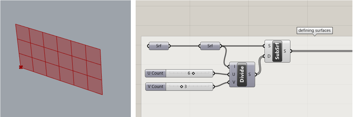
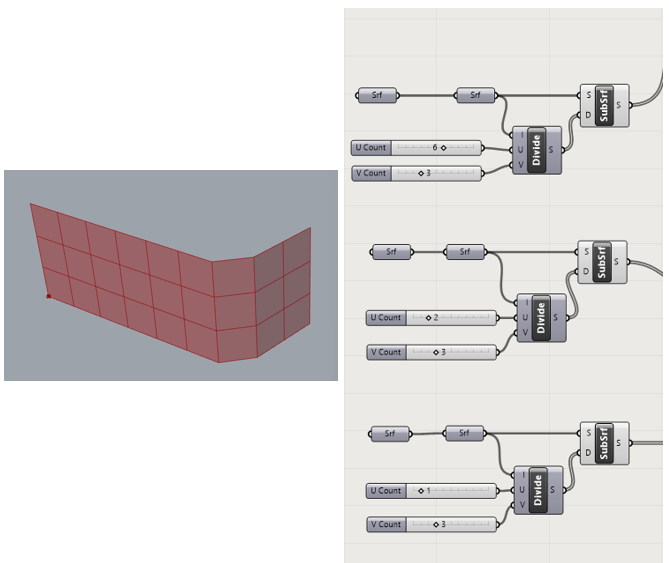
The first step is defining surfaces of desired size in rhino and setting them in grasshopper and then dividing into equal segments, which are later connected into one subsurface.
Since the desired facade has three faces, the same process is done for all three.
Step 2
– defining the necessary parts of surfaces to be kept
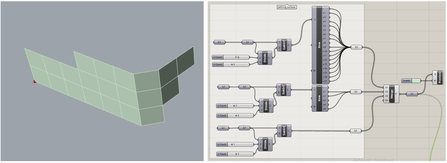
The next step is removing unnecessary parts of the surfaces or in this case, defining which ones should be kept. To do this, for two of the surface’s component item is used and the desired parts are connected into one surface, which are later also merged into the full facade base.
Step 3
– creating pick pints for each square and picking their vertices
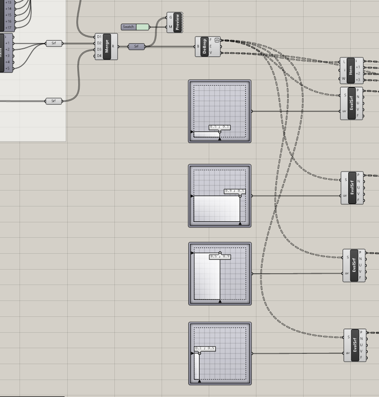
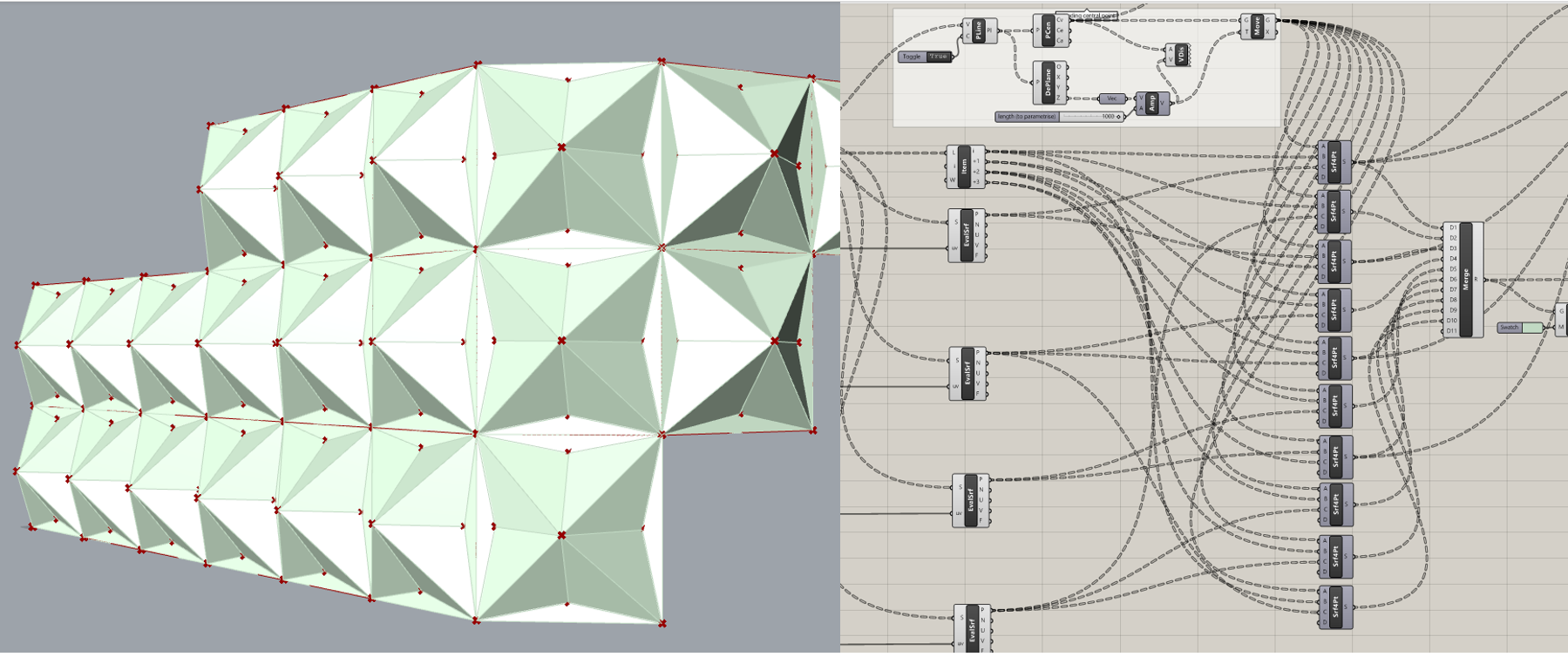
To create the desired shape, it is necessary to define pick points for each individual square. With deconstruct brep and item the vertices are being defined, and MD slider defines the local «coordinates» for points on the surfaces which is extracted through Evaluate surface.
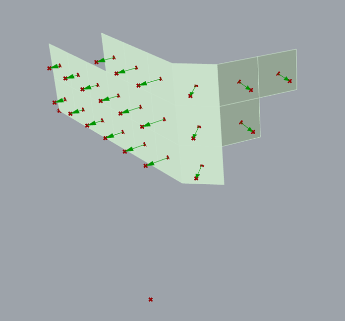
Step 4
– finding and extruding centre points
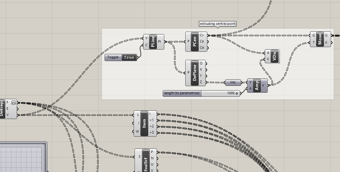
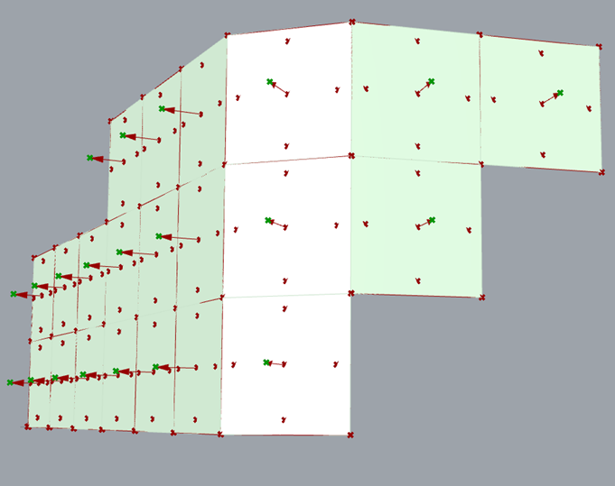
To extrude the centre points, they need to be defined, but since Grasshopper only has a component Polygon centre said polygon is first created as a Polyline from square vertices. Deconstruct plane is used to find the direction in which the points will be moved, and it is the z axis vector of the planes.
For now, the vectors Amplitude is set to 1000 mm, but this is the value that will later be parametrized.
Step 5
– creating surfaces through each necessary three points
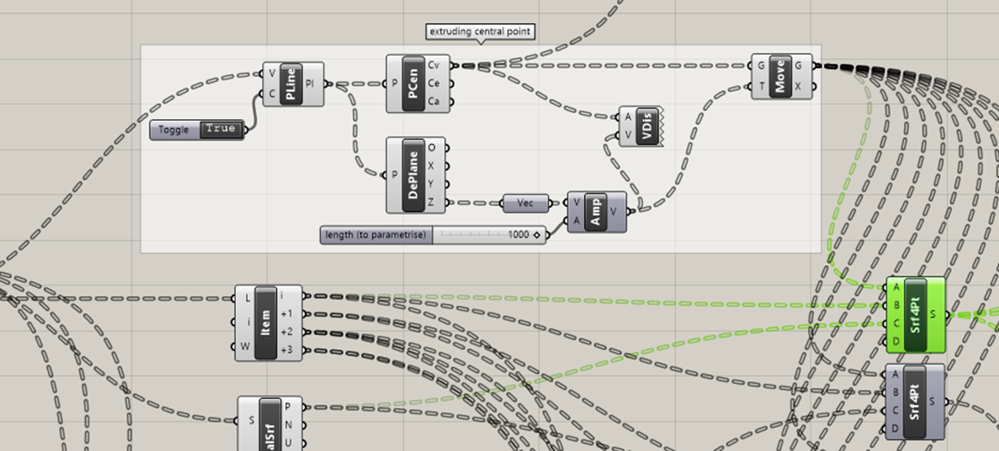
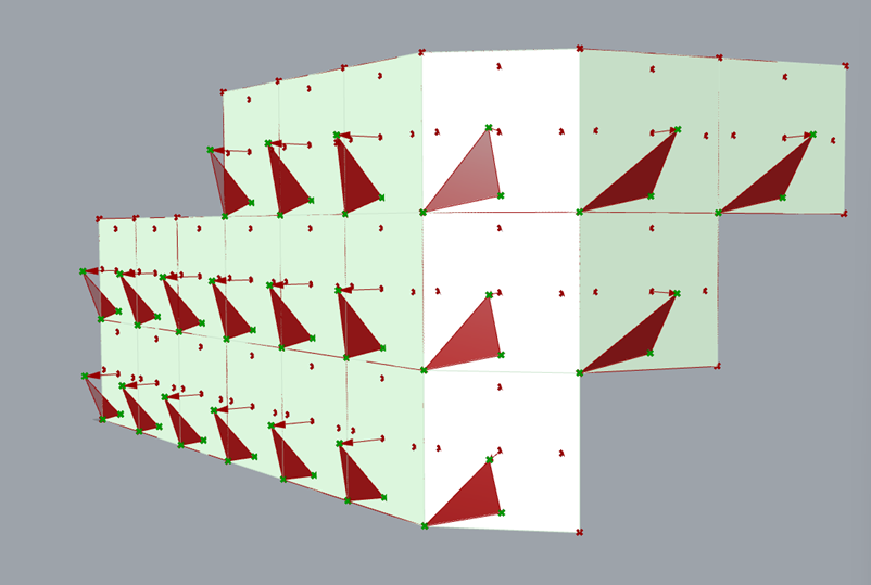
Now it is possible to create the shape itself. The façade elements are triangular with all vertices already defined, which allows the use of 4-point Surface component. The image shows one of the elements as an example.
With the same principle 7 more triangular planes are created, later merging them in one surface/Brep.
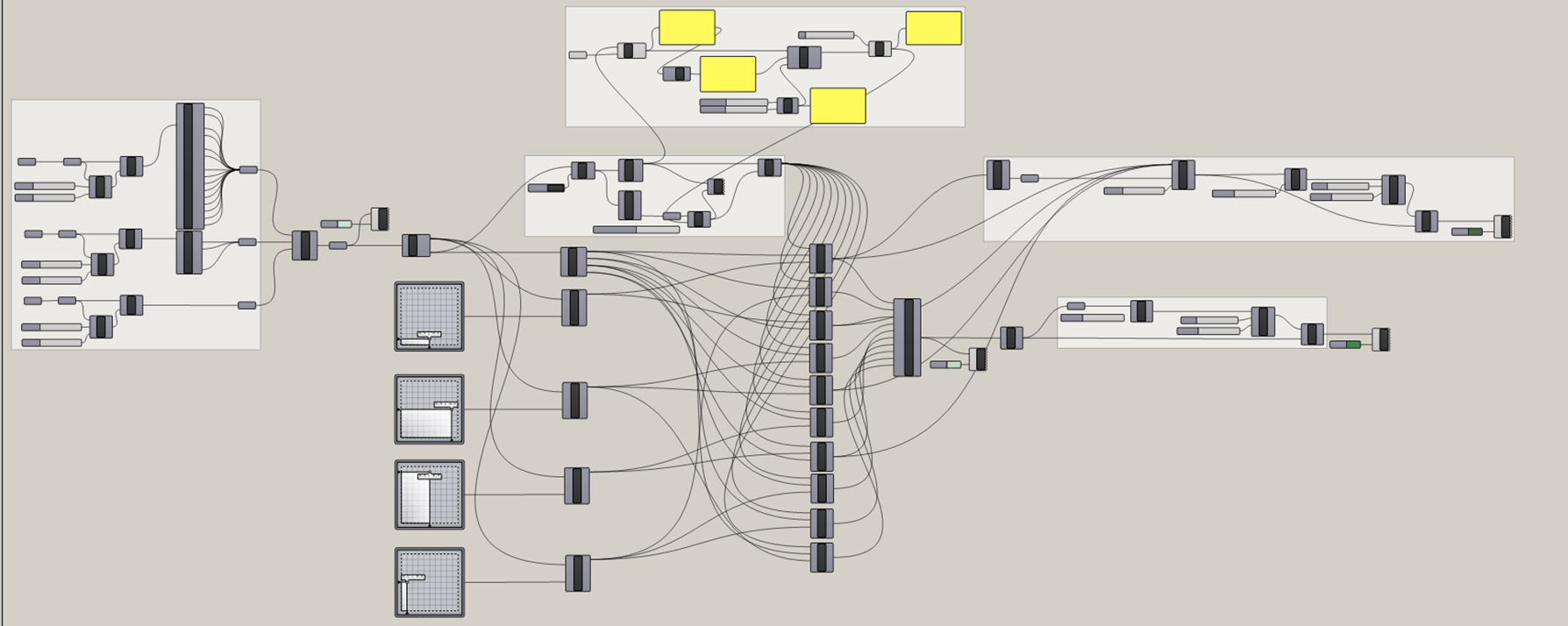
Step 6
– creating framing
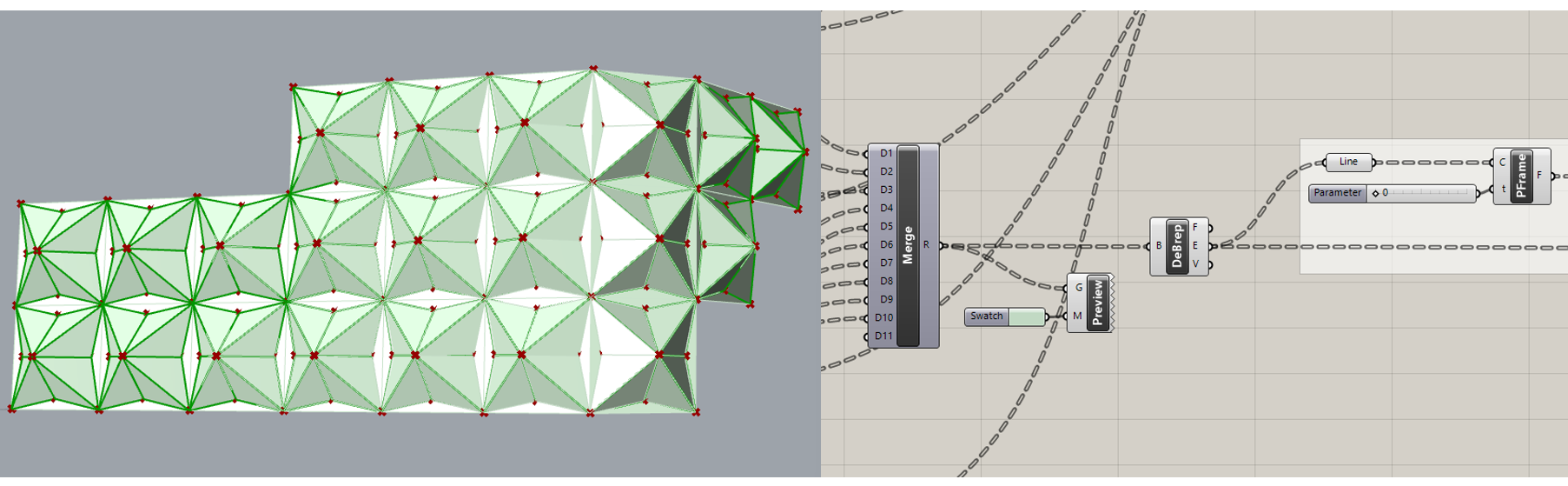
In the facade the triangular planes are either glass curtain wall elements or openings with vertical studs. For both variations a structural support in a form of framing is necessary.
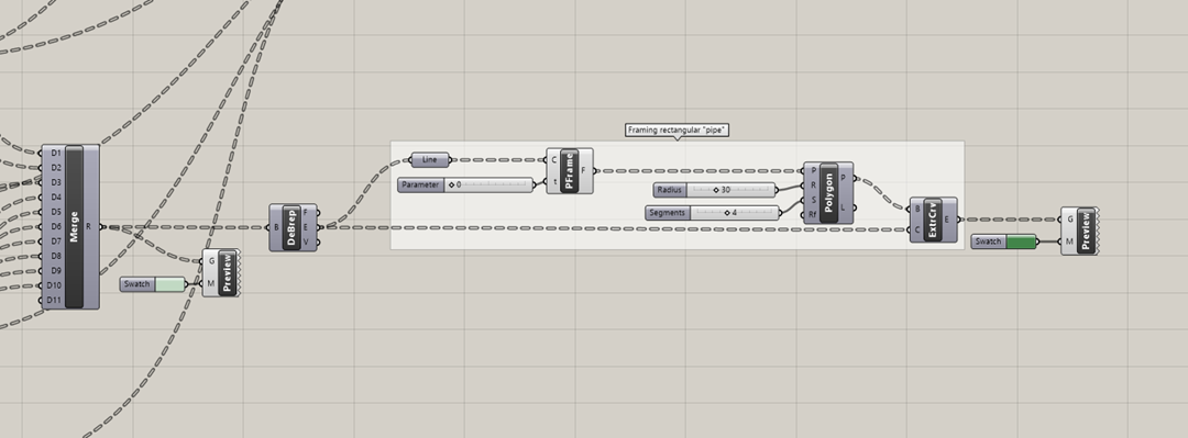
To create it each line that will be a part of the framing is defined and on its one end is added a frame perpendicular to the line.
The plane is used as a base for a Polygon with 4 edges that is then extruded along the curves that are the base lines.
Step 7
– creating vertical studs
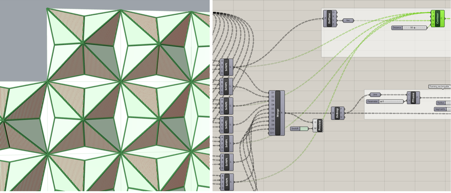
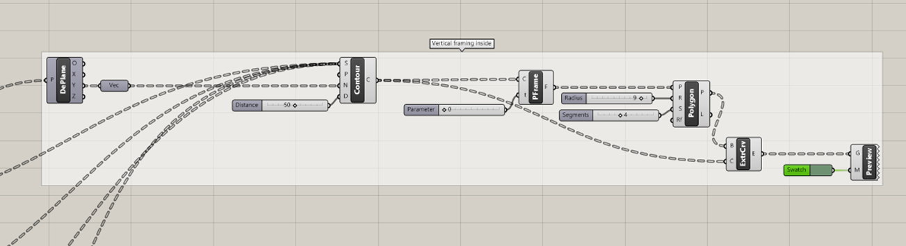
The studs are used in open balconies in the facade to act as railing. To create those the base surfaces are Deconstructed to extract Y axis and along it a series of contour lines are being created with 50 mm distance in between. The Contour is applied to all the necessary surfaces within the pattern, in this case to 4 of those.
Next the resulting lines are used as a base for perpendicular frames and extruded rectangles in an algorithm similar to that of the 6th step.
Step 8
– parametrising the offset
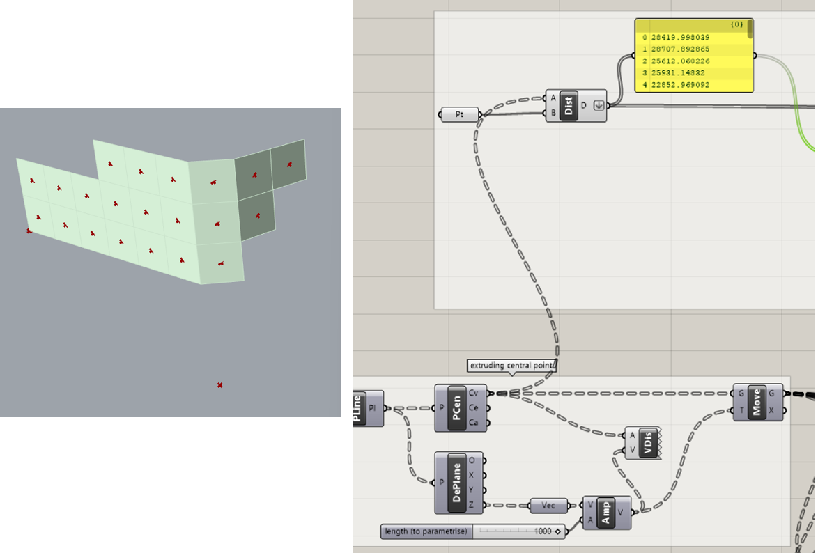
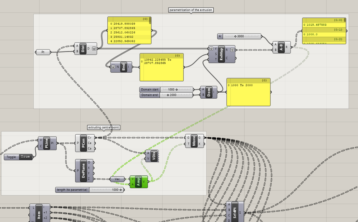
To make the facade more responsive to its surroundings (collecting as much light as possible in the given circumstances) the centre point extrusion is being parametrized. The goal is to make extrusions longer towards the corner.
An attractor point is being defined perpendicular to the corner plane. From there it is necessary to calculate the distance between the point and centre points of all squares.
Now the distances are being ran through the Bonds component to determine current maximal and minimal values (distances), This data is added to the component ReMap as the base numbers and reference distances and the component Domain suggests The new values should be from 1000 to 2000 mm.
To invert the results, meaning to make the extrusion that is the farthest from the attractor point the smallest, Subtraction is being used.
Now, the new set of values in plugged into vector Amplitude instead of one defined value of 1000 mm like the 4th step suggested.
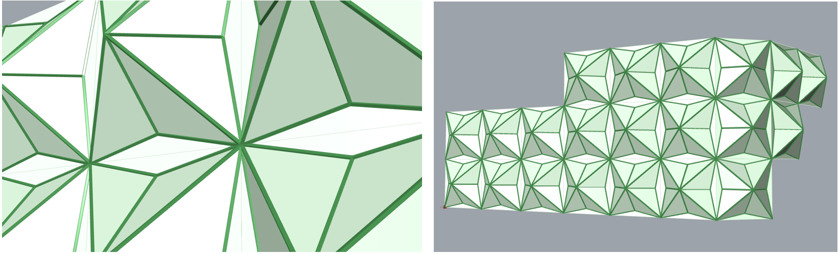
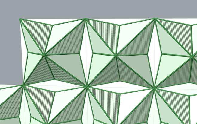
Finish and feedback
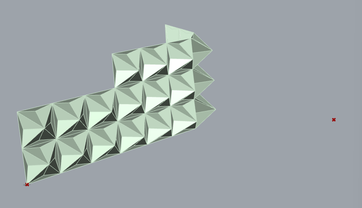
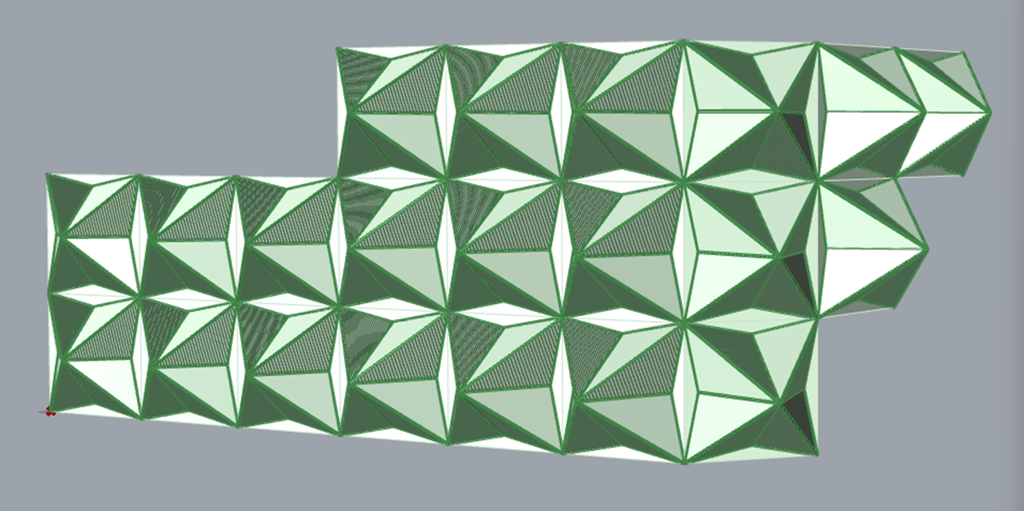
Enabling all previously for the convenience disabled elements. The new extrusion values change the previously created shapes. The facade element is ready to be added to any other 3d modelling software or to be rendered.
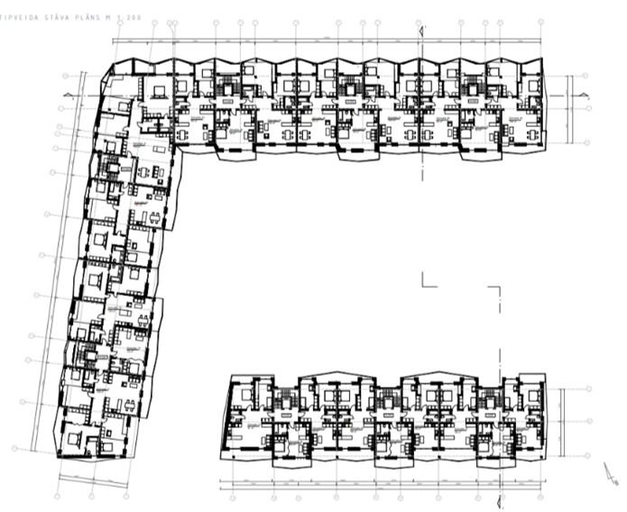
To improve the design even further it would be possible to try separating elements and customising them for different purposes that correspond to the floor plans and their intended purposes.
What is more, the parametrization can be done with the LadyBug plugin if necessary and when the intended facade is more affected by direct sunlight.