Grasshopper file:
Aim
The objective of this project was to develop a fully parametric timber tower using Grasshopper, creating a workflow that integrates geometric design, structural generation and digital fabrication within a single definition.
The design is inspired by the Pyramidenkogel Tower in Austria, whose expressive twisting geometry is recreated through parametric relationships rather than manual modelling. Instead of producing a fixed shape, the Grasshopper definition allows the tower to adapt dynamically by modifying a set of design parameters such as the number of floors, floor height, section radii, spiral displacement and torsion angle.
The project extends beyond the generation of the external form. Once the tower geometry is defined, the script automatically creates its structural system by generating vertical and horizontal beams, resolving their intersections through fabrication joints and preparing every structural element for laser cutting.
The final outcome is a complete digital workflow that transforms a parametric architectural concept into fabrication-ready components.
Project Result
Grasshopper Workflow

The Grasshopper definition is organised into four main stages:
- Generation of the parametric tower geometry.
- Creation of the structural timber framework.
- Fabrication preparation through joint generation and beam extraction.
- Automatic labeling and nesting of all components for laser cutting.
Stage 1 – Parametric Tower Generation
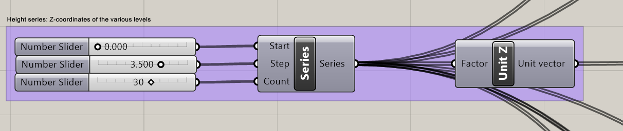
The tower geometry is generated from a series of horizontal elliptical sections distributed along the vertical axis. The number of floors and the floor-to-floor height define the overall scale of the tower, while a set of Graph Mapper components controls the evolution of the section dimensions and the overall silhouette.
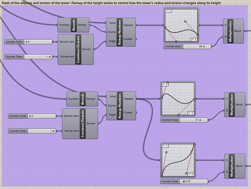
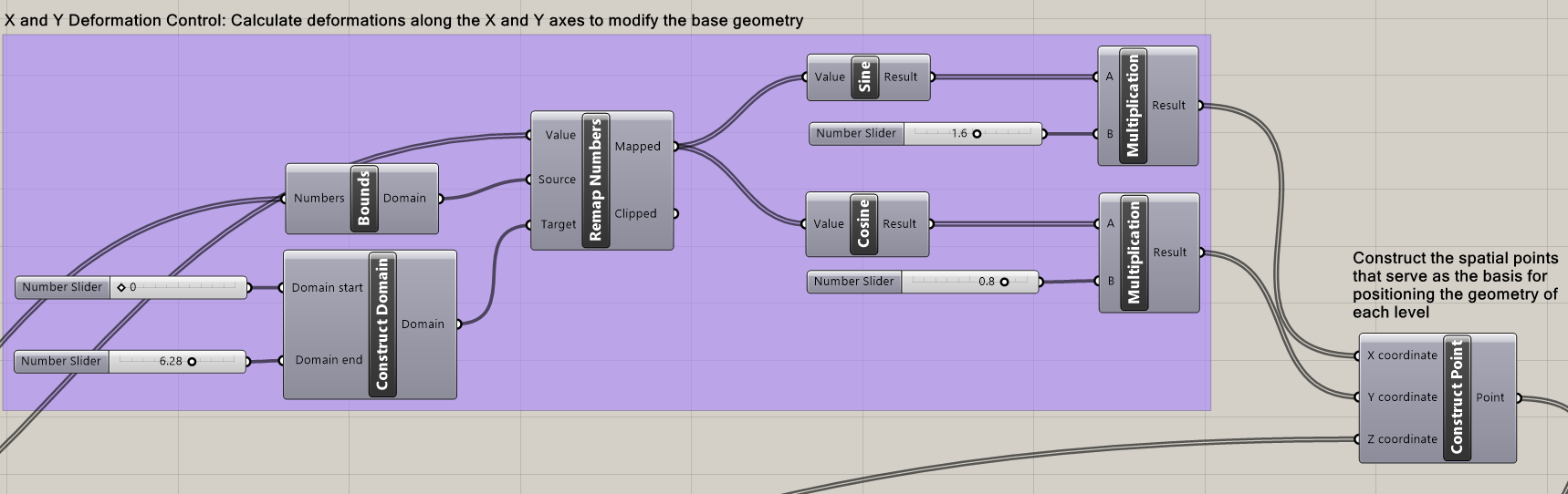
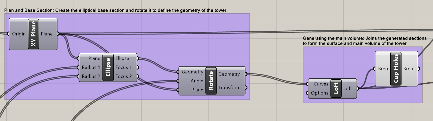
To avoid a purely vertical configuration, the centre of every floor is displaced using sine and cosine functions, producing a smooth spiral movement along the height of the tower. Each section is then progressively rotated according to a torsion function, generating the characteristic twisted form inspired by the reference project.
Finally, all rotated sections are lofted into a continuous surface, producing the parametric envelope that serves as the basis for the structural system.
Stage 2 – Structural Beam System
Once the tower surface has been generated, the structural framework is created automatically.
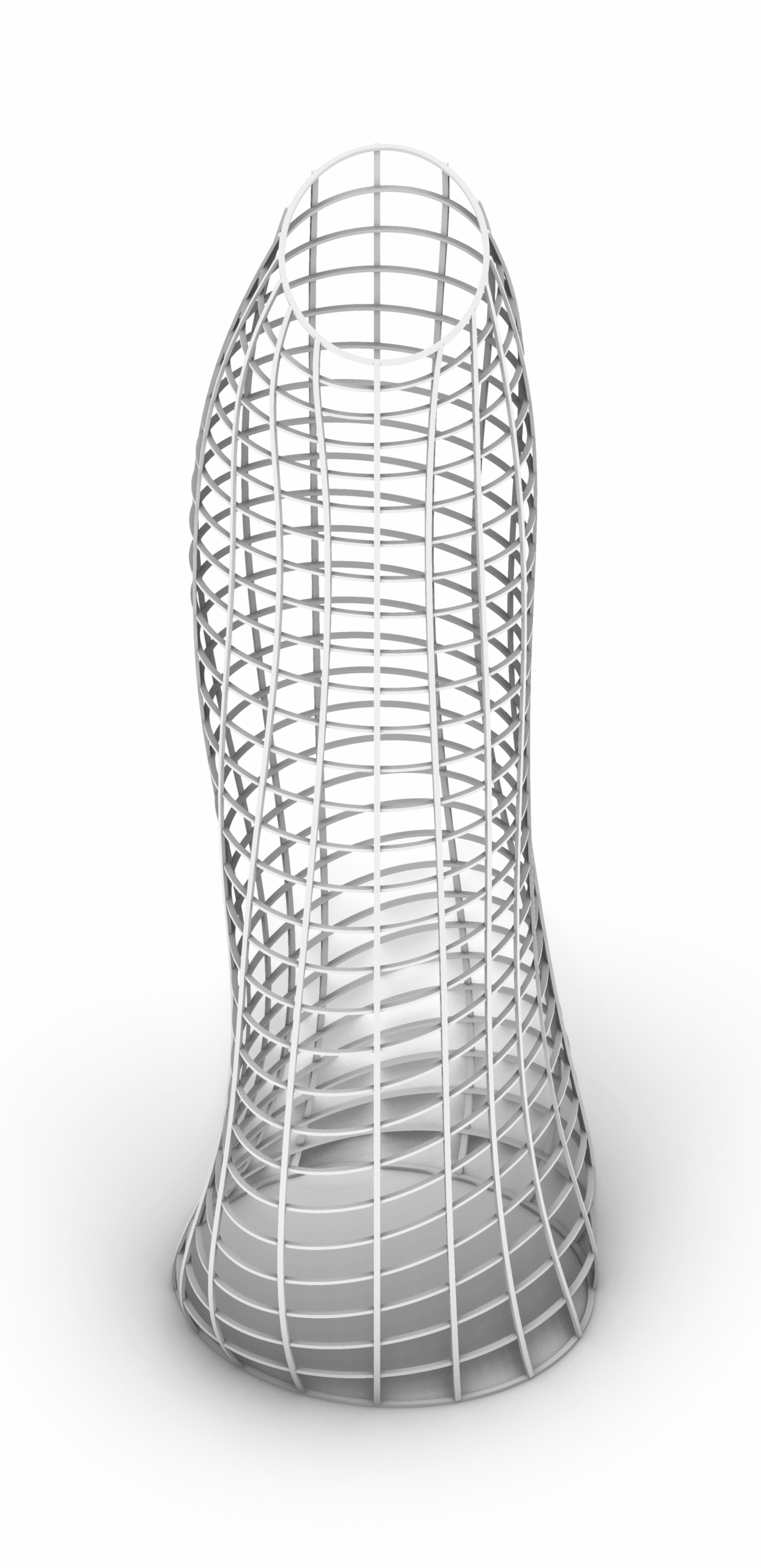
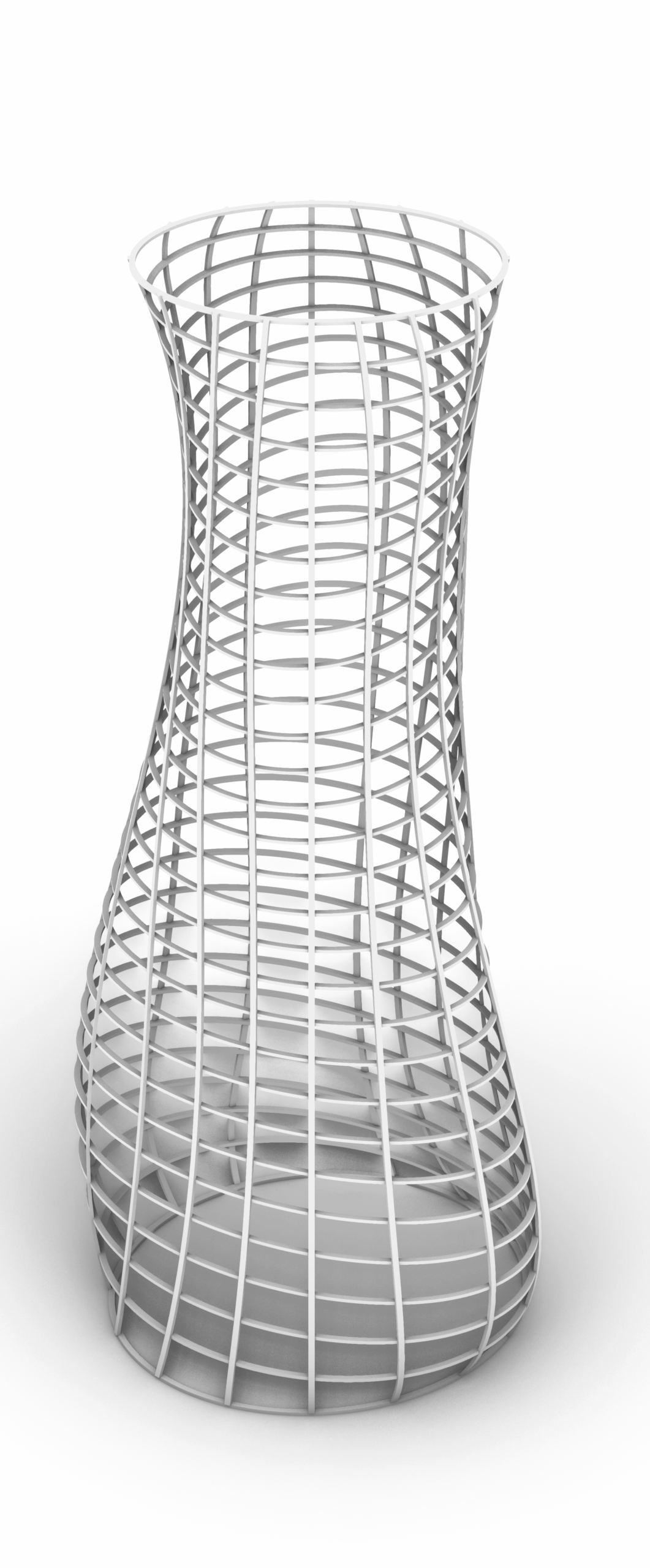
Sixteen vertical cutting planes intersect the tower surface to generate the curved vertical beams, while thirty horizontal planes produce the perimeter rings. Both systems are then transformed into structural members with adjustable rectangular cross-sections.
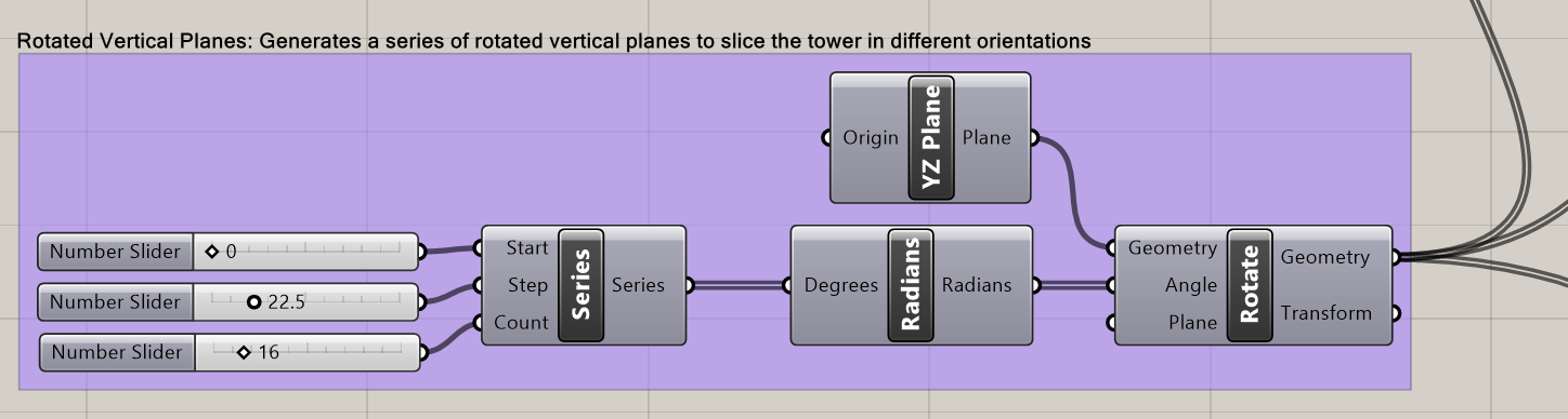
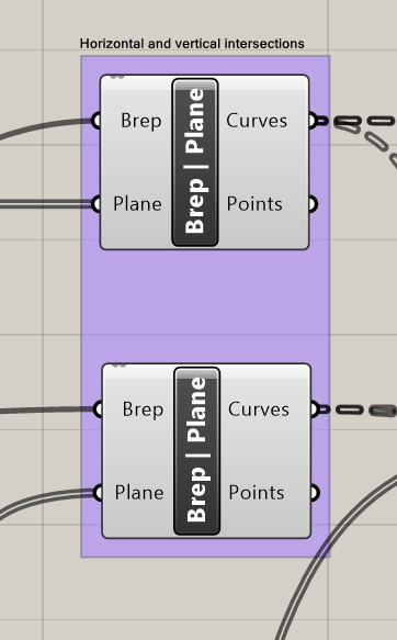
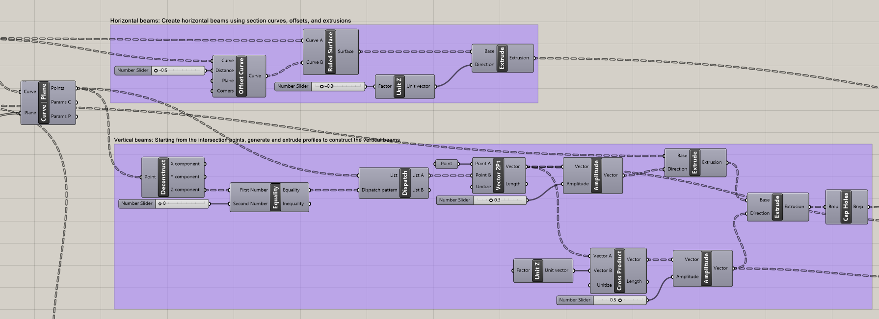
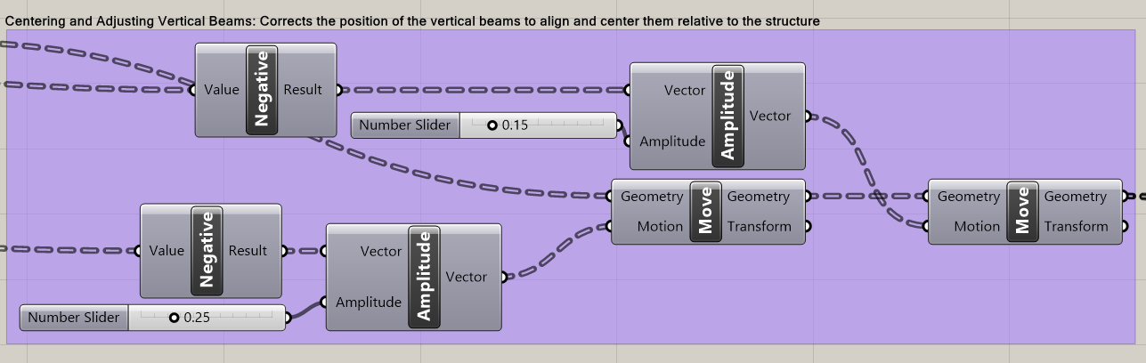
The result is a lightweight radial waffle structure whose geometry updates automatically whenever the main tower parameters are modified.
Stage 3 – Fabrication Preparation
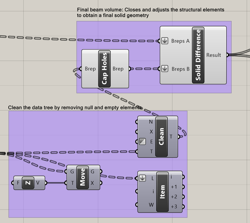
The vertical and horizontal beams are automatically intersected in Grasshopper to generate the assembly joints required for fabrication, after applying cleaning null data to avoid possible future errors.
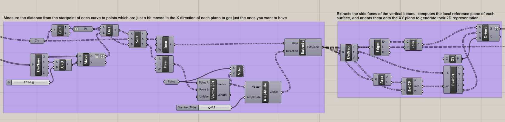
Once all intersections are resolved, each beam is individually extracted from the three-dimensional model and projected into the XY plane. This produces a complete set of two-dimensional fabrication drawings while preserving the geometry of every curved element.

Stage 4 – Nesting for Laser Cutting
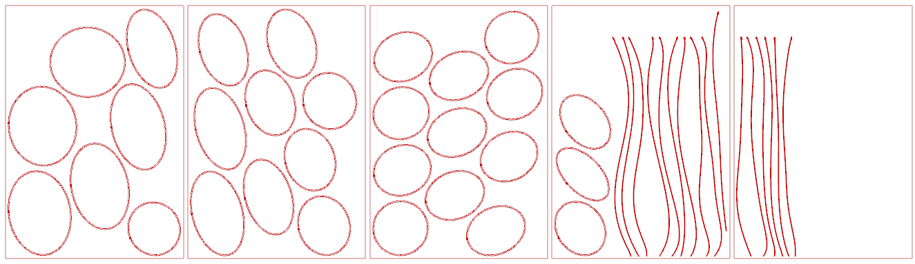
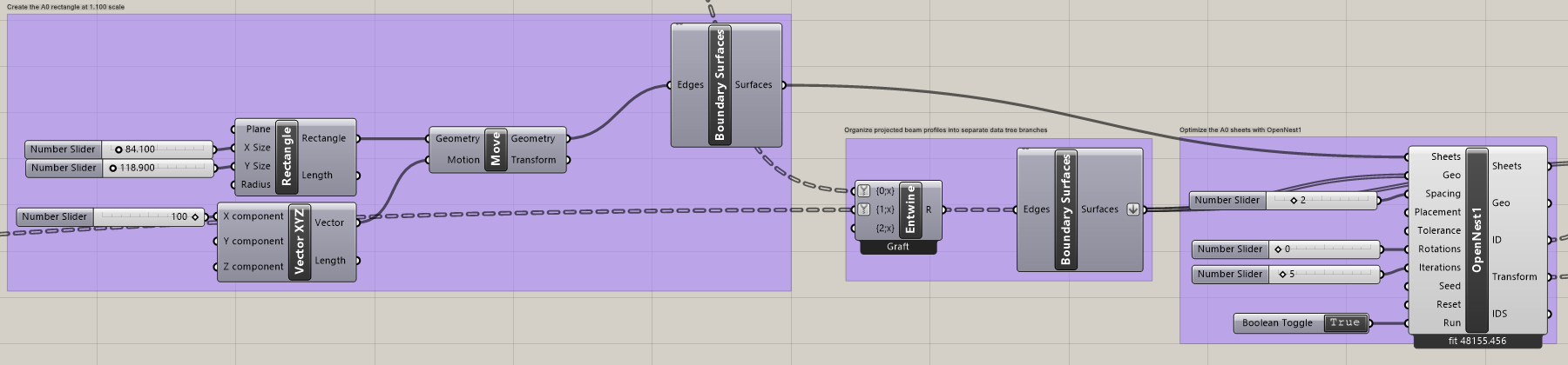
Once all beam profiles have been projected into 2D, the next step is to prepare them for fabrication. First, an A0 sheet (1189 × 841 mm), representing the physical laser-cutting board. The sheet is then translated away from the model to provide a clean workspace for the nesting process.
The projected profiles are first organized into separate data tree branches using the Entwine component, keeping the horizontal and vertical beam profiles as independent groups. Preserving this data structure is essential because both groups require different labeling strategies while maintaining their relationship throughout the workflow.
Since the projected pieces are initially represented as closed curves, Boundary Surfaces converts each outline into a planar surface. OpenNest uses these surfaces to calculate the occupied area of every piece, allowing it to optimize their arrangement efficiently on the A0 sheet.
Finally, all planar pieces are passed to the OpenNest plugin, which automatically computes an optimized layout by minimizing wasted material while respecting the specified spacing, rotation, and fabrication tolerances. The result is a compact arrangement of all structural components, ready for laser cutting.
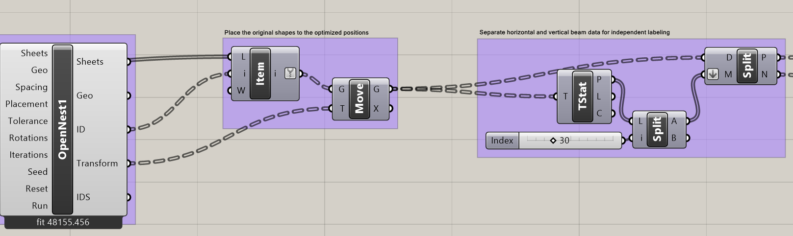
After OpenNest computes the optimal arrangement of all pieces, the resulting transformation matrices are applied to the original projected beam profiles using a Move component. This transfers the original geometries to their optimized positions on the A0 sheet while preserving their exact shape and topology.
The nested pieces are then separated into horizontal and vertical beam groups. The Tree Statistics component first analyzes the data tree structure generated by OpenNest, while Split List and Split Tree divide the nested geometry according to the number of horizontal and vertical beams.
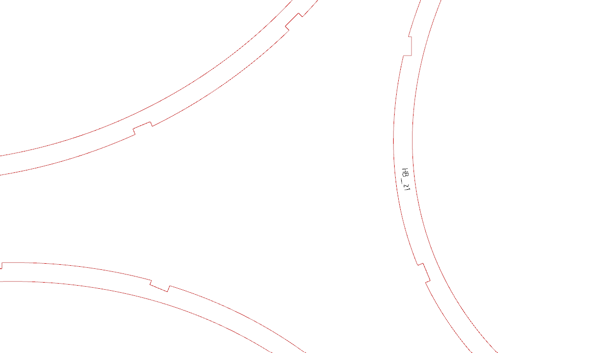
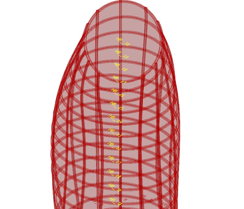
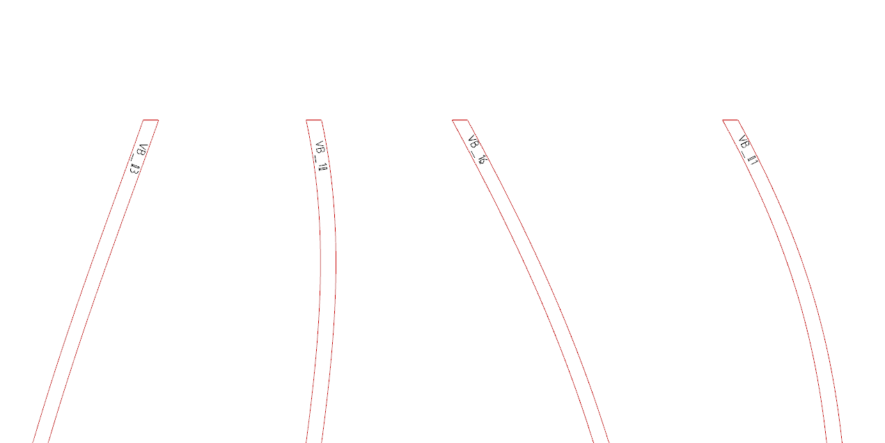
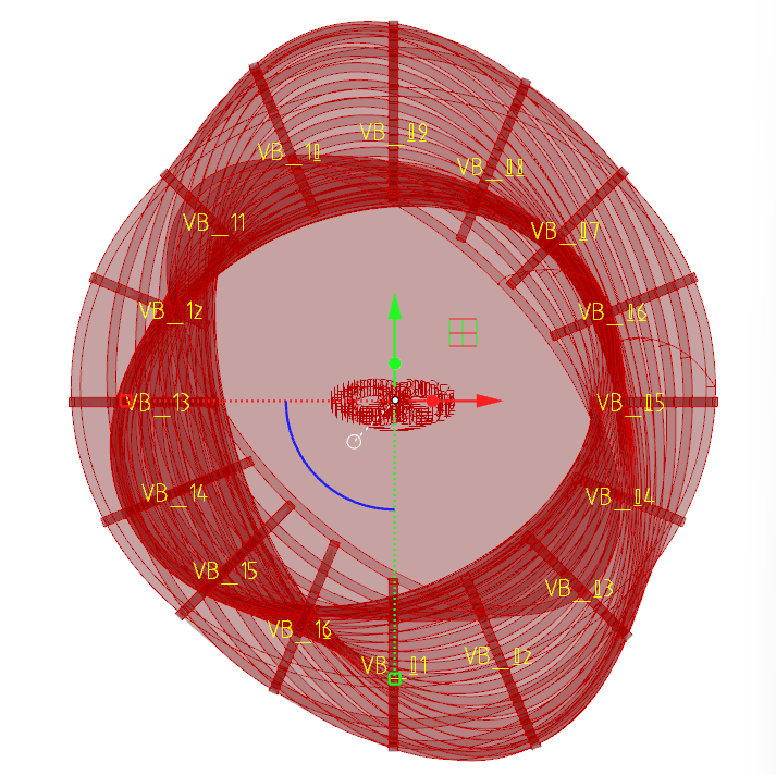
To facilitate assembly, each laser-cut piece is automatically assigned a unique identifier. Horizontal beams are labeled HB_01–HB_30, while vertical beams are labeled VB_31–VB_46 using the Series and Format components.
A placement plane is then computed for every beam by evaluating its outline curve, aligning the plane with the local tangent, and offsetting it toward the interior of the profile. Finally, the Text component generates the label geometry at the calculated position, ensuring that each piece is clearly identified for fabrication and assembly.
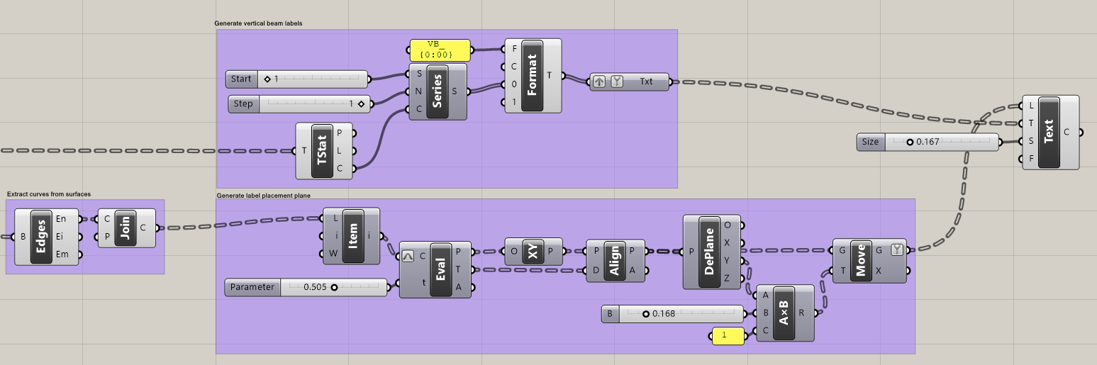
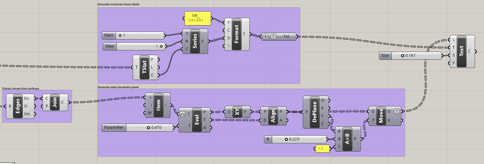
The same identifiers are also displayed within the three-dimensional model, creating a direct correspondence between the digital structure and the fabricated components. This allows each physical beam to be immediately associated with its exact location, orientation and sequence during assembly.
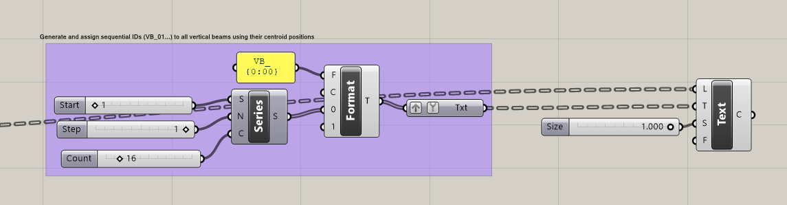
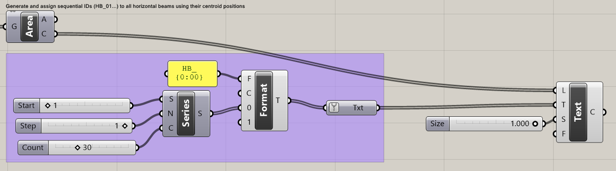
This integrated workflow establishes a continuous link between parametric design, digital fabrication and on-site assembly, ensuring that all components remain consistently organized from the initial model to the final construction.
Script Capabilities
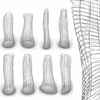
One of the main strengths of a parametric workflow is the ability to generate radically different design outcomes simply by adjusting a few key sliders — without modifying the underlying script logic. The following variations demonstrate the range of forms that can be produced from the same definition.
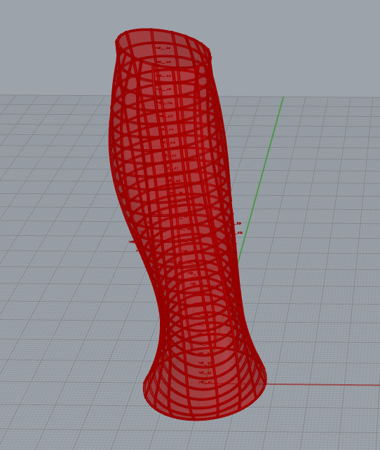
- Variation 1 — Base Tower: The base configuration uses the default slider values: 30 floors at 3.5m height, radio of 40m and 31m, a torsion angle of 0.78 rad (≈45°), and a moderate spiral displacement of 1.6m and 0.8m in X and Y respectively. The result is an organic, slightly twisted tower with a characteristic silhouette — wide at the base, narrowing towards the middle, and opening again near the top.
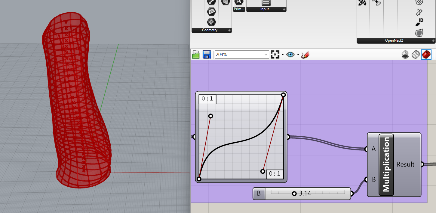
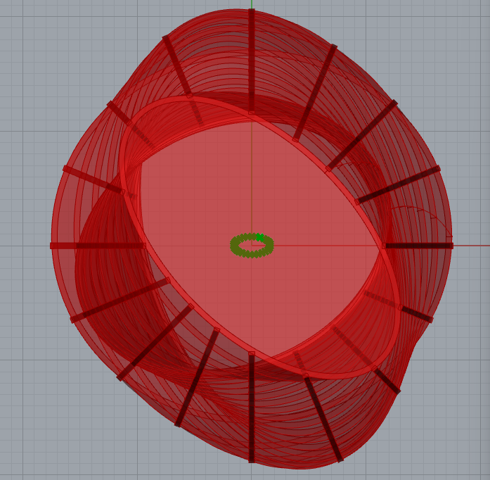
- Variation 2 — Increased Torsion: By increasing the torsion angle slider from 0.78 to 3.14 rad (180°), the tower undergoes a full half-rotation from base to top. The overall silhouette is maintained, but the structural grid now follows a much more dramatic spiral path along the surface. This variation demonstrates how a single slider controls the entire rotational character of the tower, from a subtle lean to a full architectural twist. (Modified parameter: Torsion Angle → 0.78 to 3.14 rad).
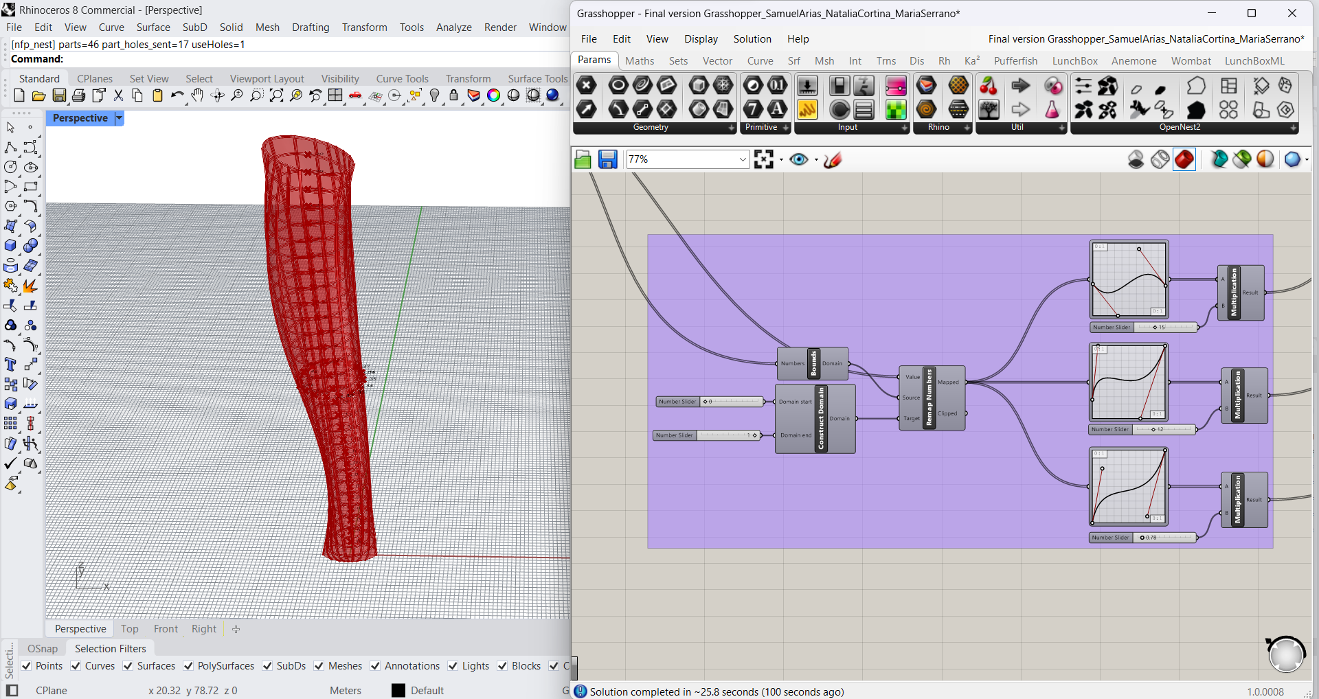
- Variation 3 — Slender Profile with Modified Graph Mapper Curves: Here two changes are combined: the maximum radius sliders are reduced (from 40 to 15 and from 31 to 12), producing a much more slender tower; and the Graph Mapper curves for both radii are reshaped to be more asymmetric and pronounced. The result shows how the same structural logic adapts to a completely different proportional system — the waffle grid automatically recalculates to fit the new surface, with no manual intervention required. (Modified parameters: Radius 1 max → 40 to 15 / Radius 2 max → 31 to 12 / Graph Mapper curves reshaped)).
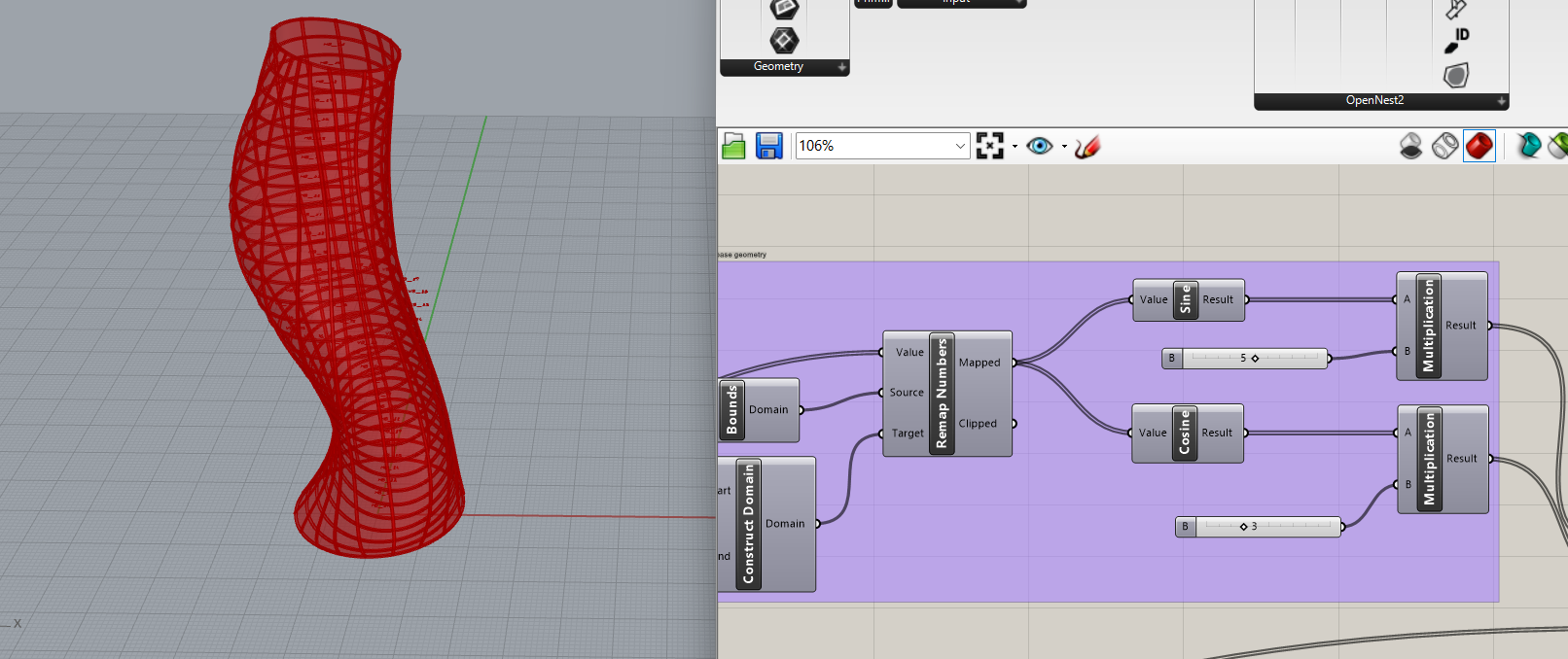
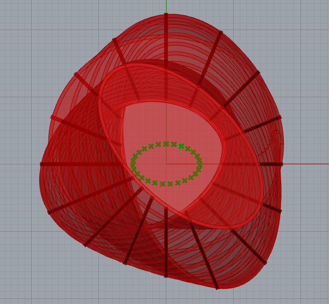
- Variation 4 — Exaggerated Spiral Displacement: The X and Y amplitude sliders controlling the sine/cosine displacement of the section centers are pushed to extreme values (5.0 and 3.0). The tower’s vertical axis is no longer straight but describes a wide, flowing curve in space — almost sculptural in character. The plan views (top) show clearly how the elliptical sections drift off-center along the height, and how the radial structural ribs follow that movement automatically. This variation highlights the expressive potential of the trigonometric displacement system and how it interacts with the structural grid. (Modified parameters: X Amplitude → 1.6 to 5.0 / Y Amplitude → 0.8 to 3.0).
Plugins Used
This project was developed using native Grasshopper and Rhino components only, with one exception for the fabrication preparation stage:
OpenNest
OpenNest — Free, open-source nesting plugin for Grasshopper developed by Petras Vestartas.
OpenNest was used to arrange all the flat pieces (vertical ribs and horizontal rings) onto standard laser-cutting sheets automatically. Without a nesting tool, placing dozens of irregular pieces manually onto sheets is time-consuming and wastes material.
In this project, OpenNest handles:
- Automatic placement of all pieces within a defined sheet boundary (e.g. 600×300mm or 1200×600mm)
- Rotation of pieces to minimize wasted material
- Sheet pagination — if pieces don’t fit on one sheet, OpenNest generates multiple sheets automatically
It can be downloaded here: https://www.food4rhino.com/en/app/opennest
All other components — surface generation, graph mappers, torsion, attractor logic, waffle structure, solid difference for slots, and labeling — are 100% native Grasshopper/Rhino with no additional plugins required.