A “how to guide”
Štepán Remetei, Michaela Tóthová
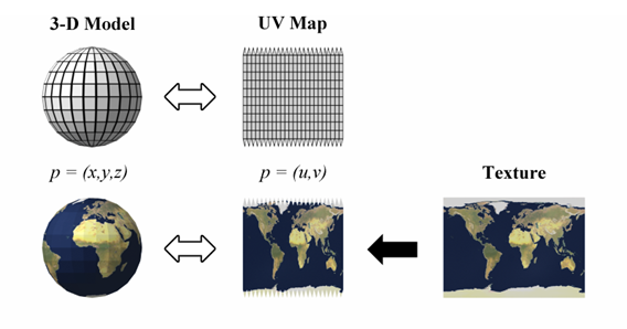
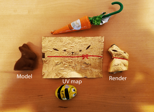
What is UV mapping?
UV mapping defines how a 3D model will appear. It is a 3D process of analysing and then projecting a 3D model´s surface onto a 2D plane. The process involves creating a map that assigns specific coordinates, to every point on the model’s surface. These coordinates are u and v, from which the term UV mapping originates. It is not the UV as in ultraviolet. UV coordinates then influence how textures and images are applied to the model. High quality UV mapping ensures that the surfaces are detailed and more accurately placed onto the model resulting in a more realistic visual.
UV mapping can be used in creating textures for video games, film, CGI, product design, rendering, creating in VR or AR. If UV mapping is not done properly, textures on the final 3D model end up looking unaligned, stretched, warped or compressed. UV mapping is therefore significant in preventing these distortions from happening.
The process of UV mapping
This process can be divided into four stages. Defining the seams, unwrapping into 2D, creating a UV layout and finally texture application
SEAMS
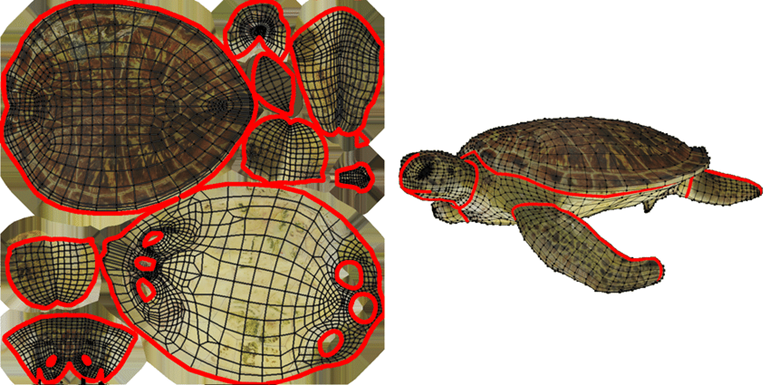
When flattening the 3D into 2D UV maps there need to be some cuts made on the 3D model (as in clothing patterns or like the cuts made in an orange peel to flatten it out). These cuts are then “seamed” back together in the 3D model. Which can often result in discontinuities or distortion of the texture on the model. To minimise discontinuities the seams are usually strategically placed in areas that are less visible, on natural edges of the object.
UNWRAPPING
It is the process of flattening a 3D model into a 2D “UV map” to allow for the application of 2D image textures without stretching or distortion. Usually, it is done by cutting the 3D mesh and laying the resulting 2D shapes flat in a layout. There are different methods of unwrapping. Different methods are good for different shapes.
- Conformal unwrapping: it minimizes angle distortion by using a specific algorithm, making it good for organic shapes.
- Angle Based unwrapping: aims to keep the angles of the 3D mesh consistent in the 2D map, which is useful for hard surfaces.
- Optimization-based methods: they use complex algorithms to optimize the UV map by trying to minimize distortion, boundary length, or other factors, often while maintaining bijectivity/no overlapping
- Follow Active Quads: Stretches the UV layout of the active quad to its neighbours, ignoring non-quad faces.
- Seam-based unwrapping: jointly optimizes the seams and the parameterization for better results.
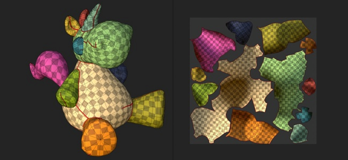
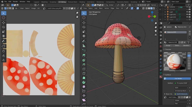
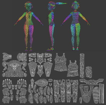
UV LAYOUT/MAP
The product of unwrapping the 3D model along its seams is the UV layout or map. A 2D plan of a 3D model. It uses the U and V axes in 2D space from which the name comes from. U and V axes are used because axes X, Y and Z are already taken in the 3D space.
TEXTURE APPLICATION
After having an UV map we can apply the 2D texture onto the map by linking the UV coordinates of the UV map with the XY coordinates of the texture image. This will allow a precise placement and manipulation of textures in 3D.
Types of UV mapping
Based on the 3D object we differentiate four main types of mapping:
Planar = projects a texture from a single flat model like a wall or a floor
Cylindrical = wraps a texture around an object as if it was a cylinder, good foe working with pipes, bottles or arms
Spherical = projects a texture onto a sphere, good for planets, heads,…
Box = uses six orthogonal projections, good for cubic models
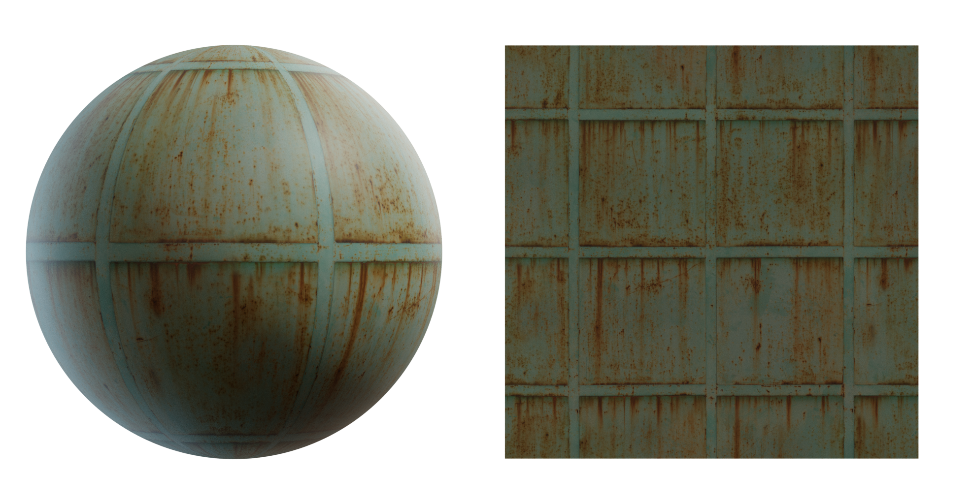
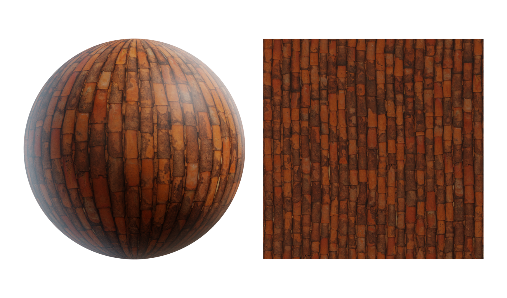
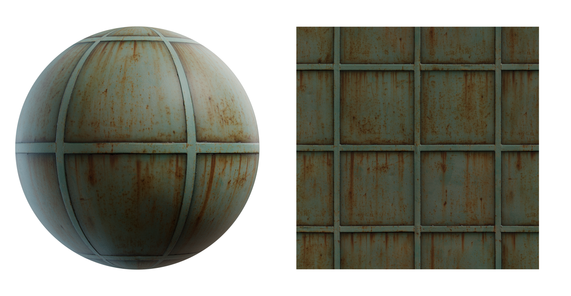
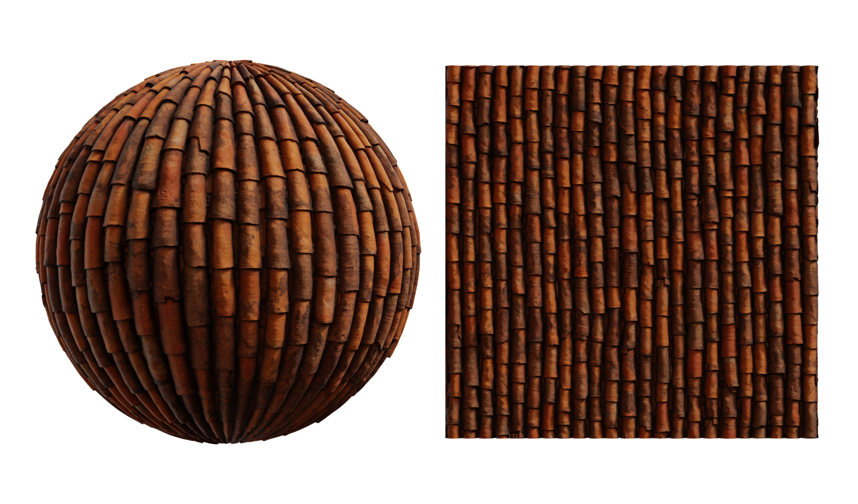
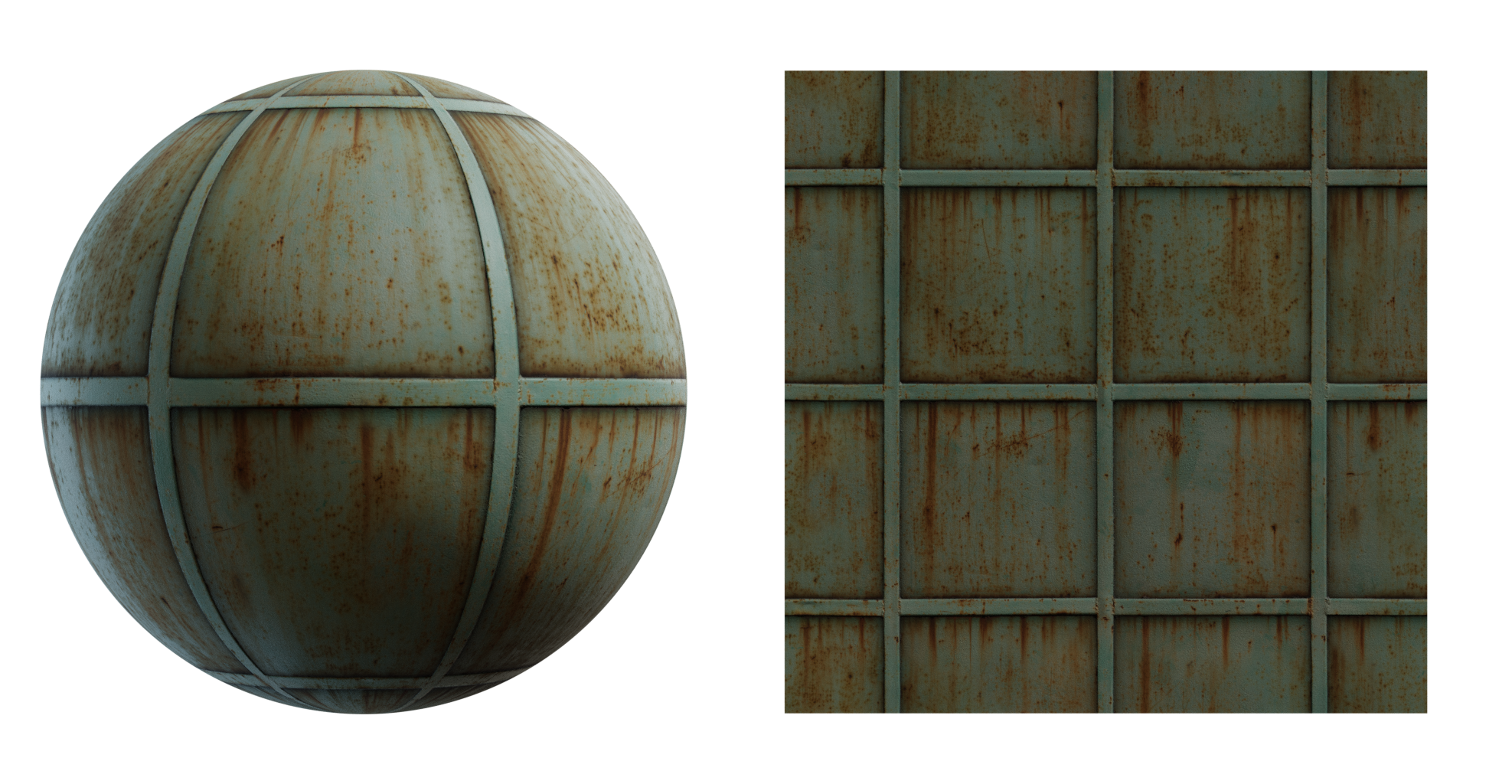
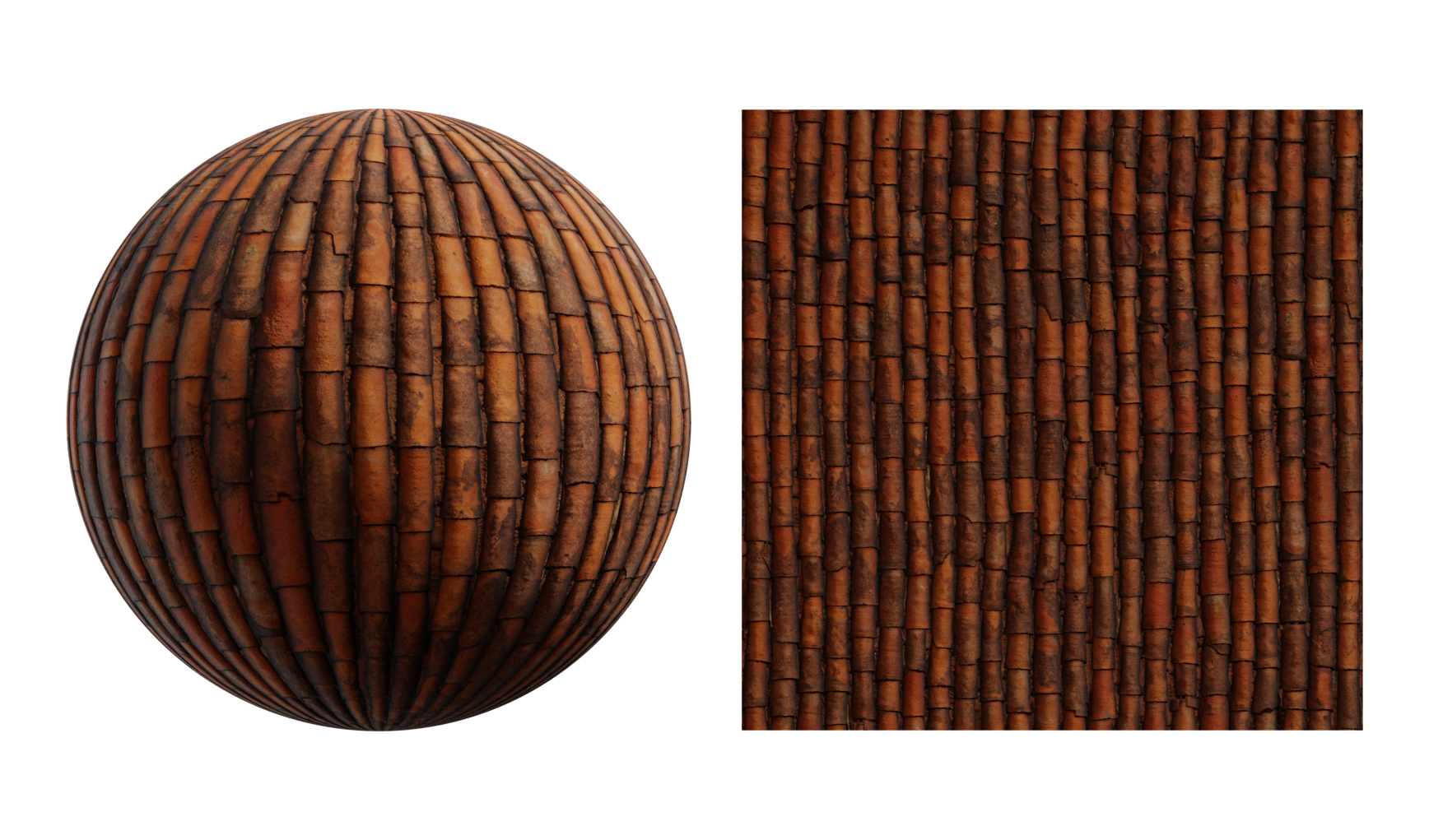
Texture mapping
Texture map is a 2D image/texture that is applied onto a 3D surface to add colour and detail. This is done with the UV map´s coordinates which determine the specific points the texture map will be applied to the surface. There are multiple types of texture maps which work together to create realistic surfaces on 3D models.
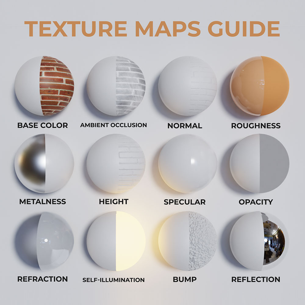
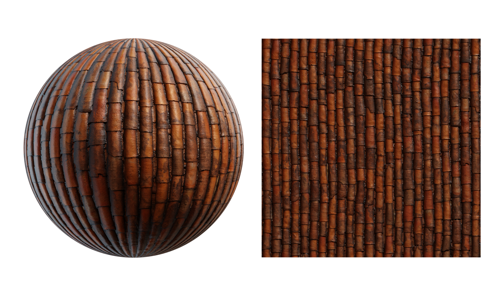
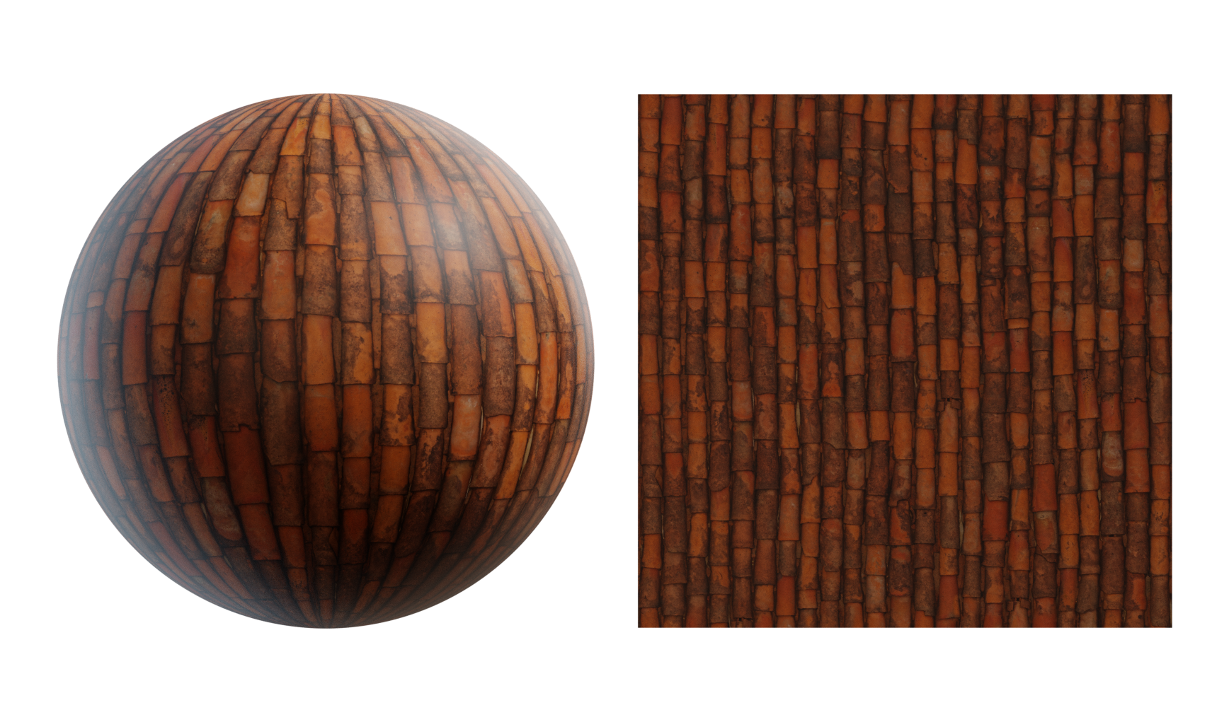
DIFFUSE/BASE COLOR MAP/ALBEDO
Provides the base colour and pattern for a 3D object. Basically, a 2D image/colour that determines the look of the material.
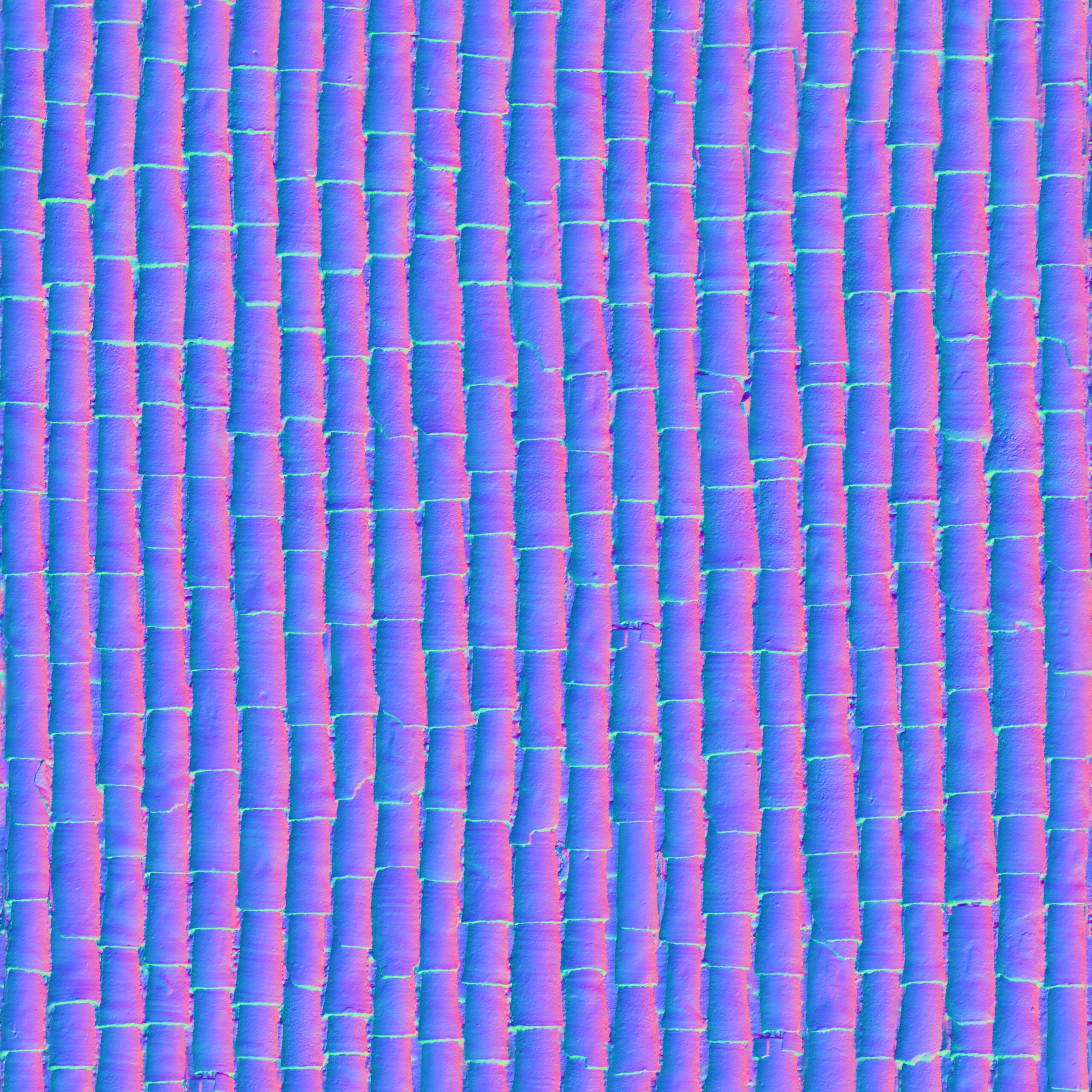
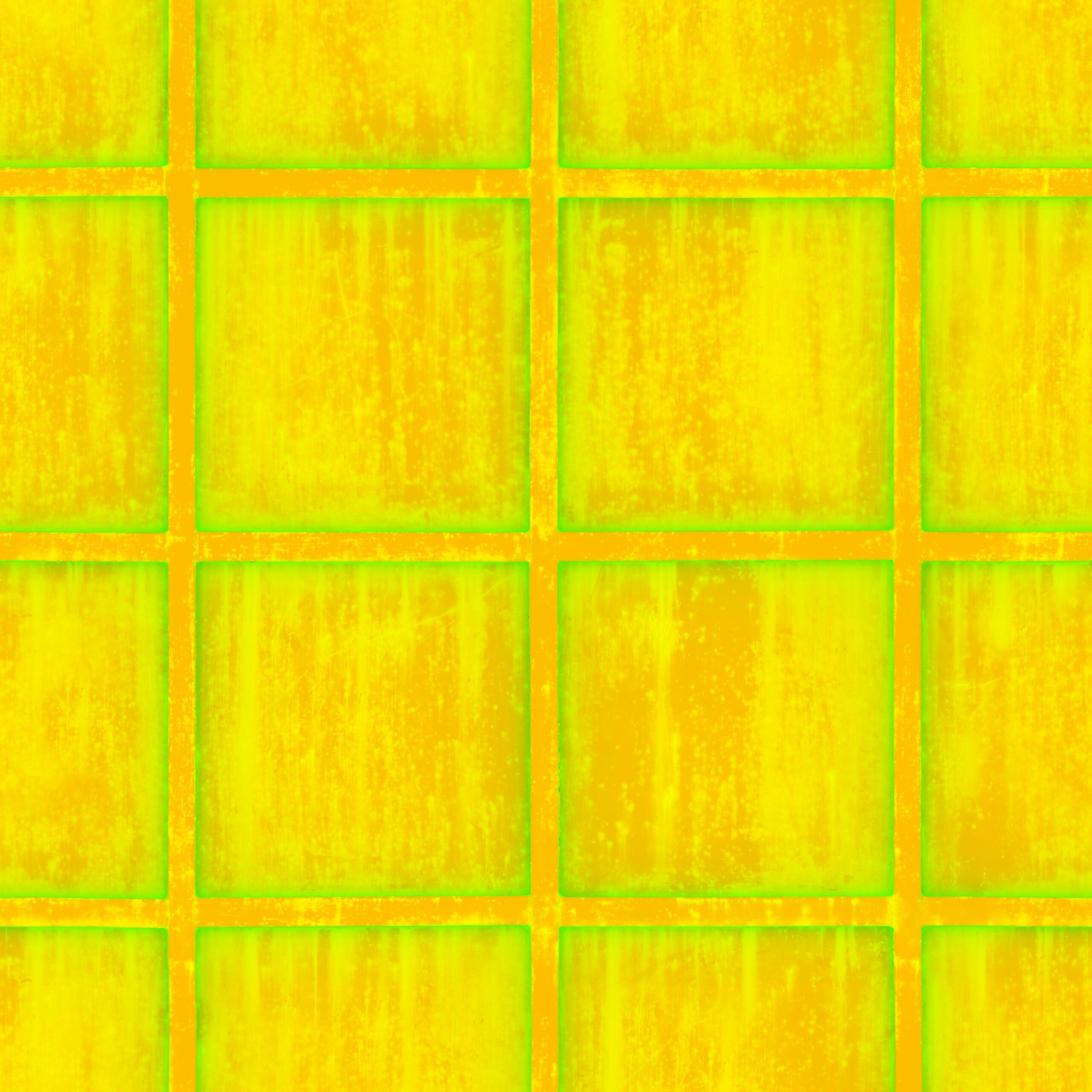
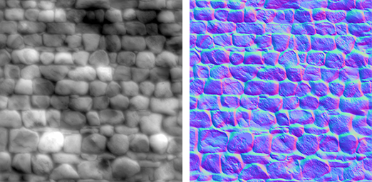
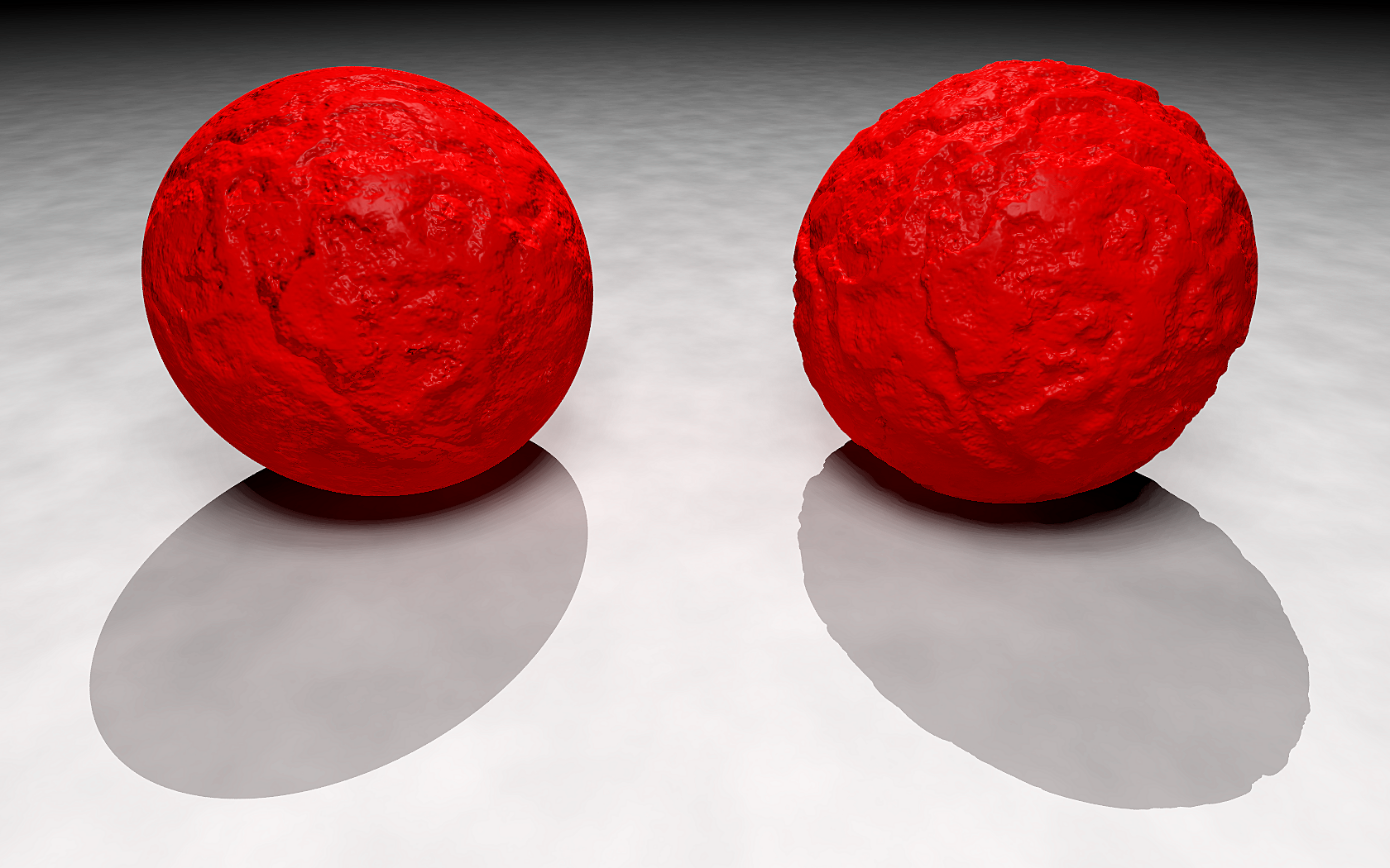
NORMAL MAP
Creates the illusion of surface detail by adding depth without altering the actual geometry, but by affecting how light interacts with the surface. It uses an RGB image where each channel corresponds to a direction (X, Y, Z) on the surface’s normal vector.
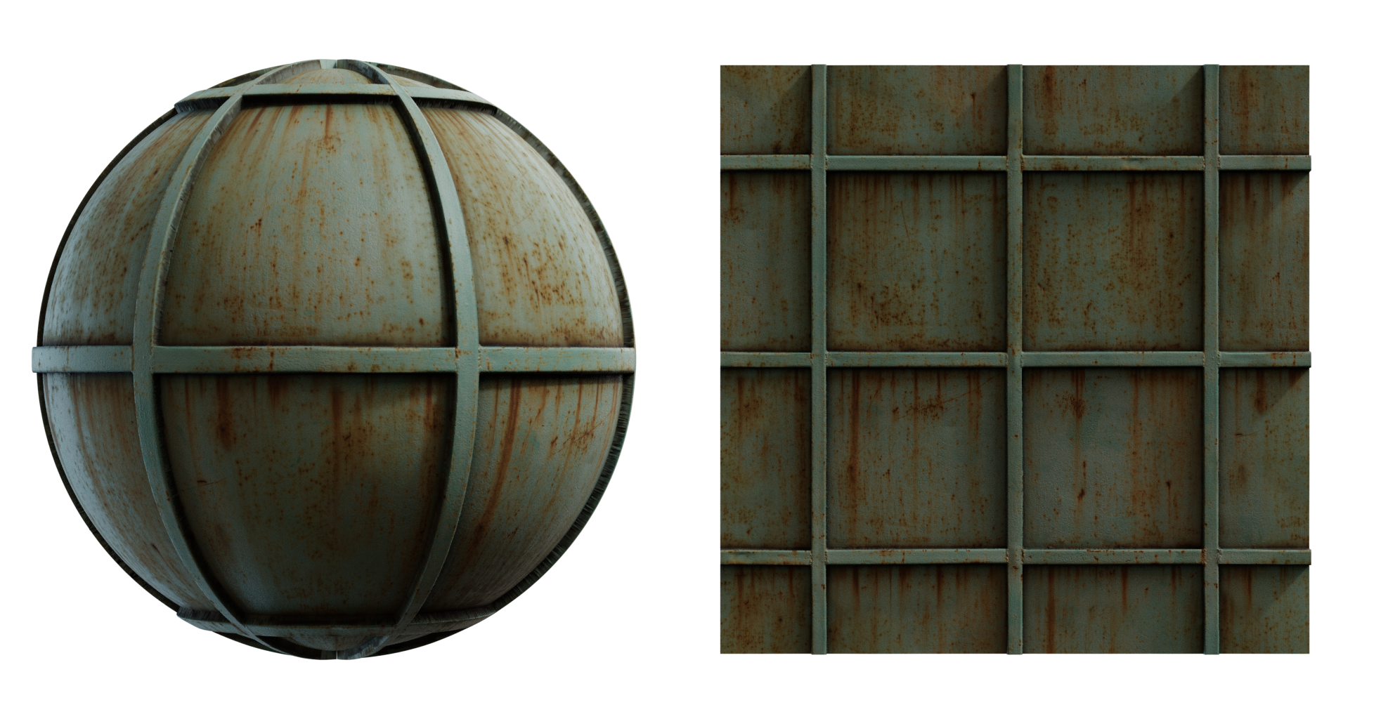
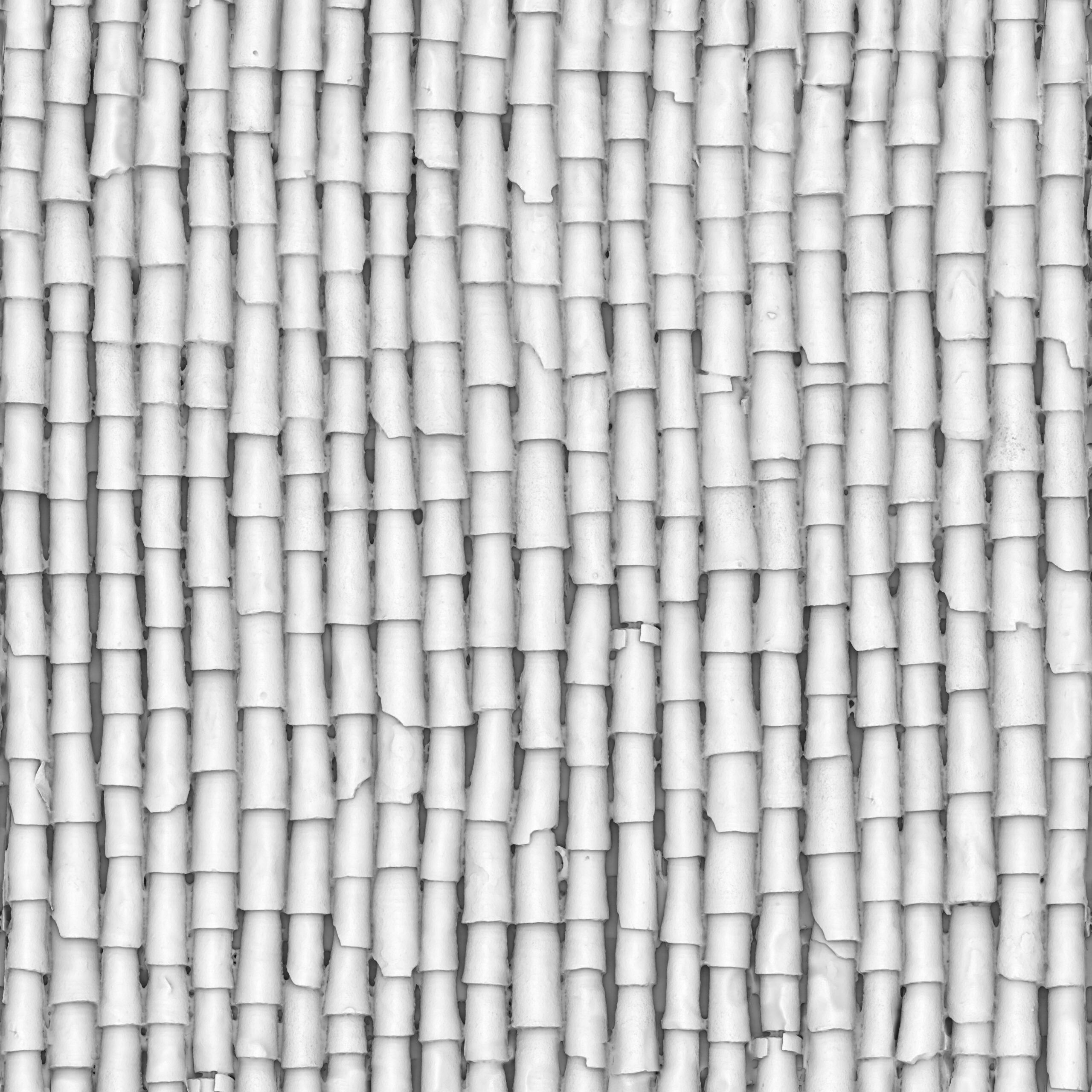
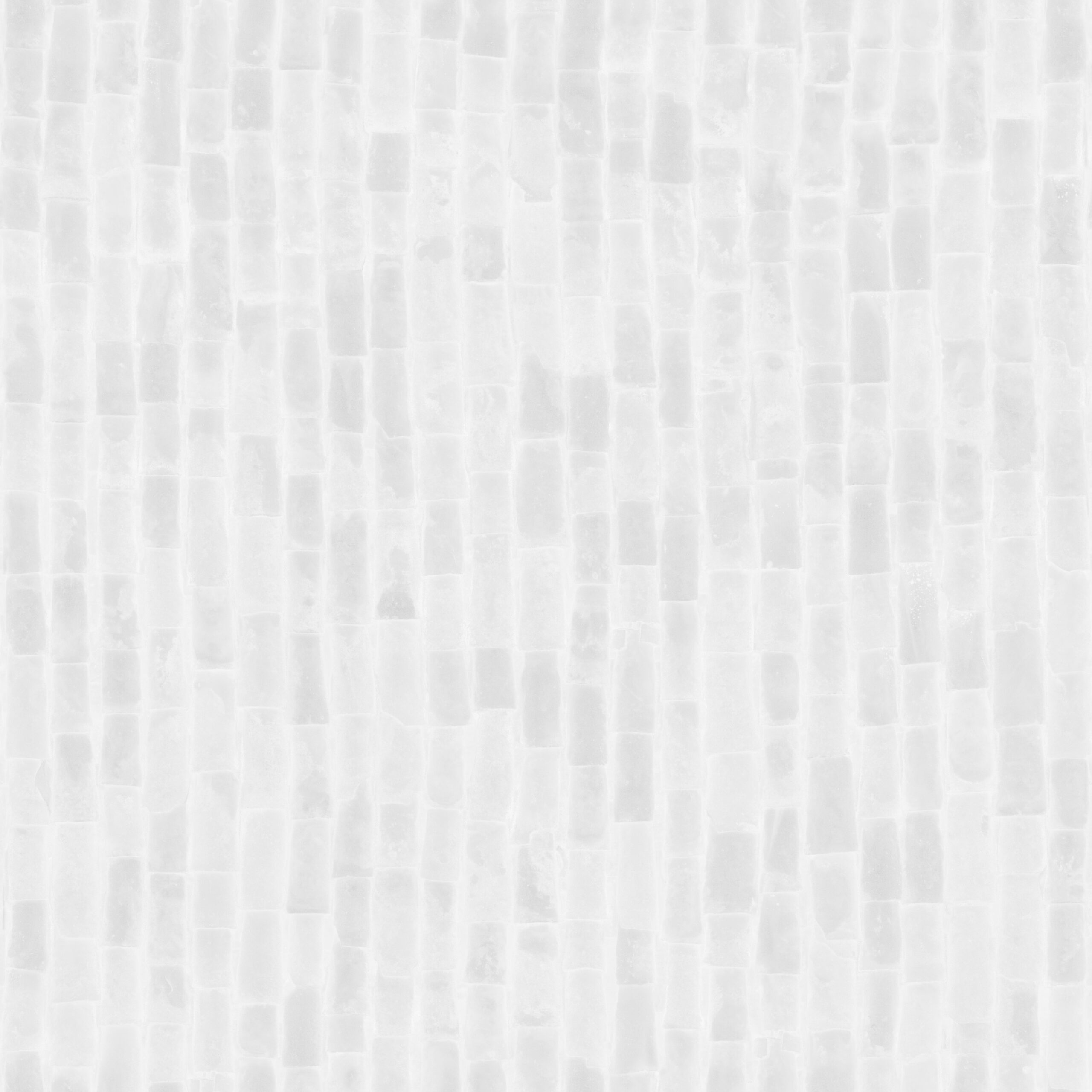
DISPLACEMENT MAP
Physically alters the geometry of the model, moving the vertices to create real depth and detail, unlike normal or bump maps. It defines surface’s topography, where white represents peaks, black represents valleys, and shades of grey represent levels in between.

AMBIENT OCCLUSION MAP
Adds soft, ambient shadows in areas where light would naturally be blocked. It simulates how objects or surfaces prevent ambient, non-directional light from reaching a point. Doesn´t affect the geometry.
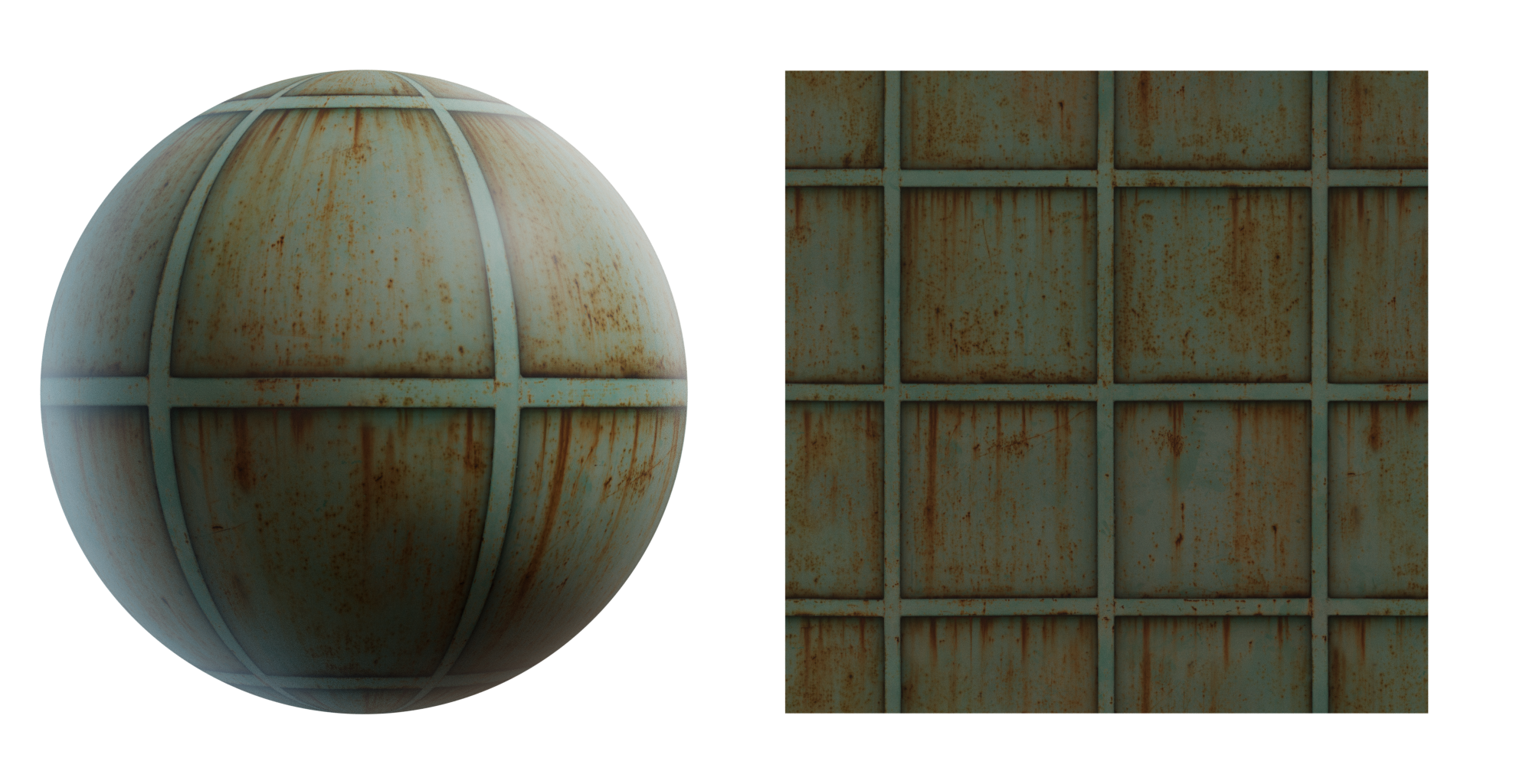
ROUGHNESS MAP
In physically-based rendering (PBR), this map controls how rough or smooth a surface is, affecting how sharp or blurry its reflections appear, by influencing how light scatters across it.
METALNESS MAP
Determines which parts of the surface behave like metal. It determines how much a surface reflects its surrounding.

EMISSIVE MAP
Determines which parts of the material emit their own light.
OPACITY MAP
Controls transparency, defining which parts of the texture are see-through.
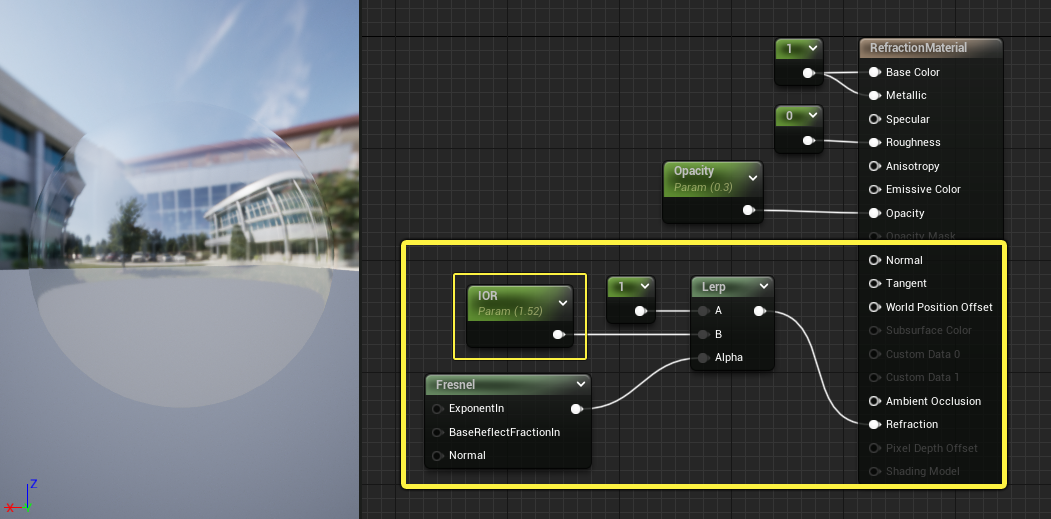
REFRACTION MAP
It is used to describe how light changes directions in a medium. Usually used when working with water or light.
BUMP MAP
Works in up and down direction to fake the texture on the surface, while not altering geometry of the model.
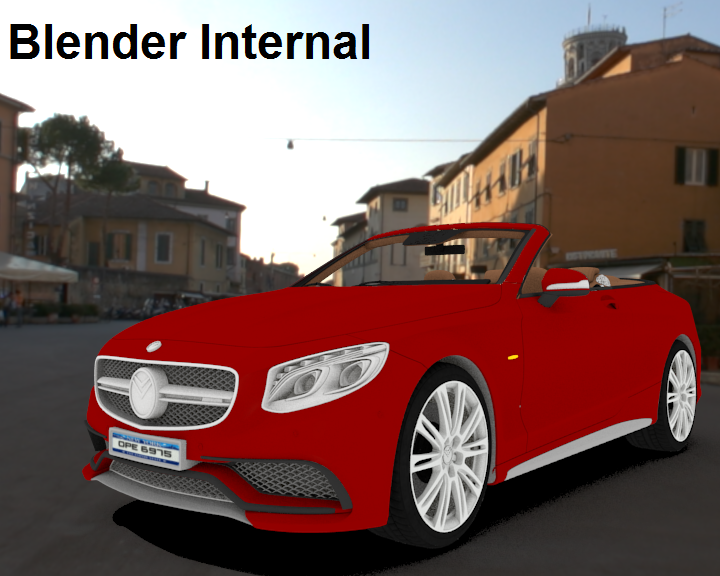
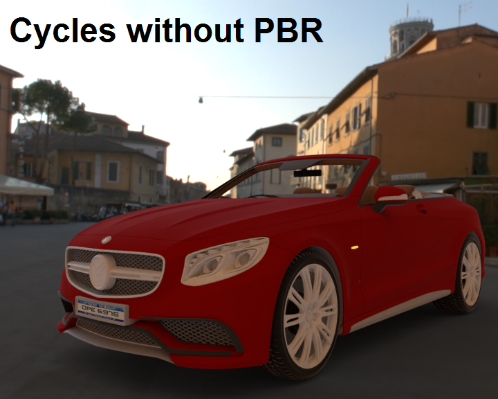
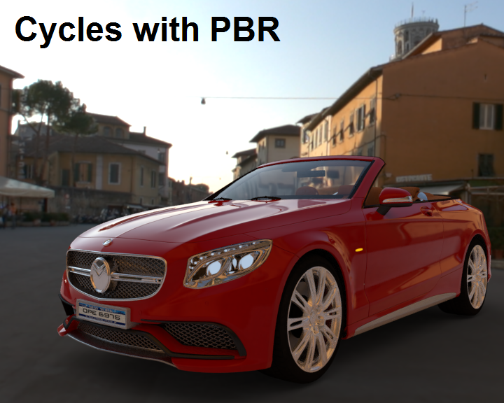
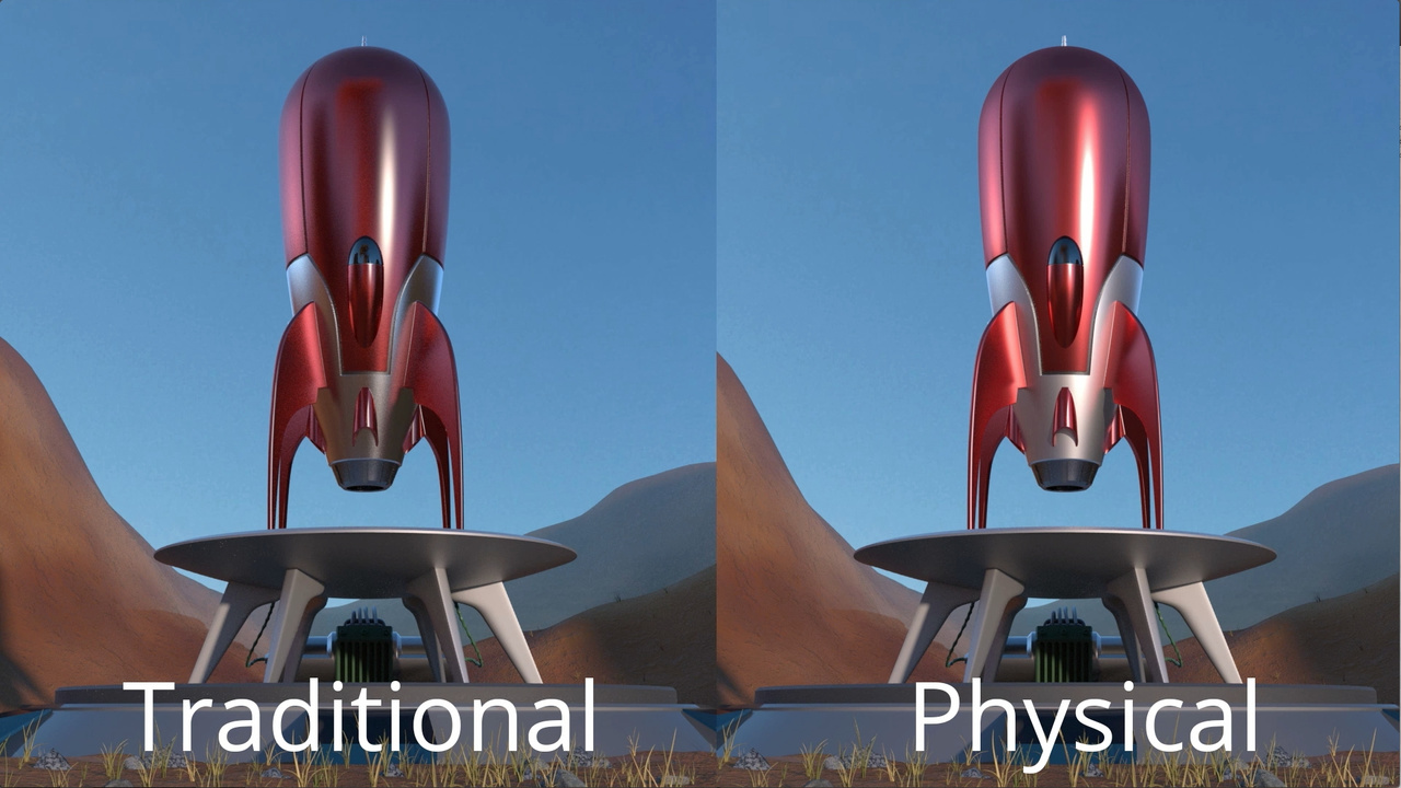
PBR VS NON-PBR
Physically based rendering uses accurate lighting and other physical properties to achieve photorealistic textures in 3D. Non-Physically based rendering uses artistic approximations, static lighting information and shaders to achieve a desired outcome. This makes non-PBR rendering far less consistent across different lighting conditions.
Out of the previously mentioned texture maps, opacity texture map, refraction texture map and bump texture maps are non-PBR.
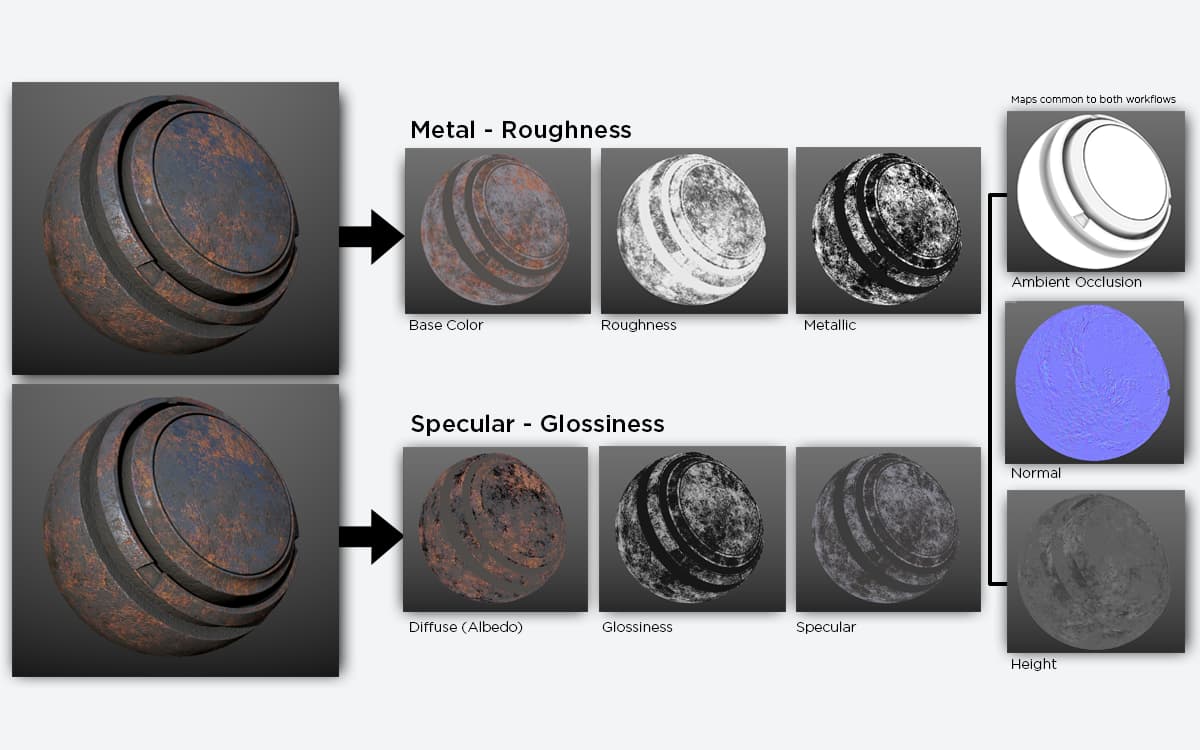
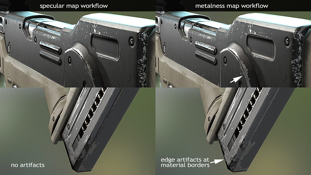
METALLIC ROUGHNESS VS SPECULAR GLOSSINESS WORKFLOW
The two workflows affect the look of the final 3D model by applying different maps to determine the shine/metal property of the material. The metallic/roughness workflow uses separate maps for metallic properties, to determine whether it is metal, and roughness properties to say how rough or smooth the material is. The specular/glossiness workflow combines these properties into different maps, where the specular map controls reflectivity and color for both metallic and non-metallic parts, and the glossiness map controls smoothness. When working, one has to choose one of these workflows. The benefits of metallic roughness are that it is a bit simpler to use as it uses fewer textures, but may be more limiting. The specular glossiness workflow is much more adjustable, but can be more complex and therefore harder to work with.