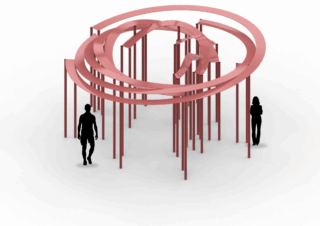
Aim
Traditional modelling tools can create basic forms, but with Grasshopper we can use mathematical functions to generate unique and dynamic geometry. For this project, I decided to create a pavilion based on a cosine wave. Starting from two simple circles, I used parametric design techniques to deform the geometry and create a flowing, organic structure. The shape changes according to adjustable parameters such as wave height, frequency, and pavilion size, allowing many different design variations to be generated from the same definition.
The goal of the project is to demonstrate how mathematical functions and parametric modelling can be used to transform simple geometry into an expressive architectural form.
Project Result
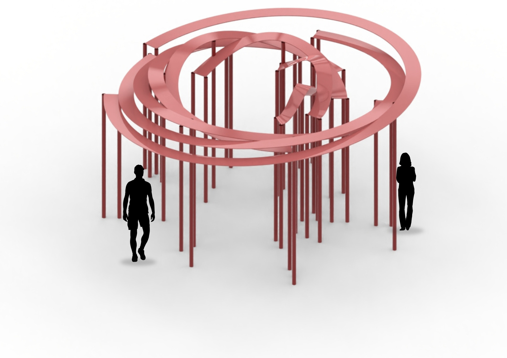
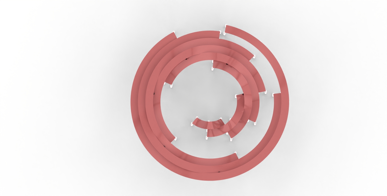
Top View – Spiral Pattern
Grasshopper Script

1. Create the Base Geometry
The design process begins by creating the base arc that defines the overall footprint of the pavilion. The radius and angle sliders control the size and opening of the arc, allowing the overall geometry to be adjusted before any further modifications are applied.
Modifiable parameter: Radius, Start Angle, End Angle
Changing these parameters modifies the overall dimensions and curvature of the pavilion, directly influencing its footprint and overall proportions.


2. Rotate the Reference Curve
The generated arc is rotated to its desired orientation. This step positions the reference geometry correctly and prepares it for the following operations.
Modifiable parameters: Rotation Angle
Adjusting the rotation angle changes the orientation of the pavilion without affecting its geometry.

3. Generate the Wave Pattern
The reference curve is divided into evenly spaced points. Their vertical positions are modified using a Graph Mapper, creating the wave pattern that defines the pavilion’s characteristic form.
Modifiable parameters: Number of Divisions, Graph Mapper
These parameters influence the smoothness and amplitude of the wave, resulting in different surface patterns and architectural expressions.


4. Reconstruct the Wave Curve
The modified control points are used to generate a new interpolated curve. This reconstructed curve replaces the original arc and becomes the primary design curve used throughout the rest of the modelling process.
Modifiable parameter: Control Point Distribution.

5. Create the Offset Curves
An offset operation is applied to the reconstructed wave curve to generate parallel curves. These curves define the inner and outer boundaries of the pavilion elements and establish the overall structural width.
Modifiable parameter: Offset Distance.
Increasing the offset distance produces wider structural elements, while decreasing it creates a lighter and more compact design.


6. Generating the Structural Columns
The points along the offset curves are projected onto the ground plane using the Project component. The original and projected points are connected with Line components, creating columns that automatically extend to ground level regardless of the pavilion height.
Modifiable parameters: Ground Plane
The columns automatically adapt to the changing geometry while maintaining consistent contact with the ground.


7. Create the Pavilion Surface
The generated curves are combined using the Merge component and connected through a Loft operation. This creates a continuous surface that represents the main architectural shell of the pavilion.
Modifiable parameter: Loft Input Curves.
Different input curves generate different surface geometries, allowing variations in the overall pavilion form.

8. Generate the Structural Elements
The lofted surface is extruded to create thickness, while selected curves are converted into structural members using the Pipe component. Finally, all generated geometry is merged into a single output representing the completed pavilion model.
Modifiable parameters: Extrusion Height, Pipe Radius.
These parameters determine the thickness of the pavilion shell and the dimensions of the structural frame, significantly influencing both the appearance and the structural expression of the final design.

9. Visualizing the Final Model
The final geometry is displayed using Custom Preview components with assigned materials and colors. The model is visualized in Rendered display mode to improve presentation quality.
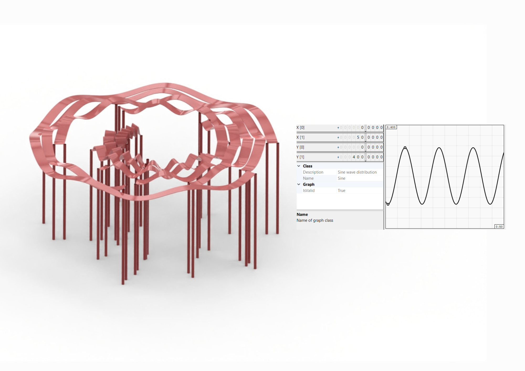
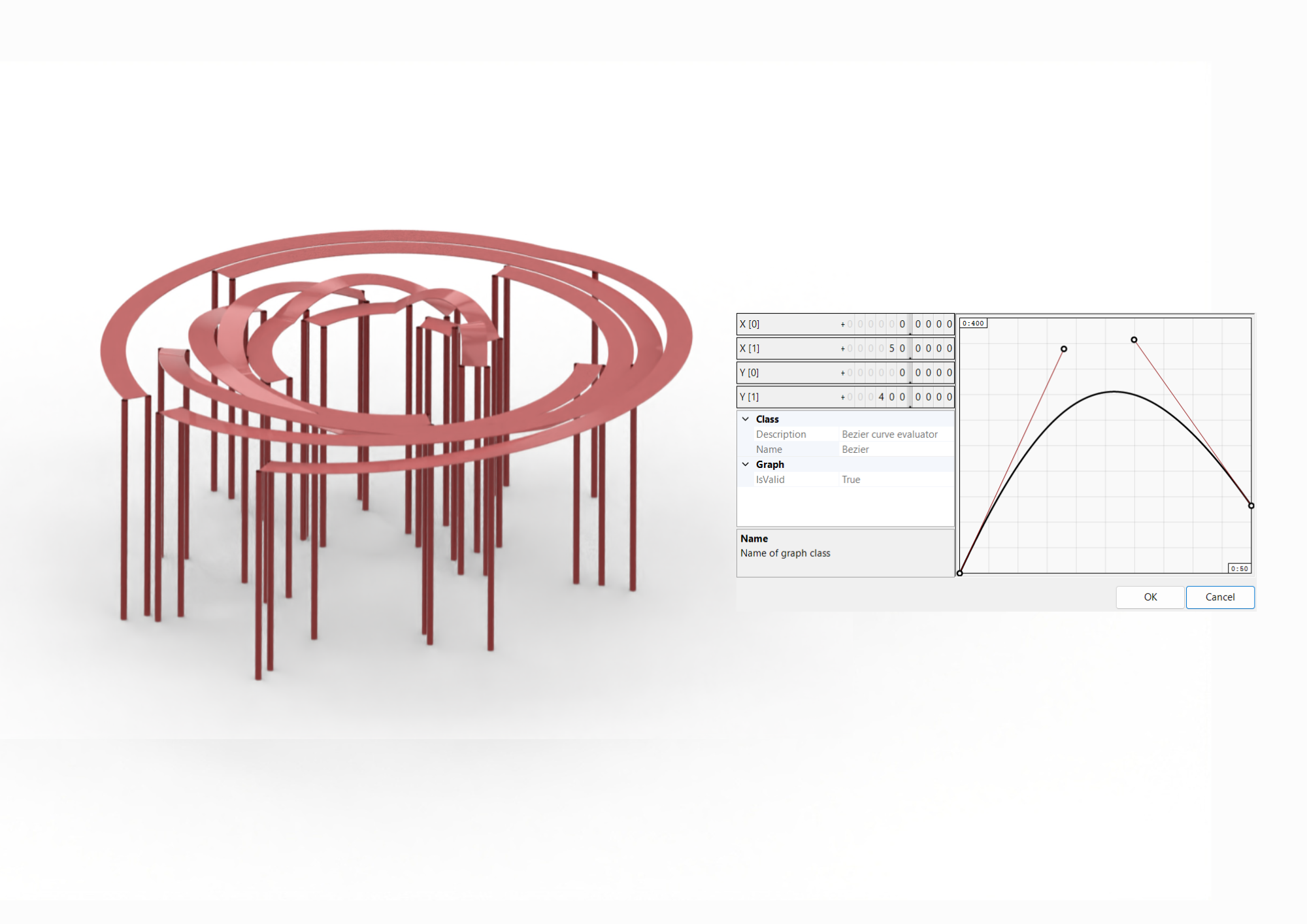
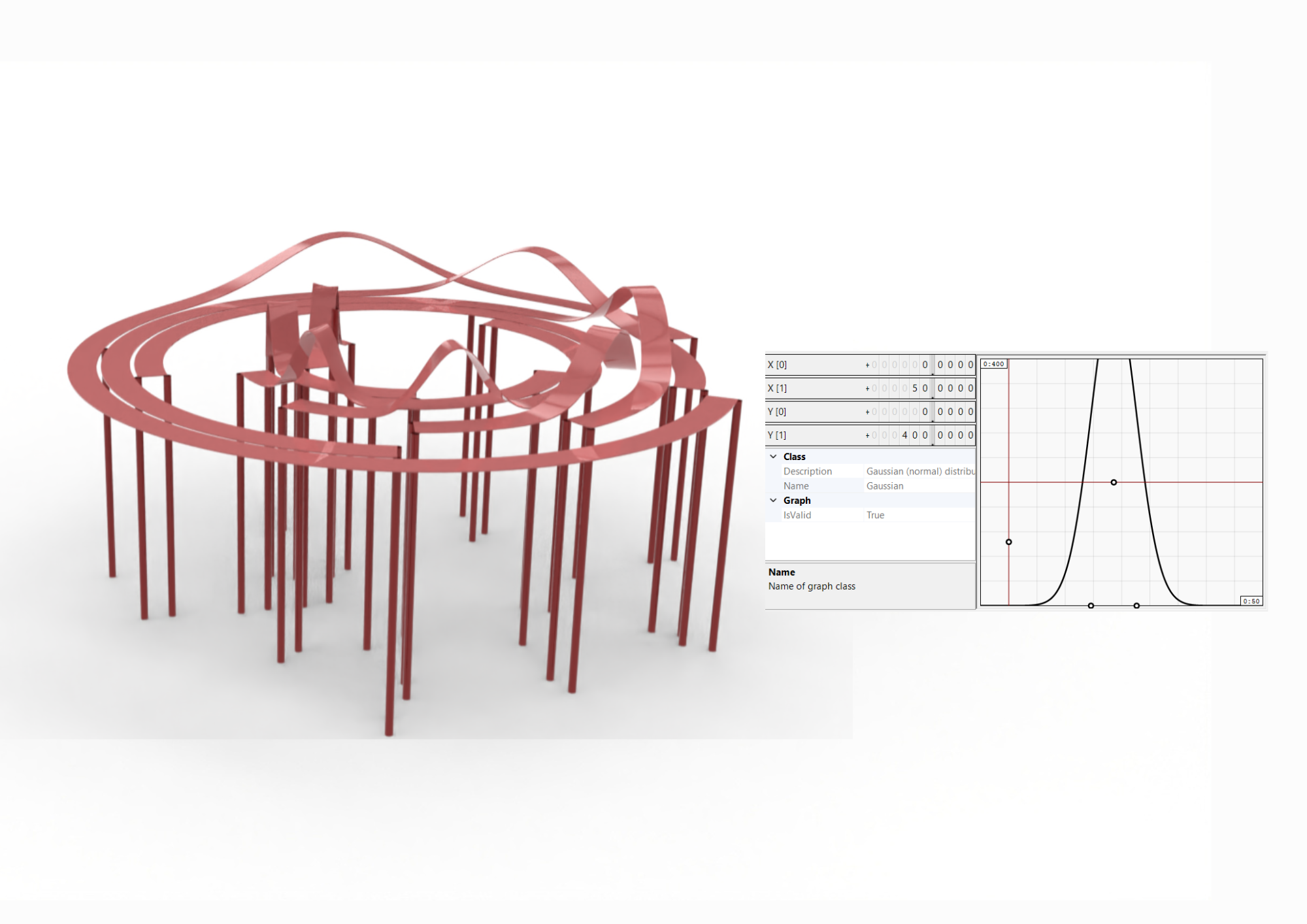
10. Ribbon Structure change through Graph Mapper
We can also change the structure of the pavilion using the Graph Mapper and Construction Domain instruments, changing its whole structure. We mainly use the Construction Domain to avoid lines overlapping each other. Here are some examples of how our final result can look:
Main Design Parameters
During the design process, several parameters can be adjusted to generate different pavilion variations while maintaining the same parametric workflow.
Arc Radius controls the overall size of the pavilion and defines the primary reference geometry.
Start & End Angle determine the opening of the base arc and influence the overall footprint of the pavilion.
Rotation Angle changes the orientation of the pavilion without modifying its geometry.
Number of Divisions controls the number of points generated along the curve, affecting the smoothness and level of detail.
Graph Mapper defines the wave profile by controlling the height and shape of the deformation applied to the curve.
Offset Distance controls the spacing between the inner and outer curves, determining the width of the pavilion elements.
Connection Line Length adjusts the height of the structural connection lines.
Extrusion Height defines the thickness of the pavilion surface.
Pipe Radius controls the diameter of the structural frame elements.
Software
Modeling: Rhinoceros 8 + Grasshopper
Visualization: Rhino Viewport
Link for a script :
Enjoyyy!