Concept
I got this concept from my passion for making wood furniture. Coming from a school that favors learning through experience, I was quickly led to experiment with materials, especially their resistance, their nuances, their qualities and their constraints.
Principal objectif :
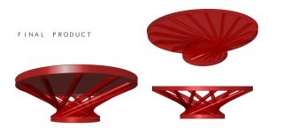
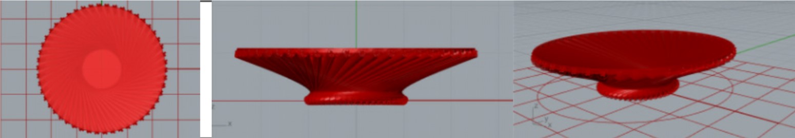
This modeling would allow me to visualize the assemblies, the amount of material, and the final look of the product I ultimately want to build.
I was inspired for this concept by an independent designer GARDAN Rachel who bases her dining table on a central leg system composed of four powder coated steel legs welded together.

The first idea:
In my first sketches I wanted to represent a massive table, which takes up the concept of crossing and centrality of R. GARDAN while giving a more natural and less industrial look. The idea is therefore to make it totally out of wood.
However, I had to limit the massiveness of the foot because the intersections were too numerous and the quantity of material too important. I lost my initial principle of a table that reveals the material and that is technically constructible.
The 1st Step:
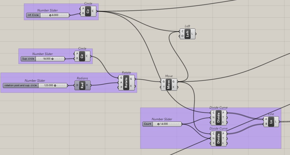
The first step consists in setting up the plans of the base and the top, to vary their diameter according to my preferences and to manage the height of the furniture.
Then comes the appearance of the legs. First I modify the rotation of the lower circle (of the base) with «rotate» and vary this rotation thanks to «radians» then I divide each of the circles into the same number of points «divide curve» which will allow me to link them together «line» to create the base of my foot and thus of each element composing it.
The 2nd Step:
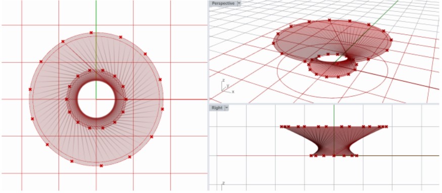
Next comes the creation of a surface for each circle, which I extrude to model the tray and the base. At the same time I take the lines created between each point to modify them into an object using «pipe» and unify them into a single geometry with «solid union».
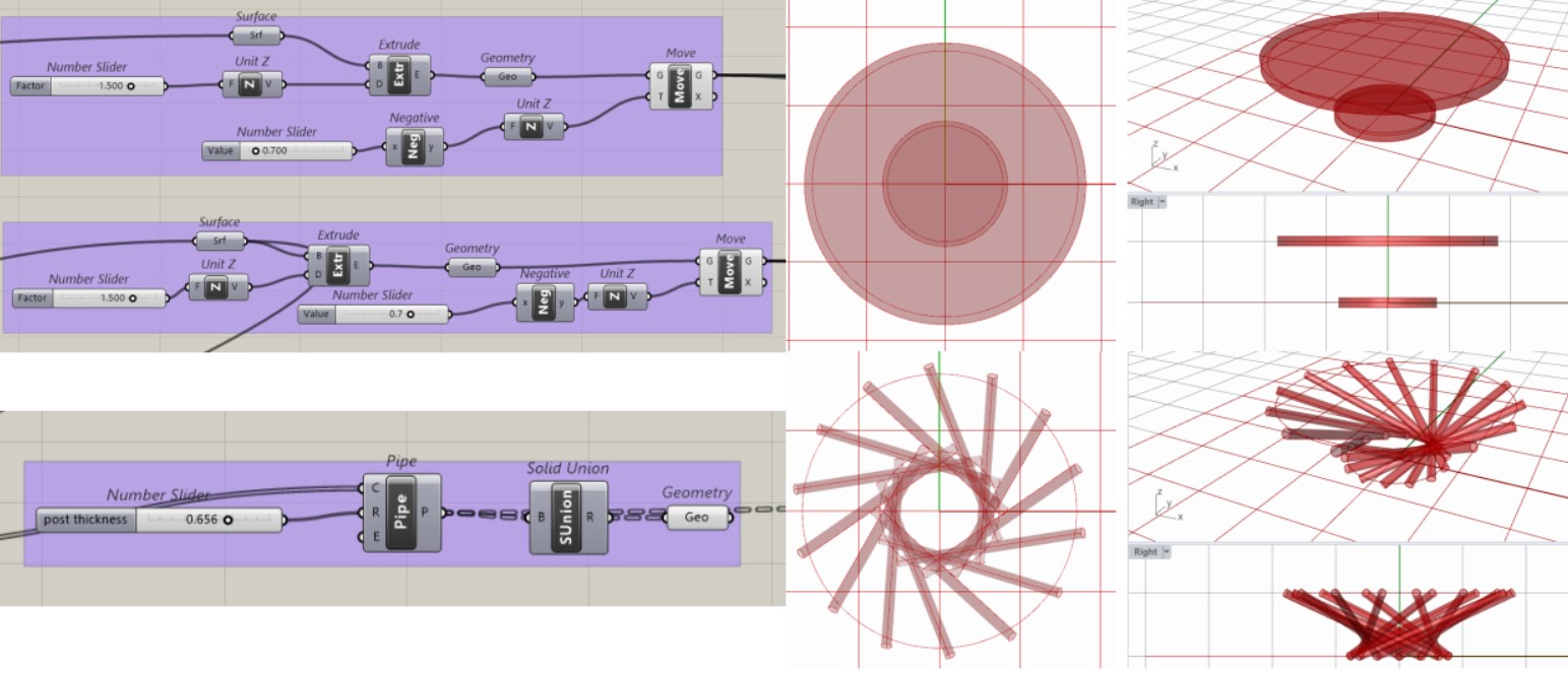
The 3rd Step:
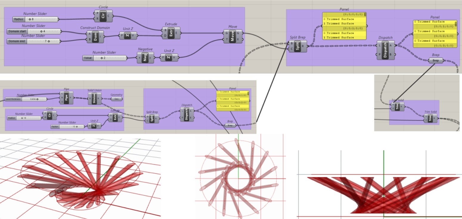
To make the dimensions of the elements of the foot according to the trays. For that I created a cylinder taking back the radius of the tray and the base covering all the table to remove the elements of the feet in surplus. I first had to «split brep» the foot and the cylinder of the radius of the tray then «dispatch» them and select the desired element «brep» and do the same thing for the base and connect the «brep» of the tray to the «split brep» and redo the same manipulation so that the final «brep» takes into account the result of the two cylinders.
I then assembled the foot elements with the geometry of the base and the tray.
The 4th Step:
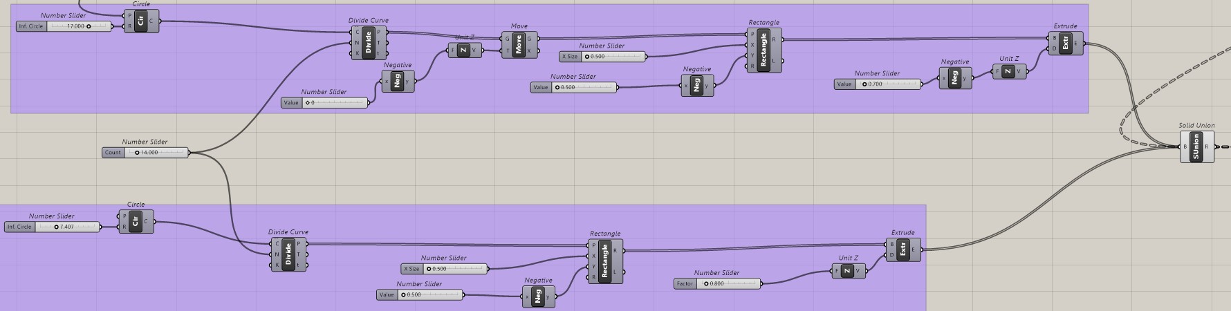
Create the connections between the foot elements and the trays. For this I opted for a mortise and tenon and therefore from the circles of the first step, create my tenons «rectangles» to extrude and assemble them to the elements of the foot from «solid union».

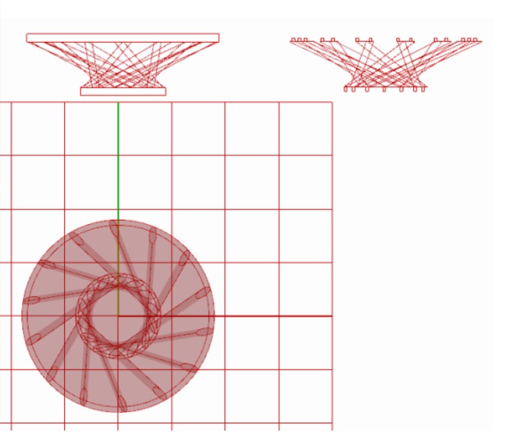
The 5th Step:
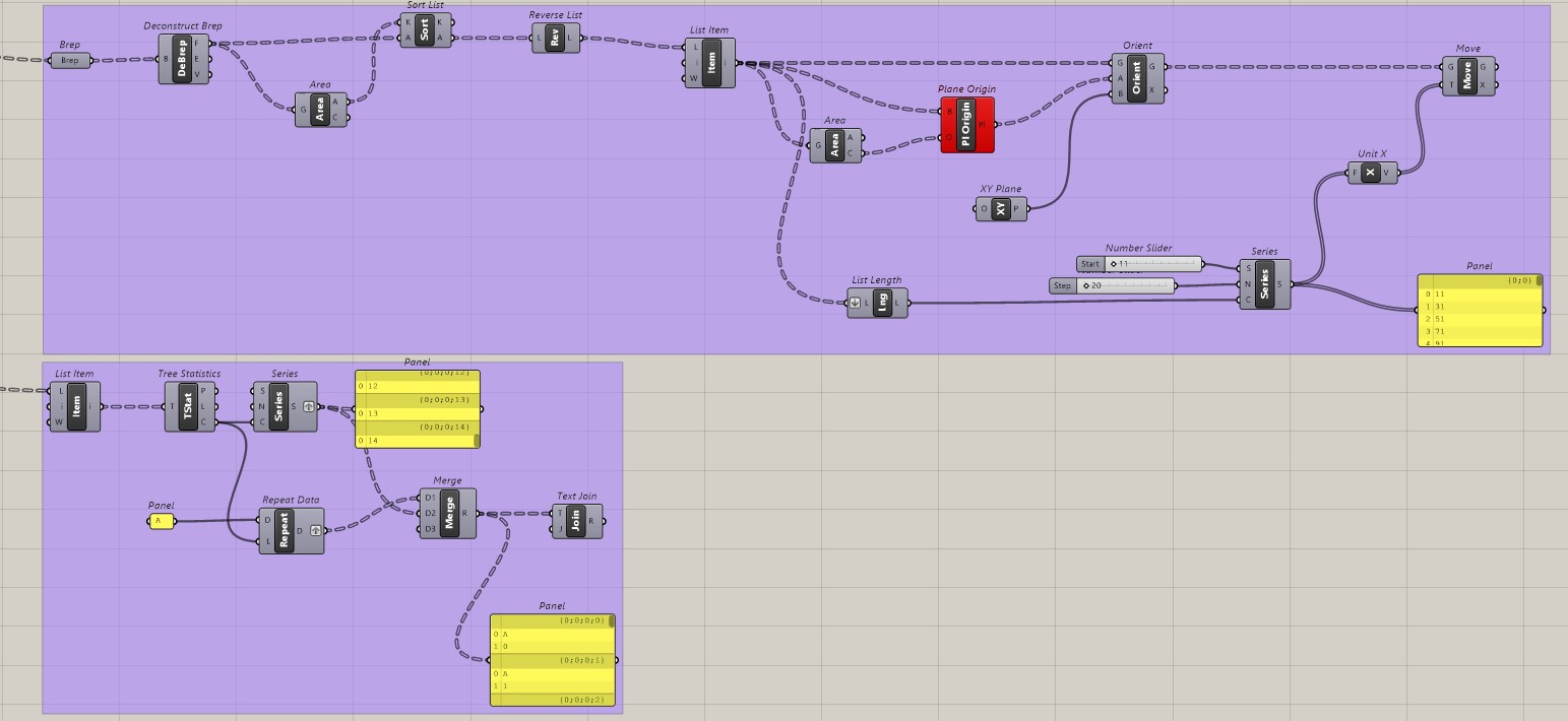
The creation of the patterns. For this I took the final geometry of the furniture to project a view of the elevation «Front» of the 3D image «Make2DRhinoView» in a 2D pattern «Make2D» and «Curve». Then you have to place this pattern in the whole view «Move» and «Amplitude» to finally join the lines together «Join Curves».
The same thing will be done for an elevation view of the foot elements.

Improvement:
For more precision, it would be necessary to be able to project the elements individually and to name them. I tried to do this by breaking down the surfaces and dividing each «item» composing the foot and then projecting it in 2D. Then, by dividing each item, to create a series that would allow me to assign them a number in a logical construction order. But the data of their original plan shows a dysfunction on this system.