
Design computing 555DC3 ws24
Simon Stråle

Background
Arches are commonly found in historical grand architecture due to its ability to transfer loads to specific points, allowing buildings to have large open rooms and openings in the walls. Today we have technology and materials that can take both compression and stress. This give the Architect the opportunity to create simpler orthogonal loadbearing systems while the art of designing through structural geometry has been lost. Designing compression only systems reduces the total amount of stress in the system, allowing for thinner constructions and thus reducing the amount of material required. Alternatively, it allows for new more sustainable building materials to be developed as they don’t require the same stress resilience as in conventional buildings.
Using modern computational software, we are no longer restricted to domes and vaults for compression only structures. We can easily calculate the most efficient design of non-orthogonal geometry and quickly try different iterations during the design process.
Historical applications
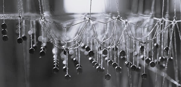
The principle behind the method is simple and was used long before the use of computers. It is based on the fact that a flexible line, such as a string or a chain hanging will create the inverted shape of a rigid arch. Similarly, a hanging piece of cloth will create the inverted shape of a compression only structure with forces distributed three dimensionally.
“As Hangs the flexible chain, so but inverted will stand the rigid arch”
-Hooke 1676
Antoni Gaudi
In the design process of Sagrada Familia, Gaudi used this principle by constructing a model of the church using a system of hanging chains and weights
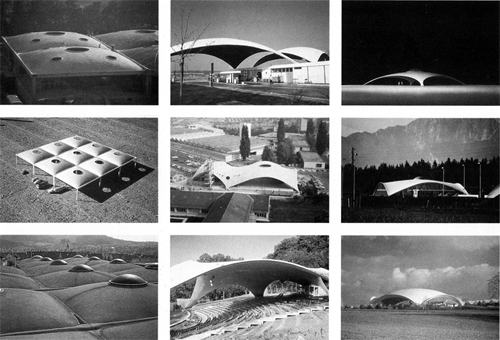
Heinz Isler
During his career, Swiss engineer Hynes designed and built aver 1000 shell structures. Many using experimental approaches but some of them for actual buildings. His design process often included hanging a wet cloth from anchor points, freezing it and then flipping it upside down.
Modern applications
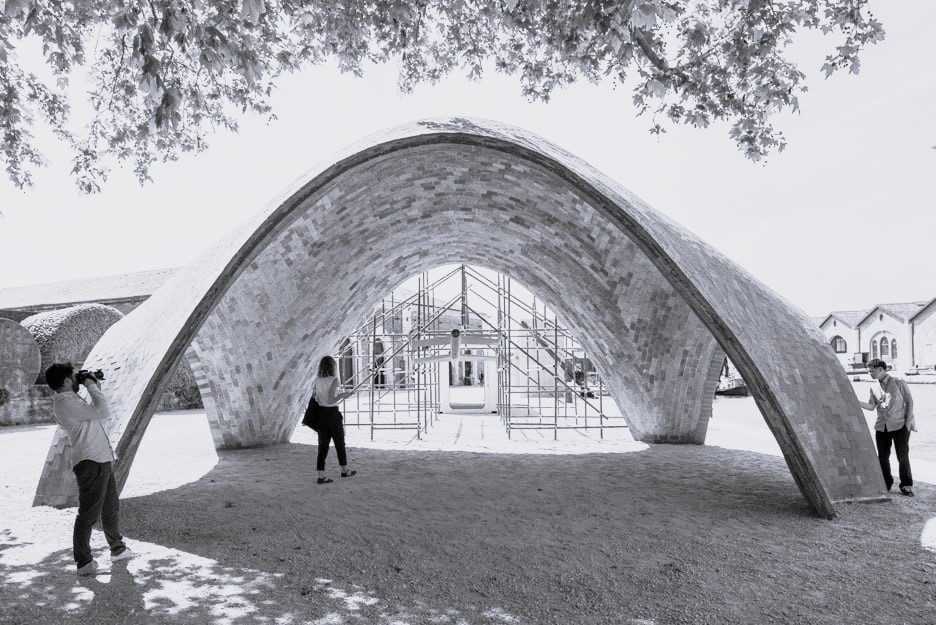
Drone Port
Drone port is a project developed to function as a hub for drones to be able to deliver urgent medical supplies to remote and inaccessible areas in Africa. The design was created by Norman Foster and a full-scale prototype of it was erected for the 2016 Venice Architecture Biennale. It is constructed with a brick of compressed earth called Durabrick, developed be possible to cheaply be created in poorer parts of the world
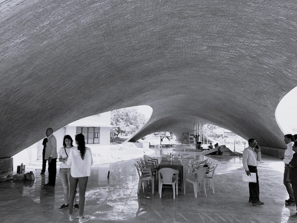
Maya Somaiya Library
Architecture studio Sameep Padora & associates designed an addition of a children’s library on a narrow site of an existing school. The inspiration for the form came from wanting to keep the outdoor space for students to play. The vaulted ceiling allowed inspiring spaces to be formed on the interior while the roof can act as an extension to the outdoor area.
To design the building the Rhino extension RhinoVault was used. This is a program that calculates compression and tension stress in a system, made to calculate complex vaults. It is constructed using the 16th century method of Catalan vaults. Using thin bricks of alternating orientation with a thick layer of mortar in between, allowing the construction to bend in different axis.
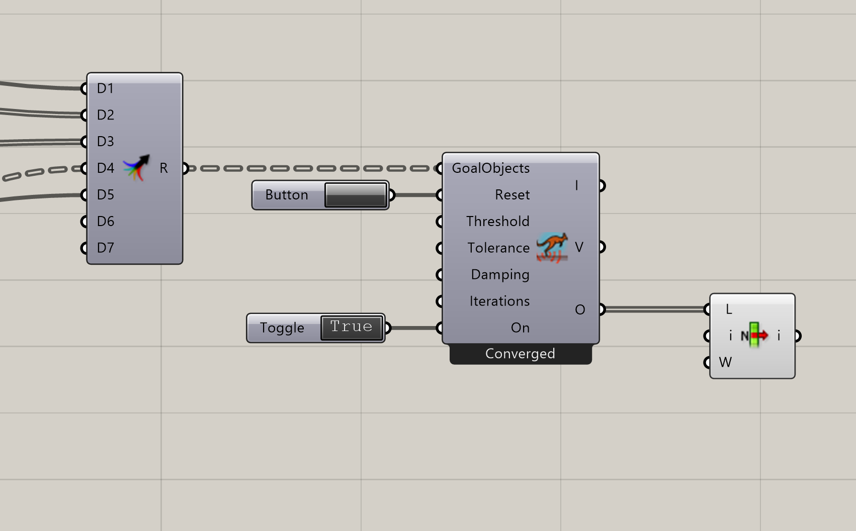
Kangaroo
Kangaroo is a plug-in for grasshopper that now comes included with the latest versions of Rhino. The function is used to simulate physics of an object based on goal objects that are defined by other parameters. It can for example be used to simulate collisions of shapes or volumes, beams and breaking points, folding geometry, or bending of geometry as this project will be focused on.
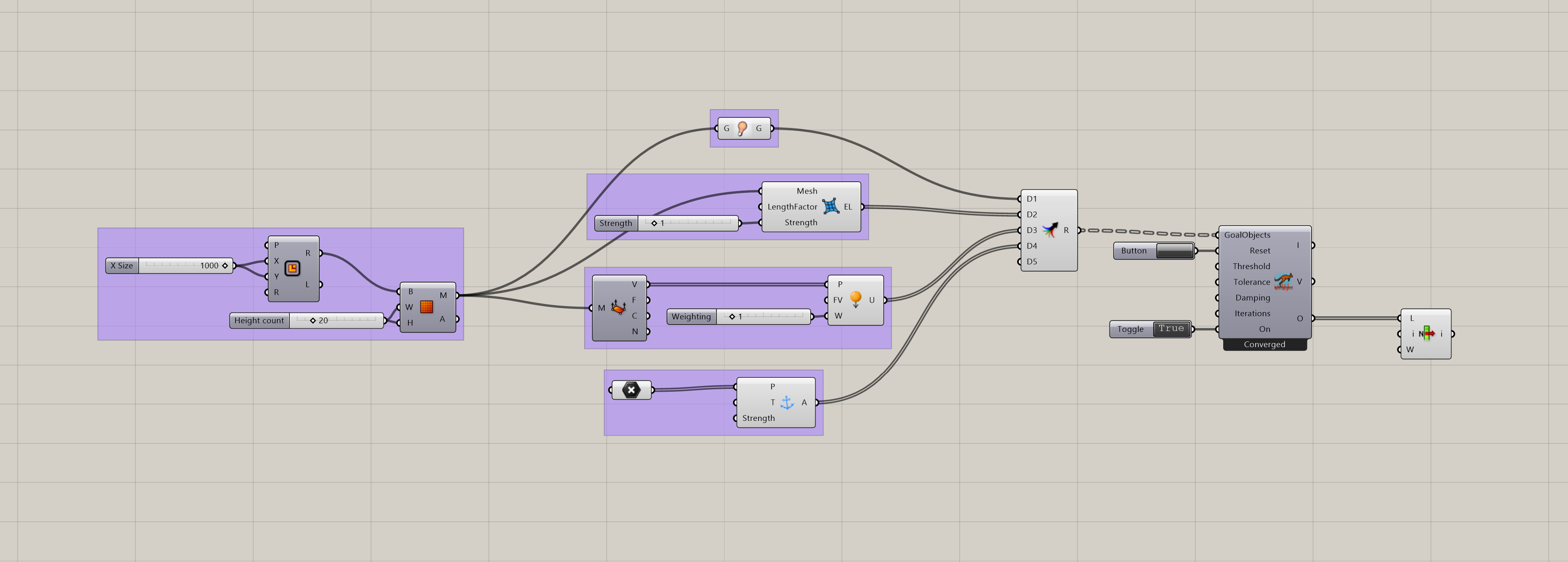
The basic Parameters
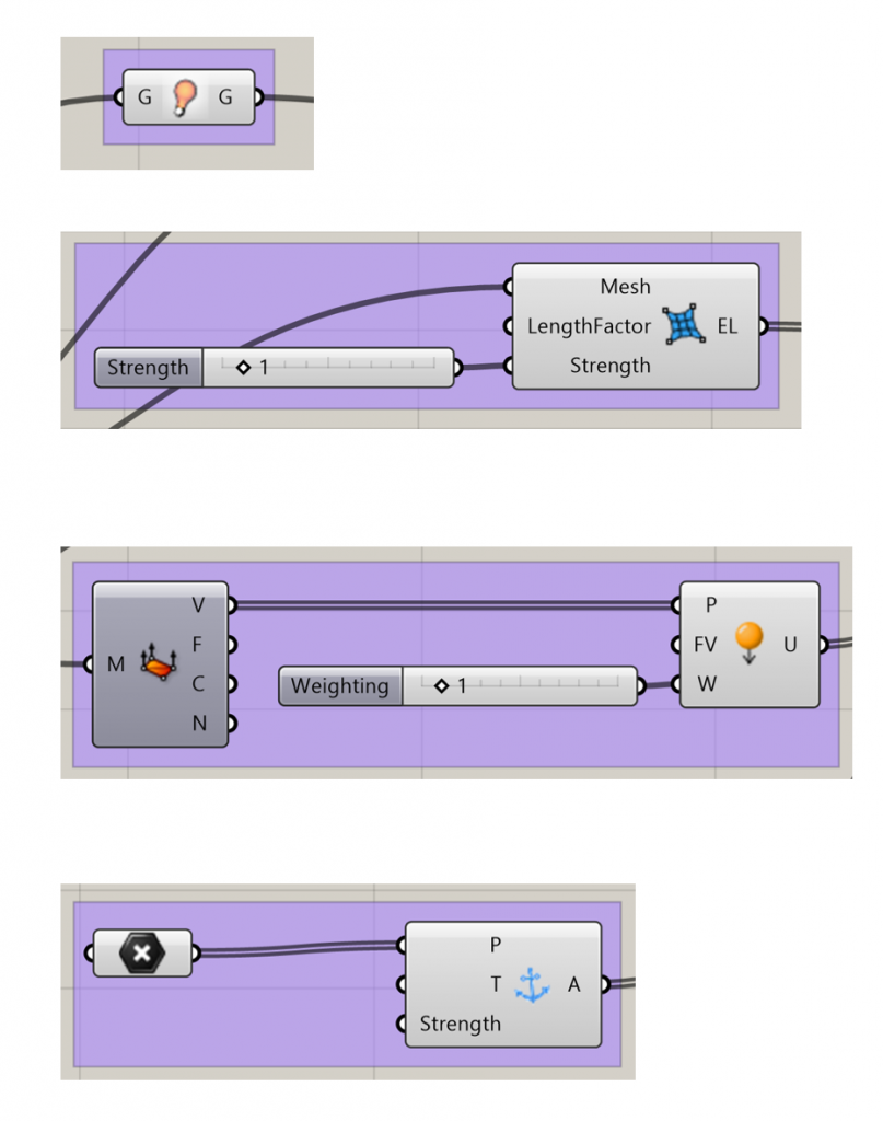
Show – Show the result.
Edge Lengths – Makes the vertices of a mesh flexible and specifies their target length as a factor of their current length.
Load – Put a load on the vertices to control the curvature of the arches.
Anchor – Specifies points on the mesh to be fixed in place. In the case of constructing compression only structures these are the points where the construction meets the ground
Creating a shell structure
The function requires a mesh. A square mesh can be simply made using mesh plane.
To achieve the organic building shape I imagined, an interpolated curve is made from inserted points. The curve is then converted to a polyline to simplify the triangulation. The line is then patched and then triangulated.
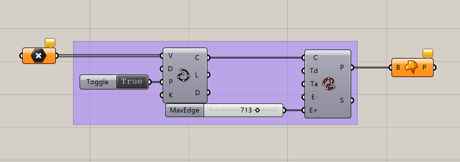
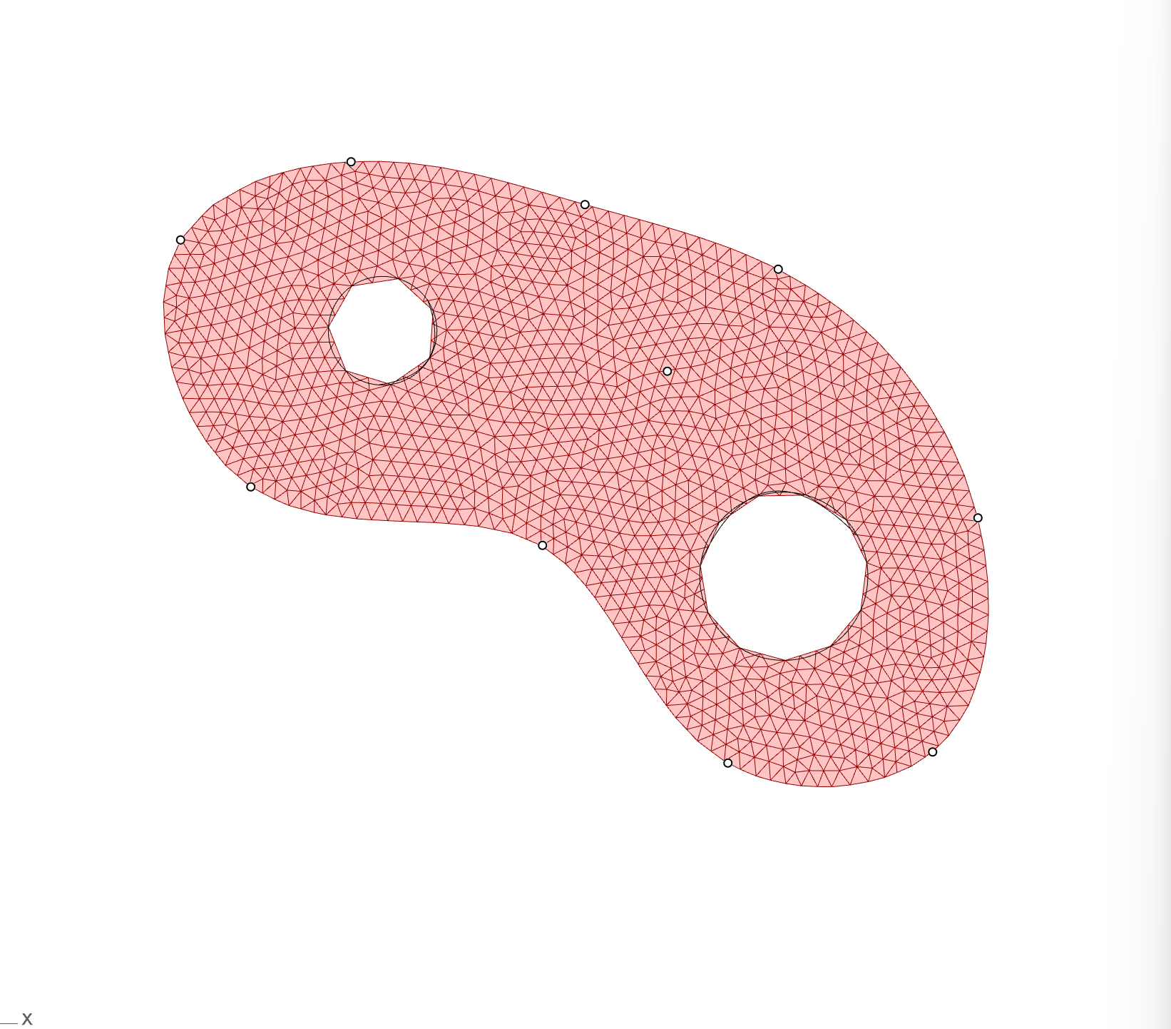
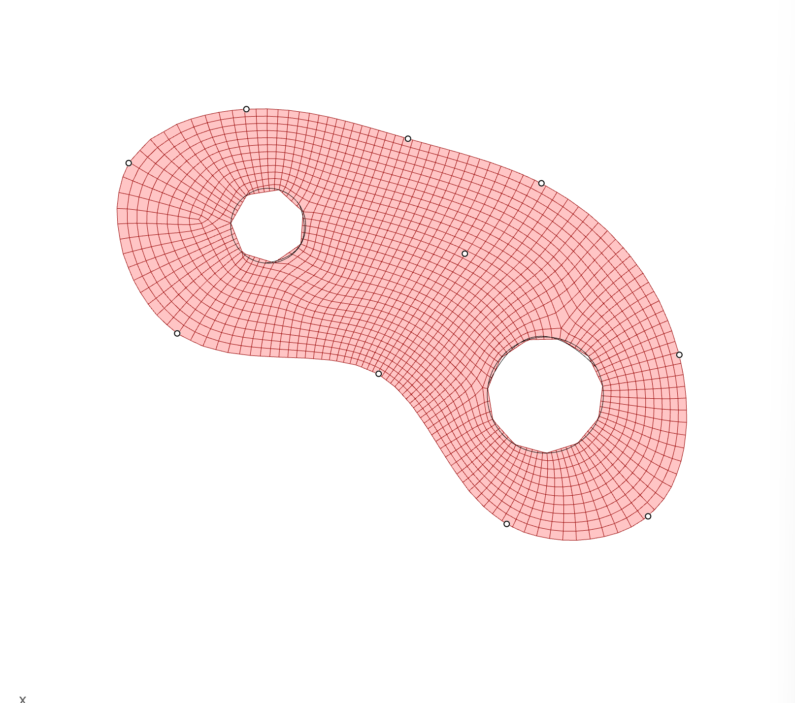
Cutting holes in the shape
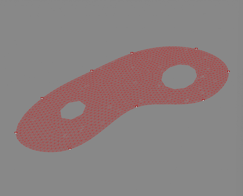
Curves can be drawn within the polyline and surface split creates a new surface with the curves subtracted.
The resulting surface is then triangulated to get a mesh with evenly distributed vertices.
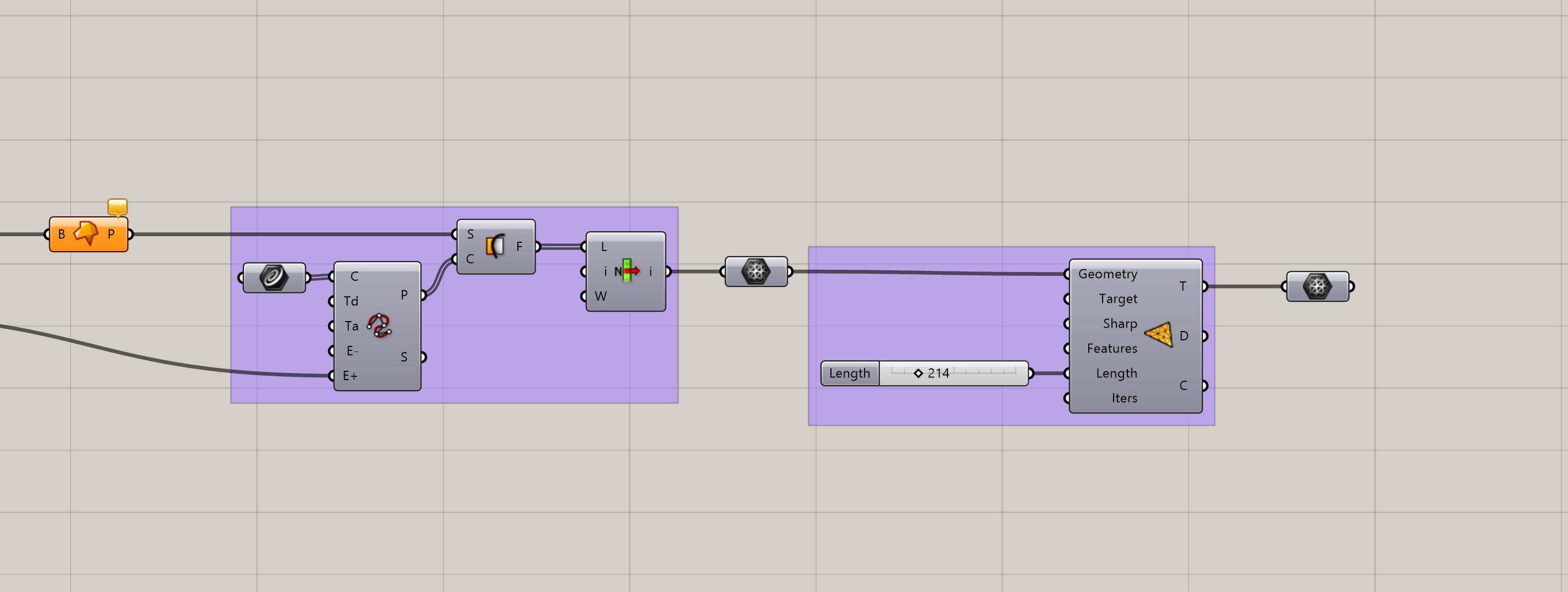
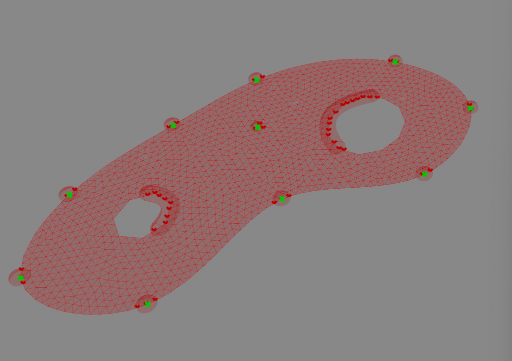
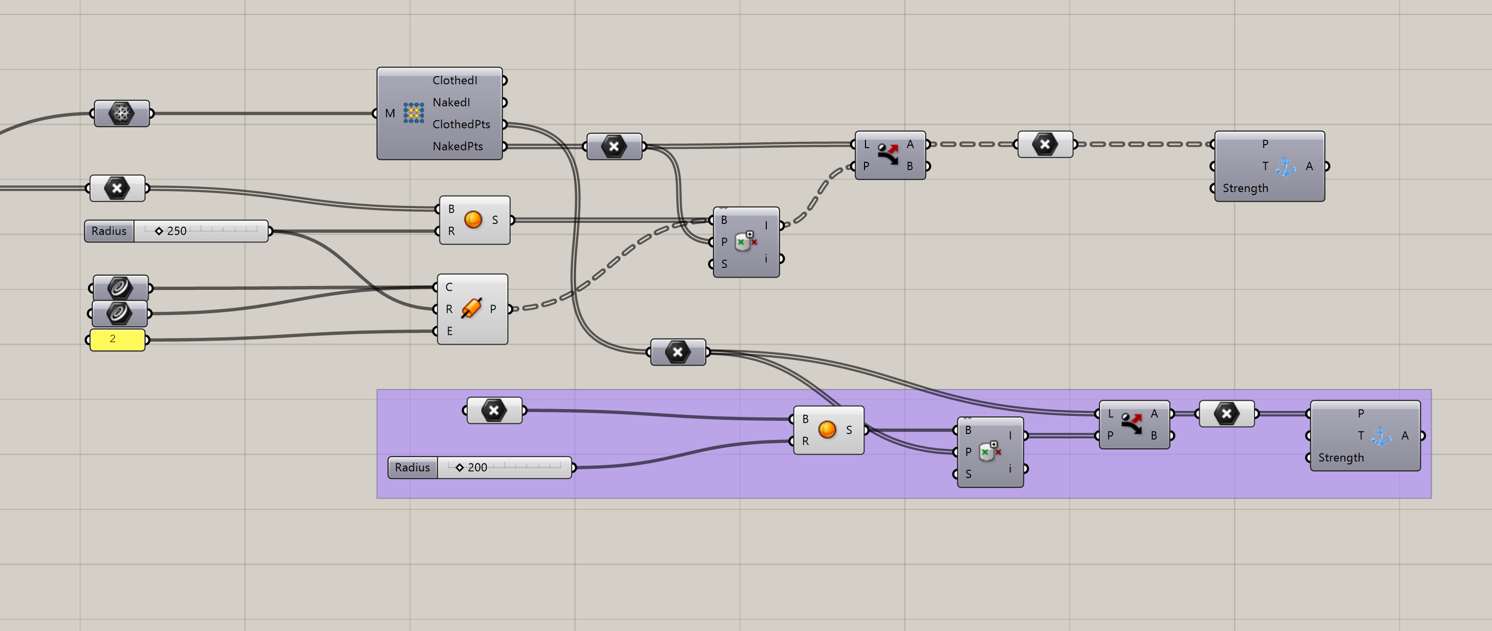
Creating the supports
Points on the mesh near the initial points need to be identified. Spheres are created on the initial points. Naked vertices separate the naked from clothed points. Points in Brep is used to check which naked points are within the desired radius of the initial points. These are then anchored in place. Entire walls going to the ground can be created in the same way but with pipes created from drawn curves along the wall. Additional supports can be created within the shape by placing points and testing for clothed points in the mesh.
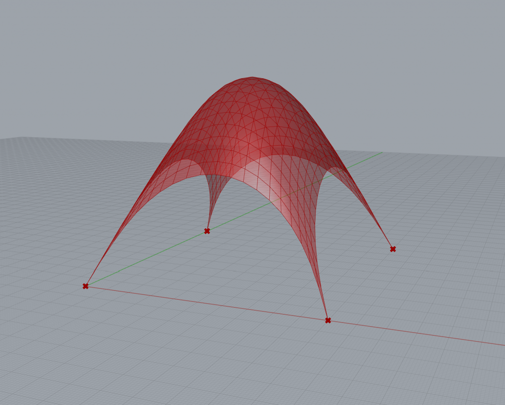
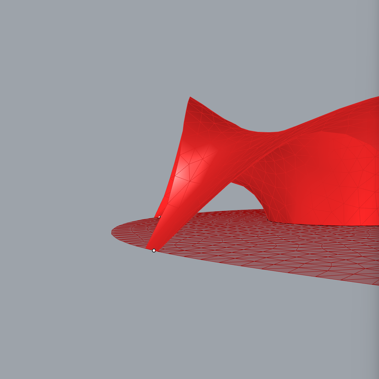
Running the Kangaroo simulation with the given parameters give you a geometrically structural shell. The height can be altered by changing values on the strength of edge length and the weight of the load.
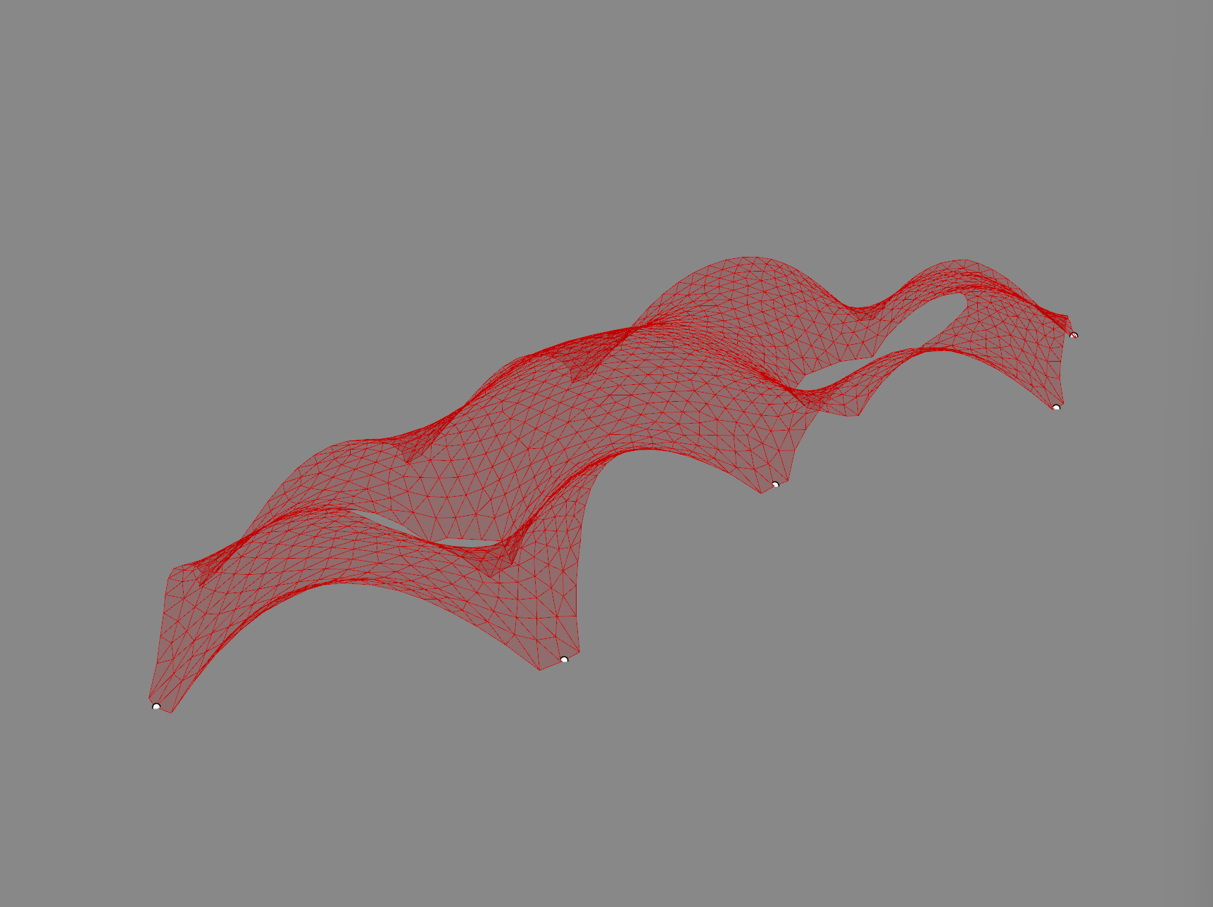
Comparing meshes
In the project I used Tri-remesh to create a triangulated mesh for the base shape. This aims to create close to equilateral triangles. I tried to use the Quad-remesh to create the mesh instead to compare the results.
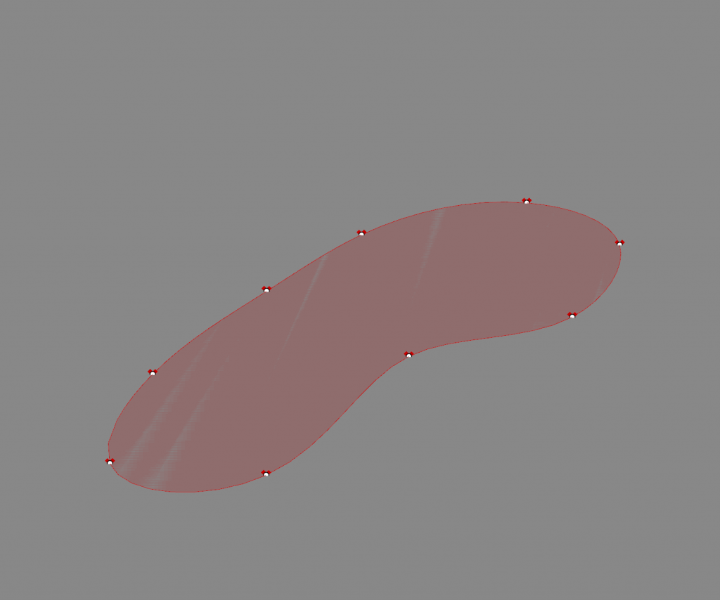
The red shape is made using tri-remesh and the blue using quad-remesh
In the result it is evident that the new shape differs from the original shape.
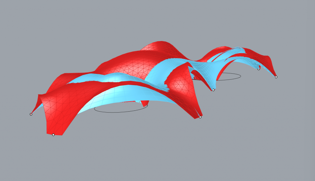
The quadmesh resulted in some uneven geometry. The reason for this is that quads have uneven sizes and sometimes meet at uneven angles causing creases in the simulated mesh.
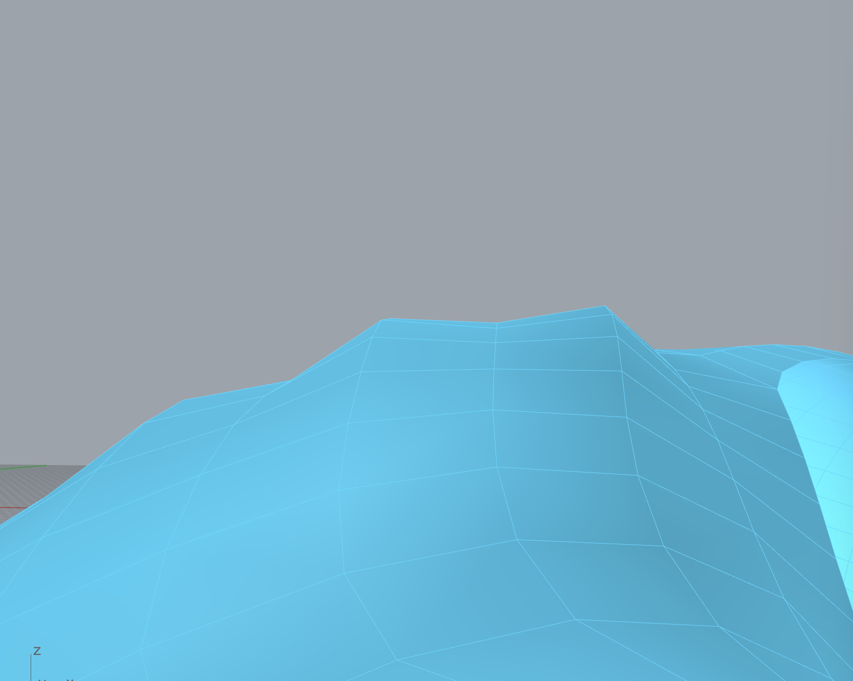
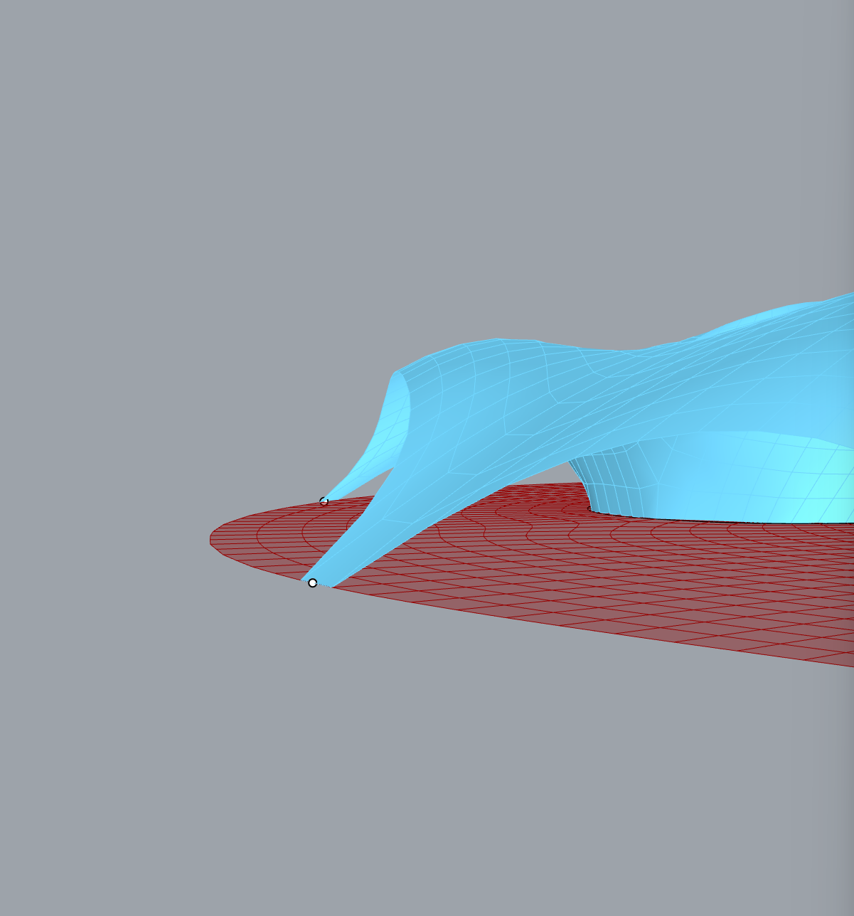
The difference is mostly noticeable on the open edges where the trimesh bends upwards whereas the quadmesh retains its form more. The reason is that the vertices are more evenly distributed in the triangulated mesh. The load function that act as vertical forces in this simulation acts on the individual vertices. In the quadmesh the density of the vertices is higher in the centre of a shape of this type than on the outside. This means that more vertical forces are acting on the centre than on the outside. To more accurately simulate gravitational forces a mesh with more evenly distributed vertices is desirable. Therefore when using base shapes with curvature, triangulation is the better method.
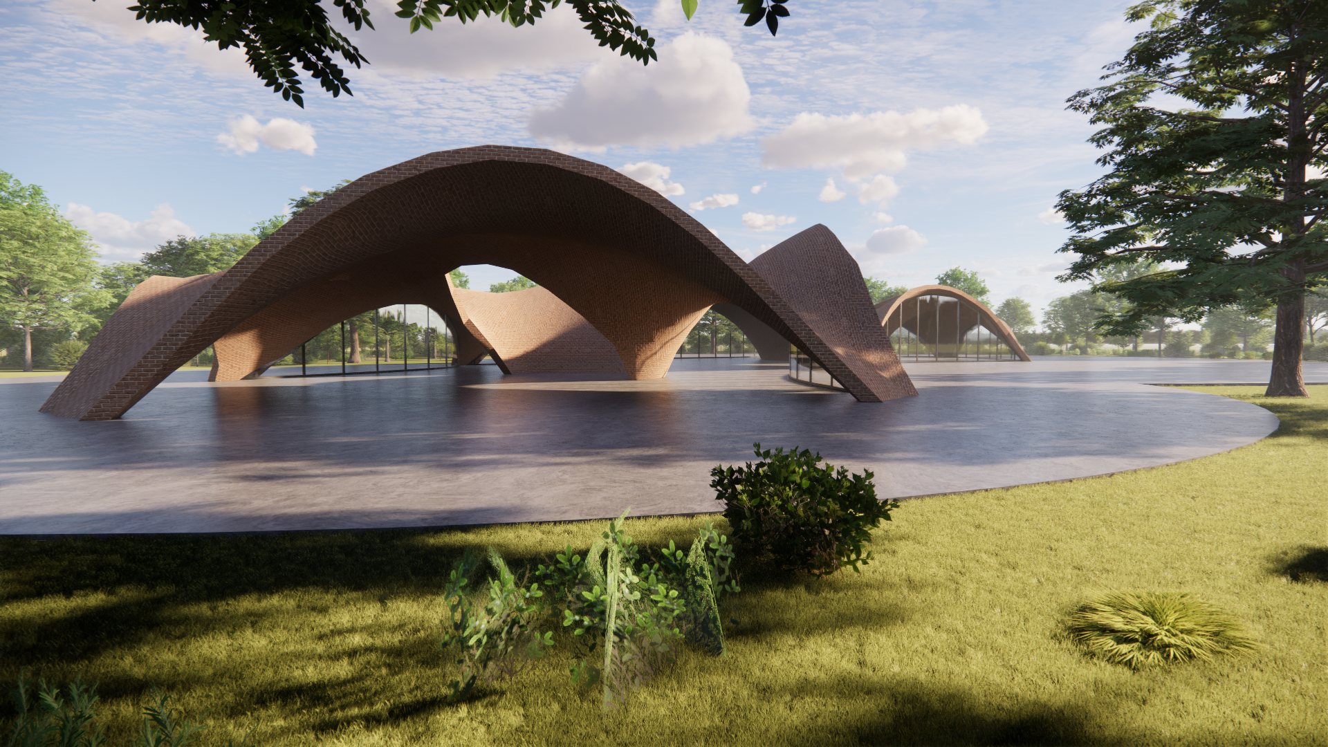
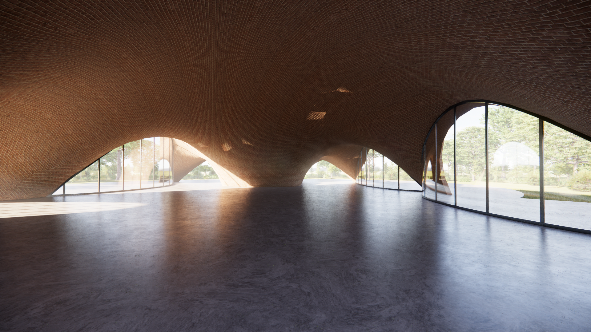
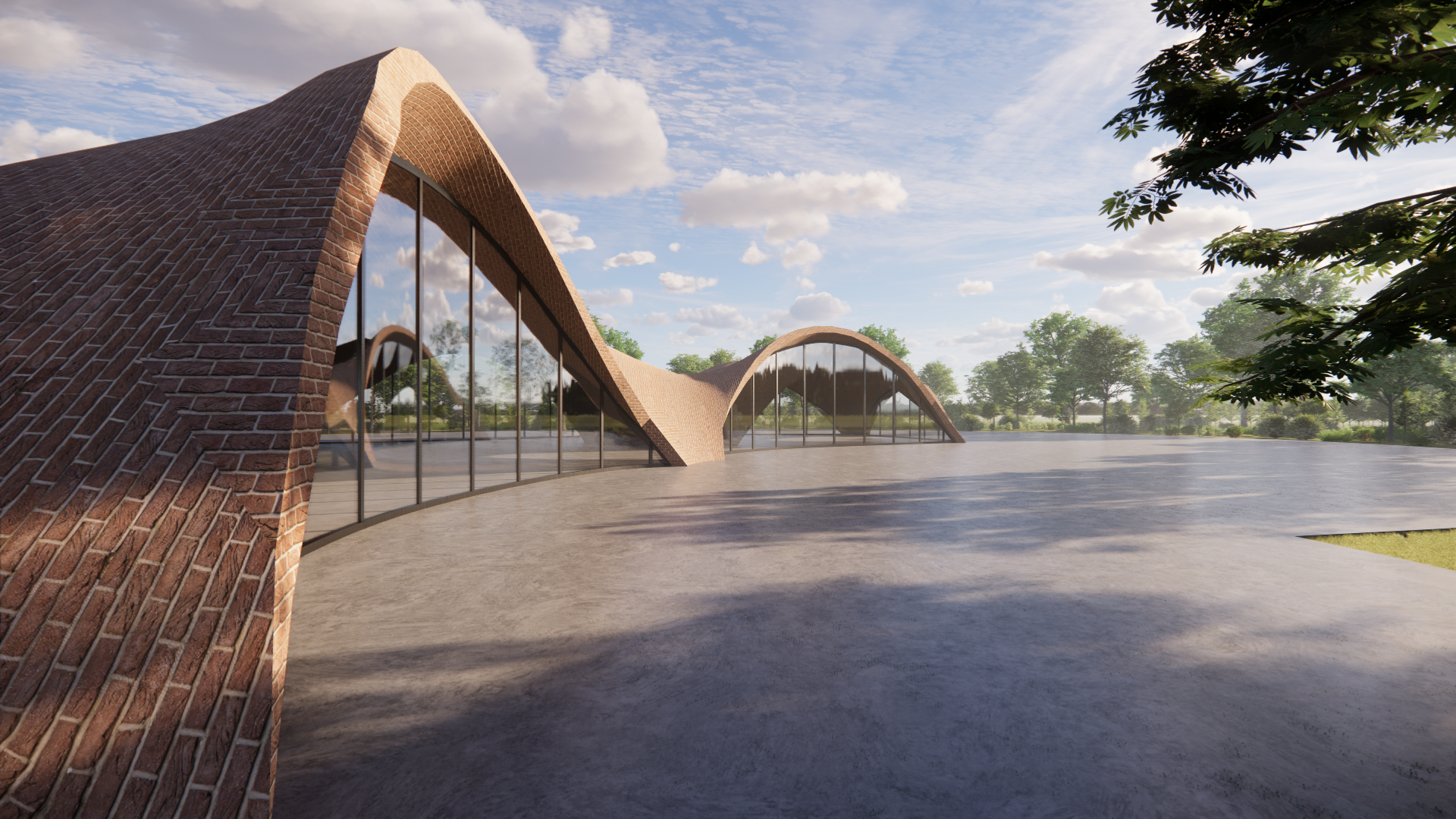
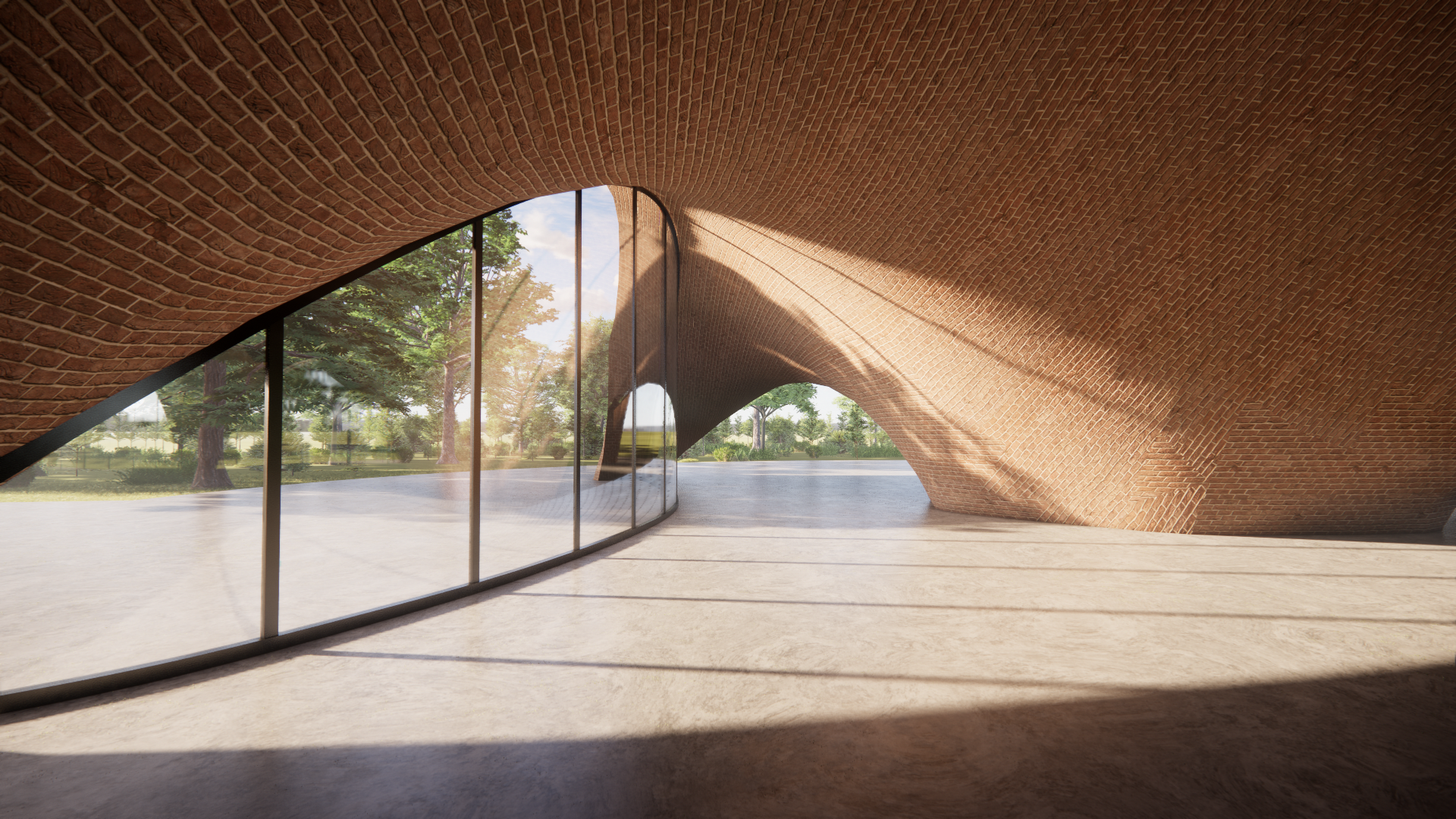
Applied renders
Sources
https://www.archdaily.com/903713/maya-somaiya-library-sharda-school-sameep-padora-and-associates
https://schwartz.arch.ethz.ch/Forschung/islerthemodelasaworkingmethod.php