GOAL I
The purpose of the tutorial is to provide a simplified explanation of how to create a parametric building with a supporting structure, a substructure and facade in Rhino7 and Grasshopper. The focus lies on the construction of the weather reactive facade and on how to bring all three elements together.
CONCEPT I
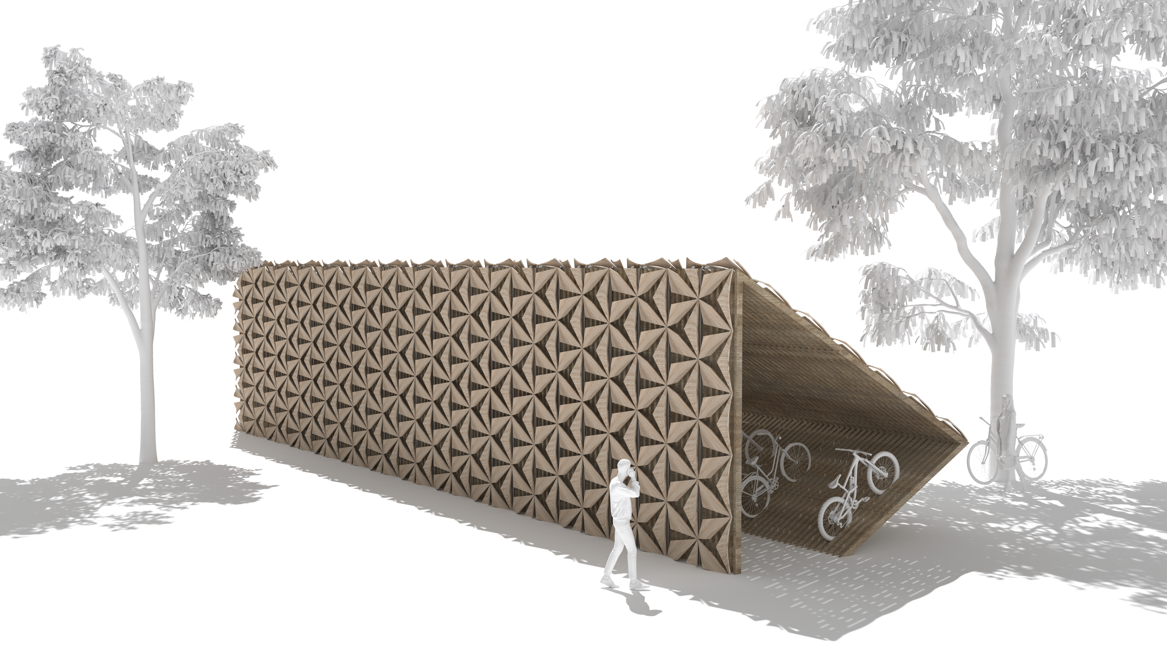
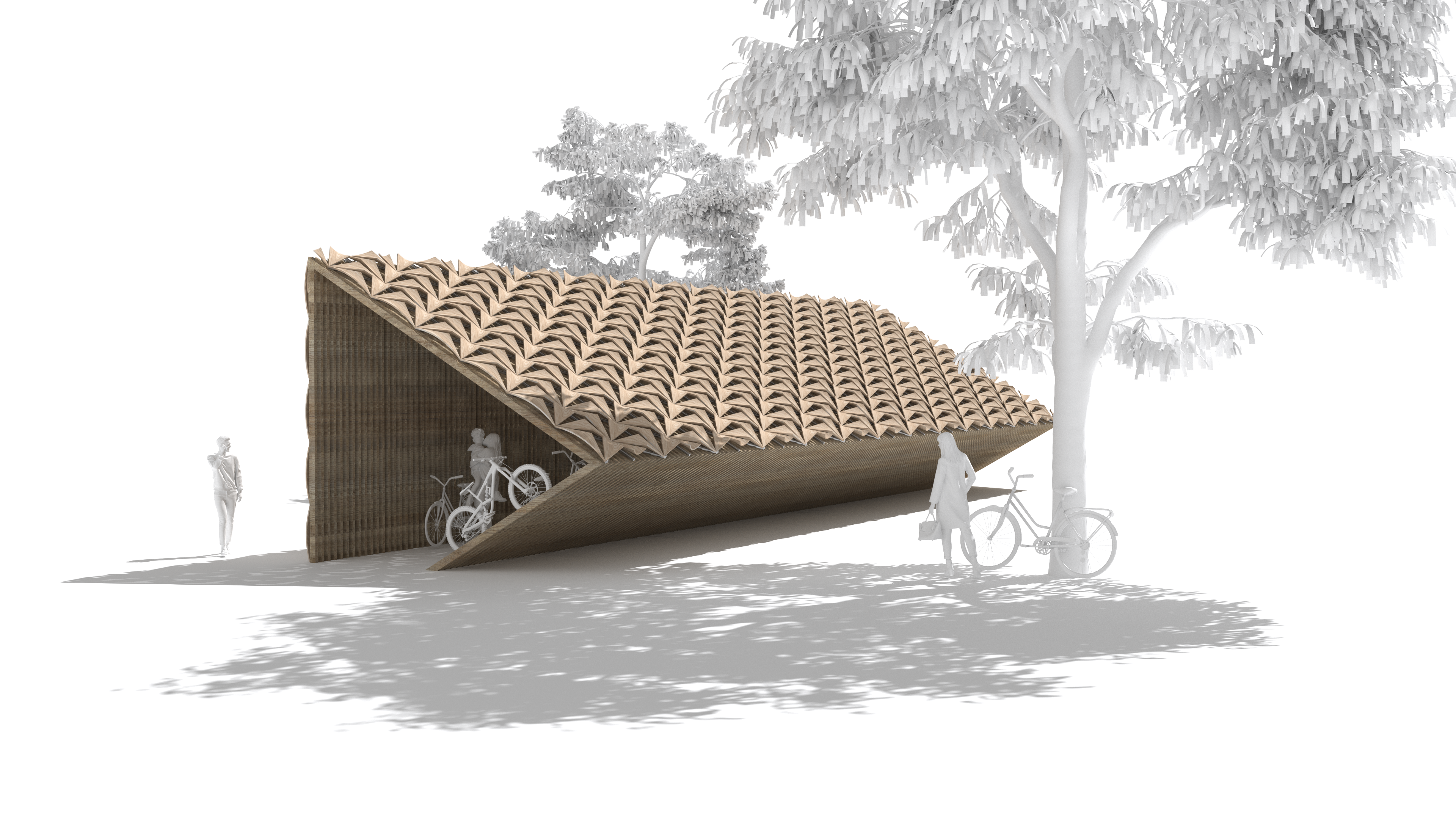
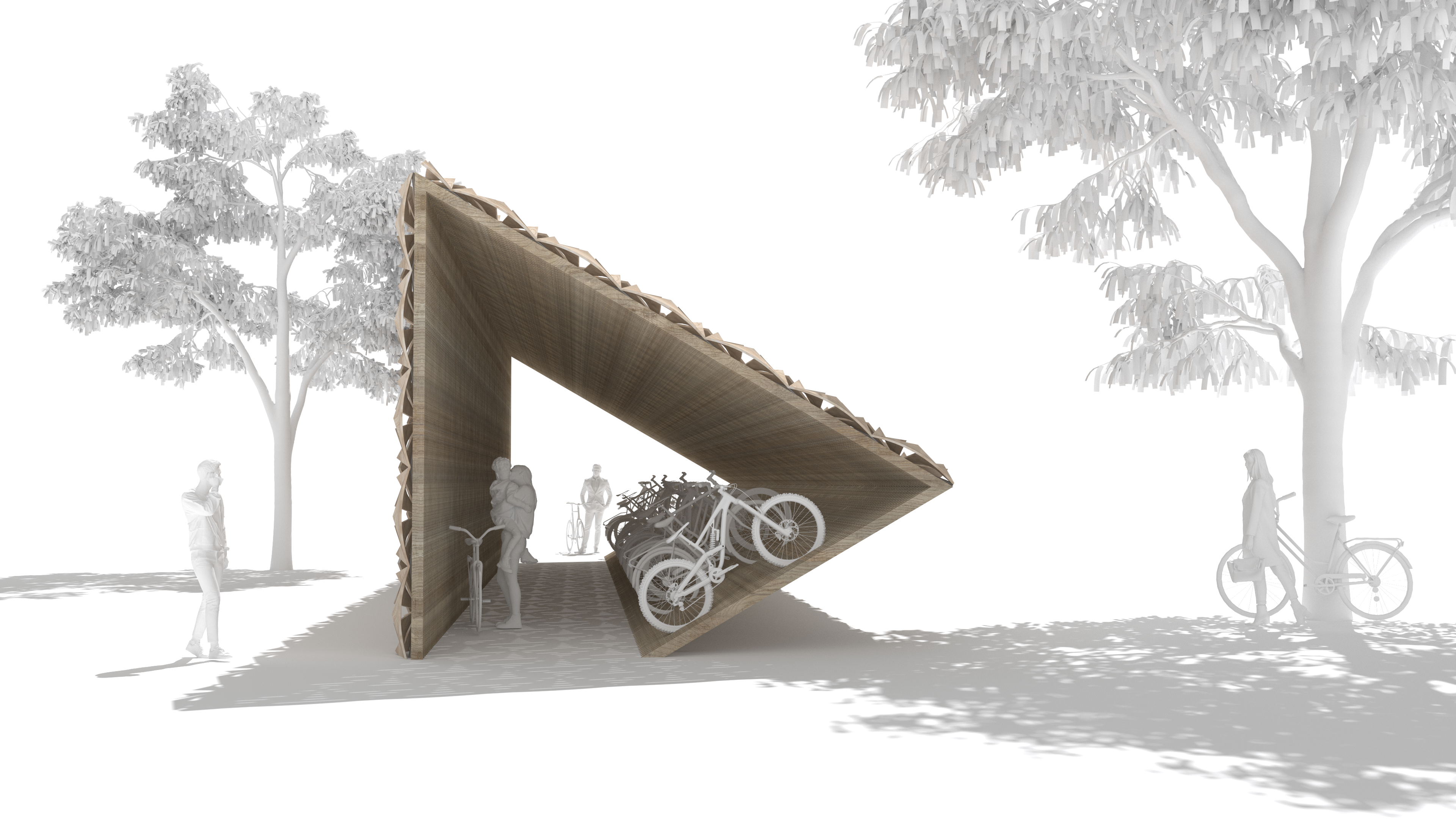
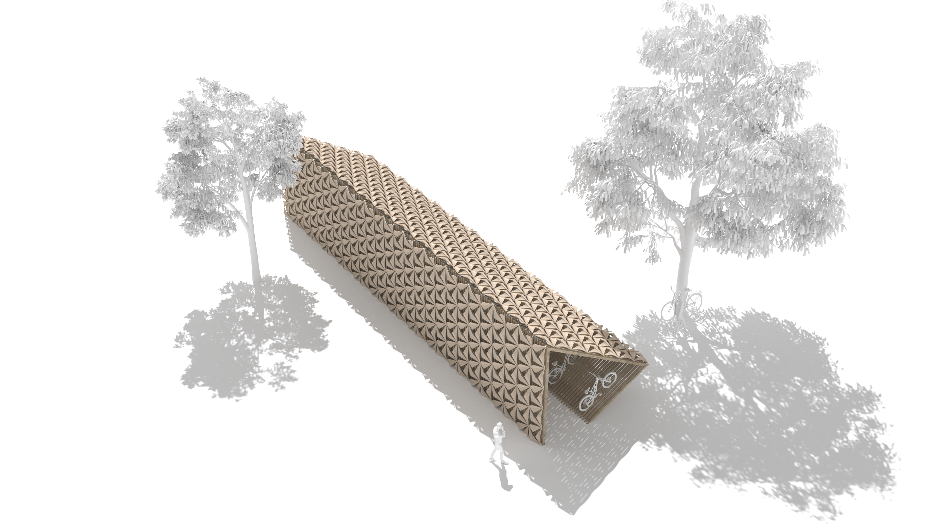
The mobility weather pavilion has the goal to provide a supporting structure that not only holds the facade but can also be used to park bicycles and therefore bringing change to a. The facade is the weather adaptive part of the pavilion and therefore closes and opens depending on the weather. It is inspired from nature and has the goal to protect the bicycles form rain and therefore from corrosion
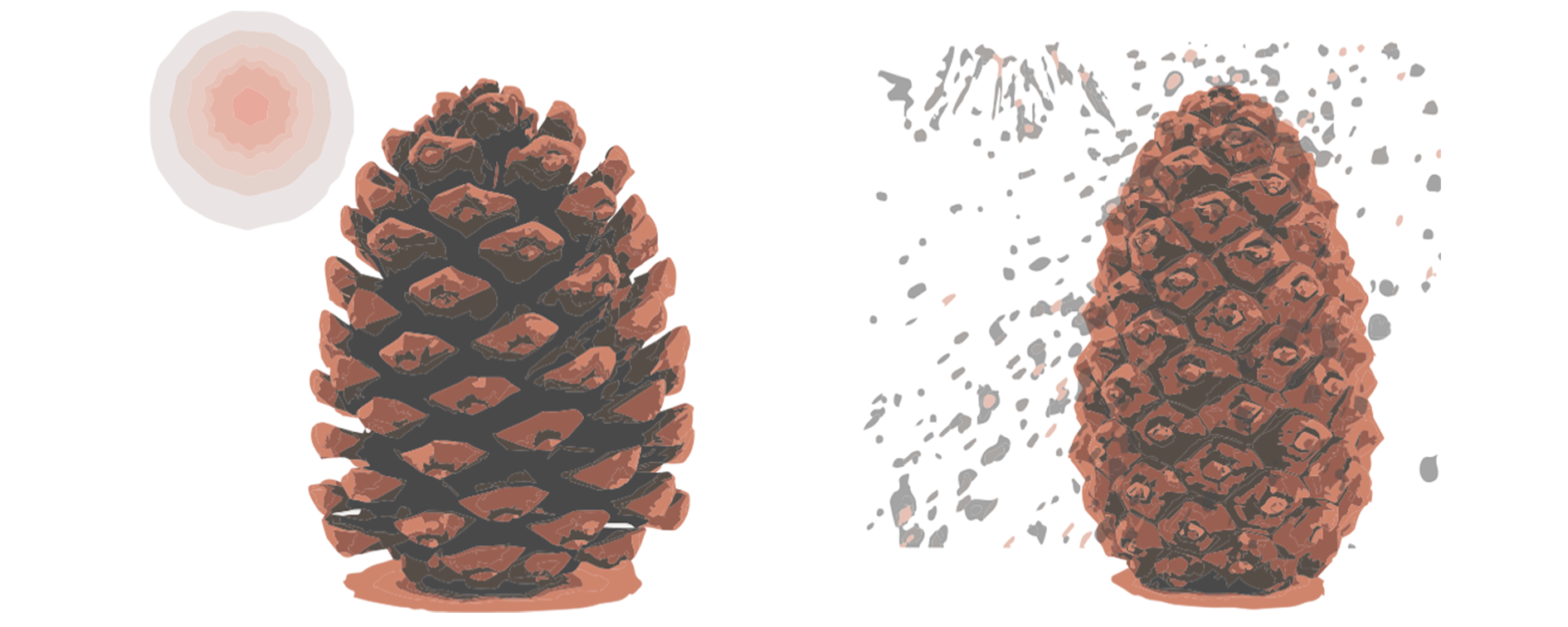
Example form nature: Pinecone
To mature, the seeds inside a pinecone need sunny, warm weather: when it is dry, the scales covering them are open and the seeds are exposed. On the other hand, when the humidity is high, the scales absorb water from the surrounding air. Their outside swells up; it expands and the cone closes: the seeds are protected from moisture and cold.
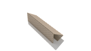
Example from nature: Wood
Wood warps, therefore, it bends when it dries and conversely flattens when it swells. This trait is currently considered more of a disadvantage, but recent research indicates that it can be used to our advantage in design of the facade.
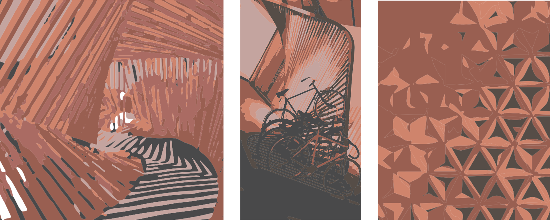
INSPIRATION I
The inspiration for the form developed of three images. The Ekko installation by Thilo Frank gave the input to create an architecture that you could walk through. Using this form for parking bicycles came from the image of parking bicycles in and semi vertical structure. And the last inspiration for the facade was climate adaptive surface by Chao Chen, which helped me find the form of my facade elements.
FULL SKRIPT I
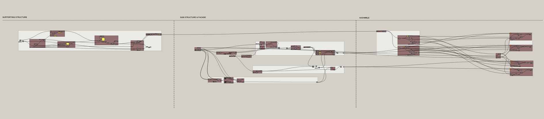
STEPS I
1.SUPPORTING STRUCTURE
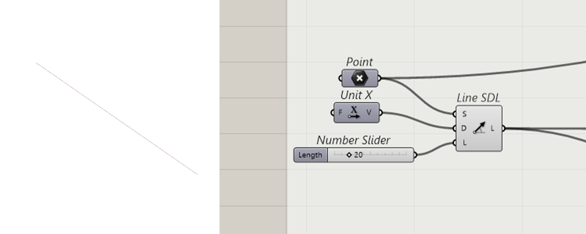
Step 1.1: Create line, that determines the length of your structure.
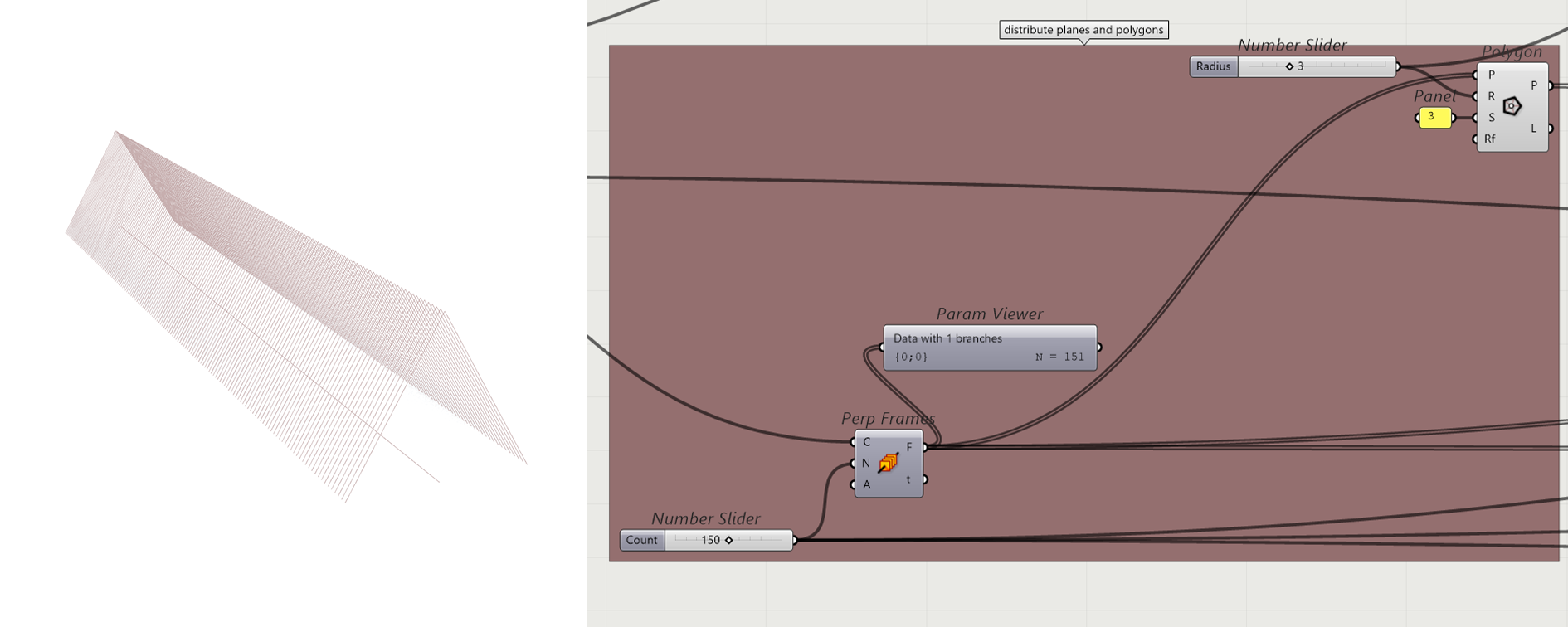
Step 1.2: Create multiple planes along the line by using the Perp Frames component, so that the Polygons are distributed along those planes.
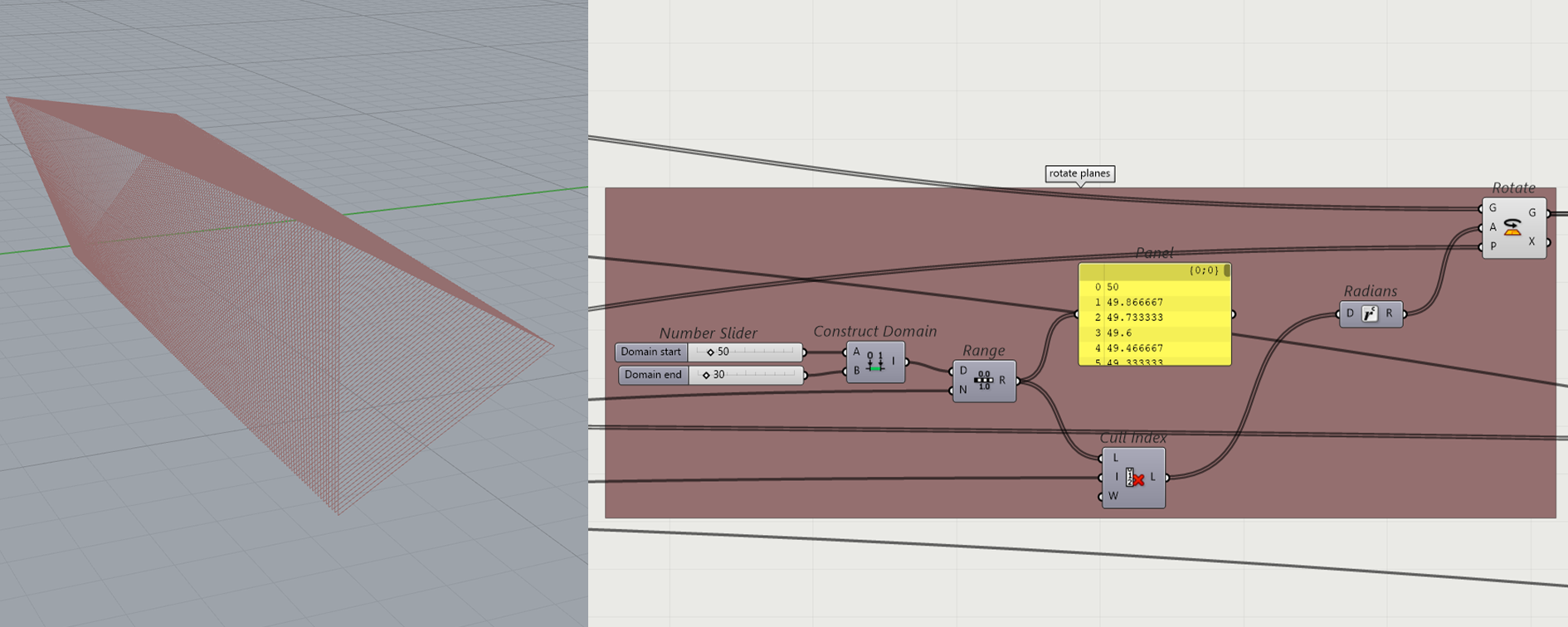
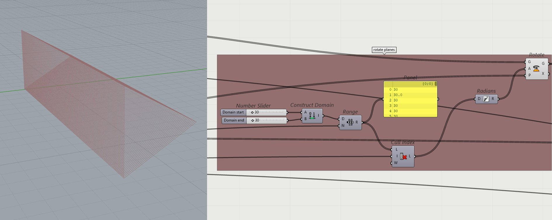
Step 1.3: Rotate the planes, by constructing a domain with values from 0 to 360. By using the range component, we get outputs that match the values from A to B to the number of frames evenly. Use the Rotate component to rotate the planes according to our number sliders of the domain. That allows us to create a twisted appearance. Because of the need to have a plane surface for the facade, the input of A and B need to have the same value.
Step 1.4: Create a new ground plane that is placed according to the dimensions of the polygon.
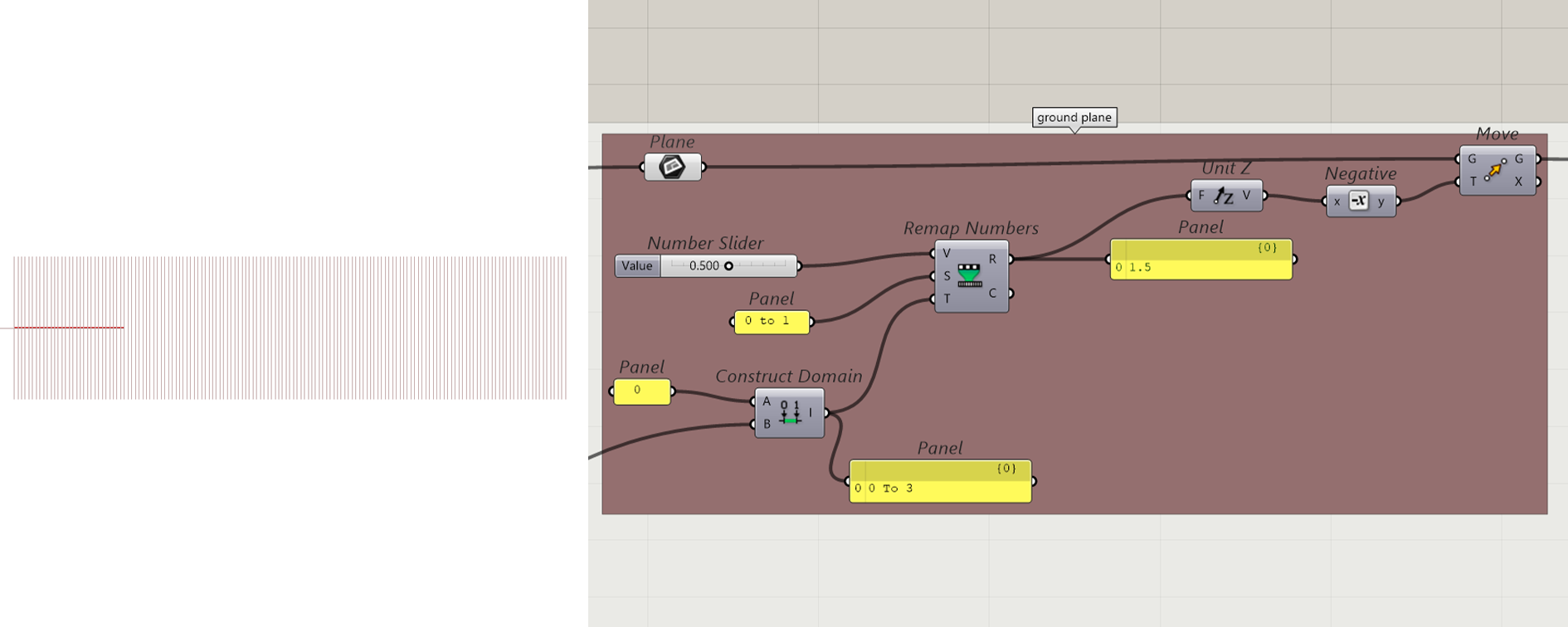
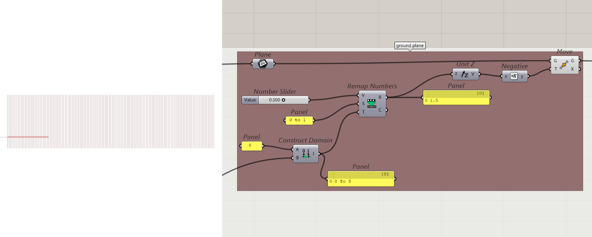
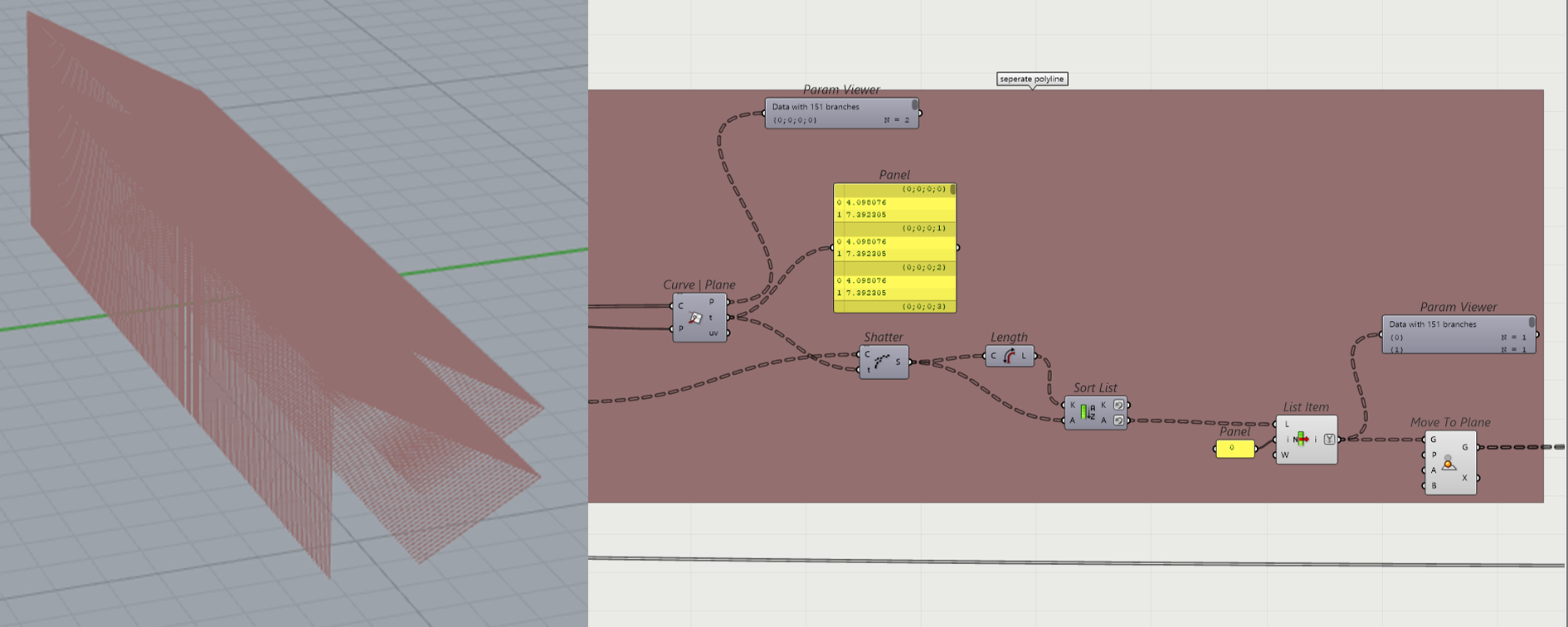
Step 1.5: Select the points between the newly constructed plane and curves. Shatter the polyline at the place of the points and sort the curves based on their length. With list Item select only the larger curves we want to keep.
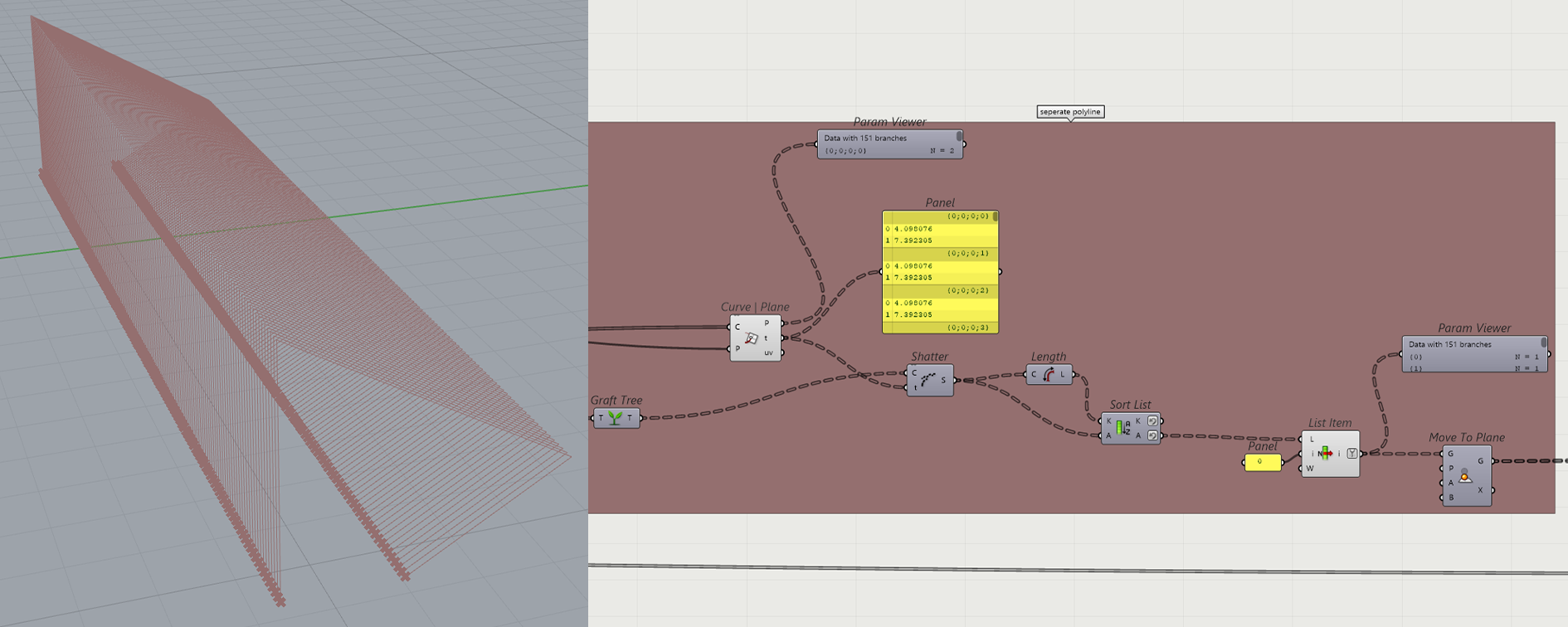
Step 1.6: Move the new curves to the ground plane.
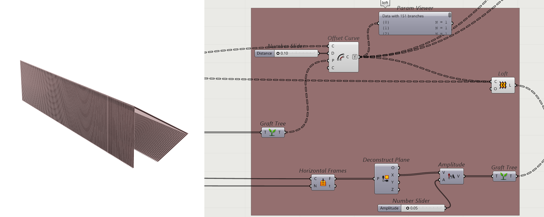
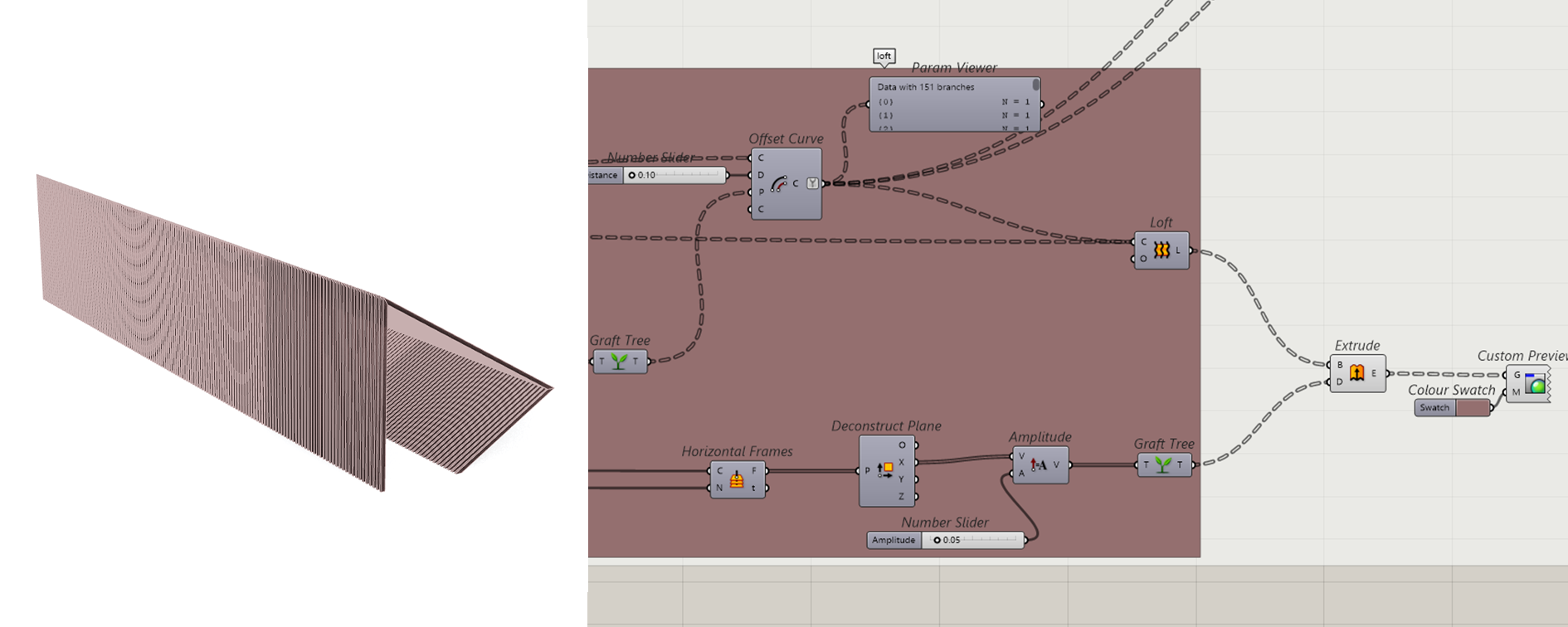
Step 1.7: Offset the curve and then Loft them. Extrude the newly created surfaces.
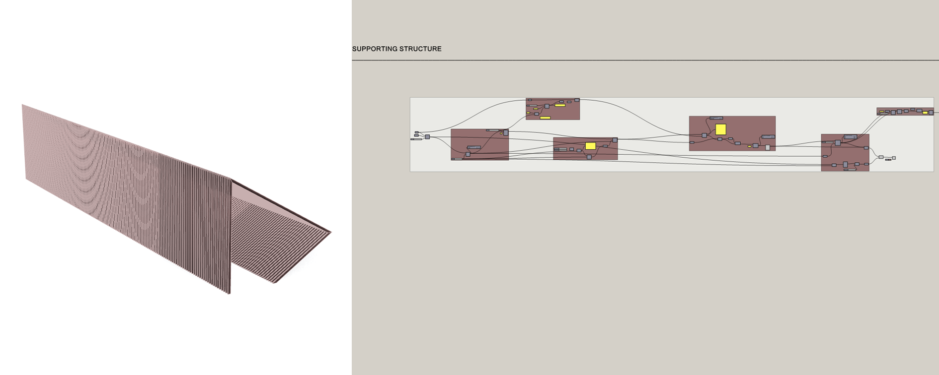
Full script for the supporting structure:
2. SUB STRUCTURE & FACADE
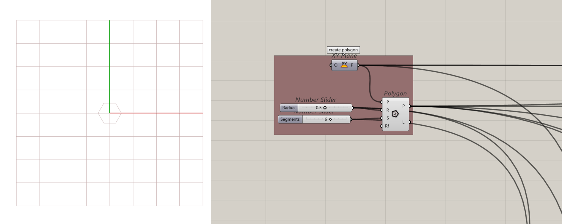
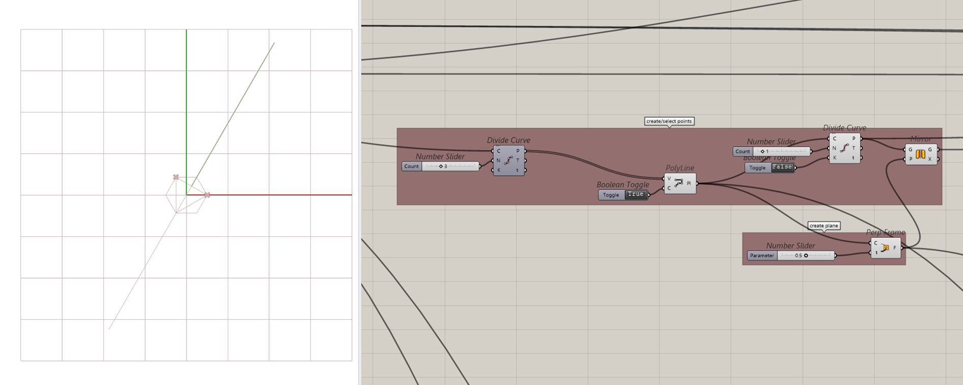
Step 2.1: Create Polygon, that is the base element to create the sub structure and the facade
Step 2.2: Divide the curve into three segments and create a rectangular polyline. Select two corner points on that polyline.
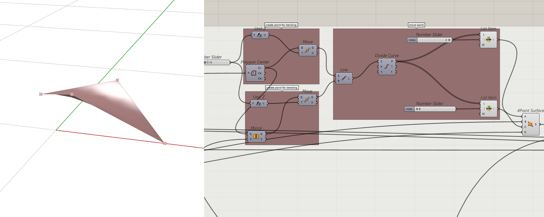
Step 2.3: The surface of a rhombus is created by four points. Two of the points are selected in step 2.2, the other is the center of the Polygon and the last one completing the rhombus is on the corner of the Polygon. The two newly selected points are moved to create bended surface.
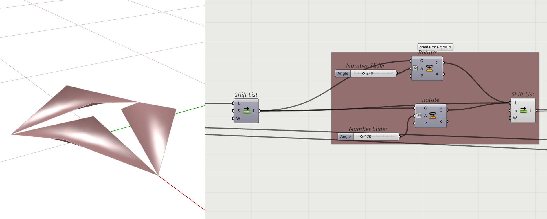
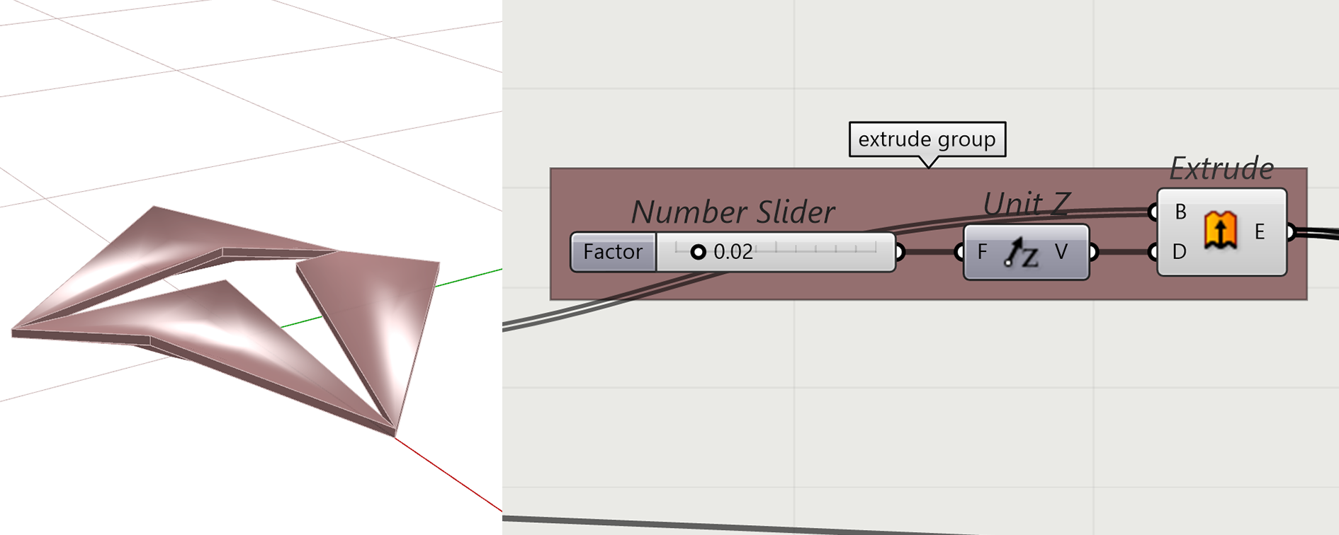
Step 2.4: Rotating the surfaces creates a group of three rhombus creating a hexagon. To create a volume the surfaces are extruded.
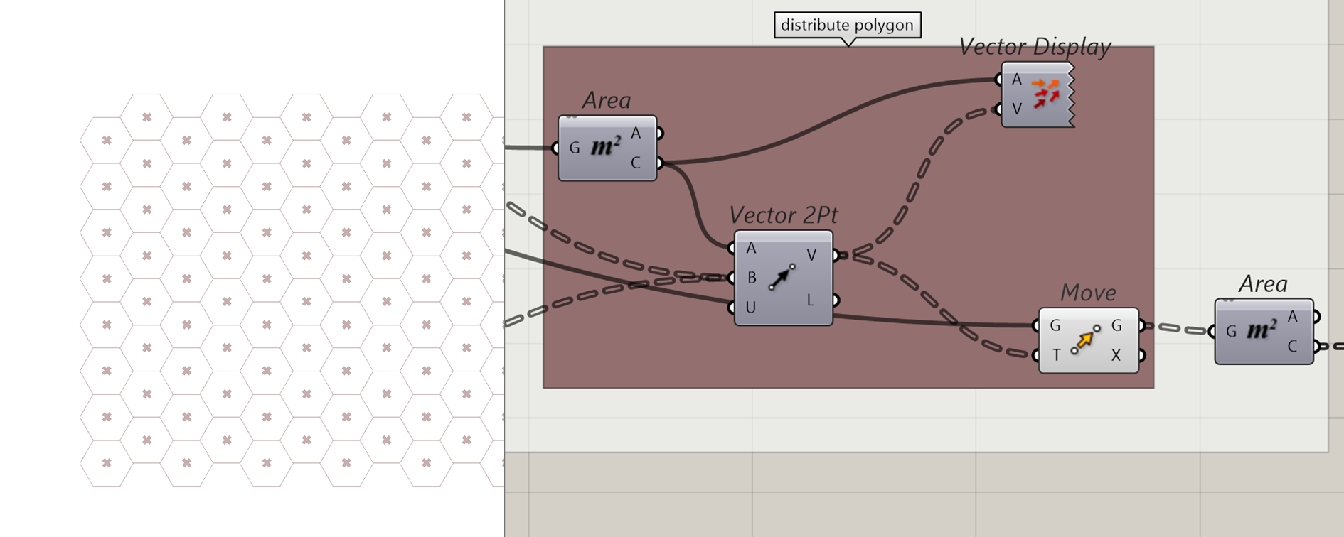
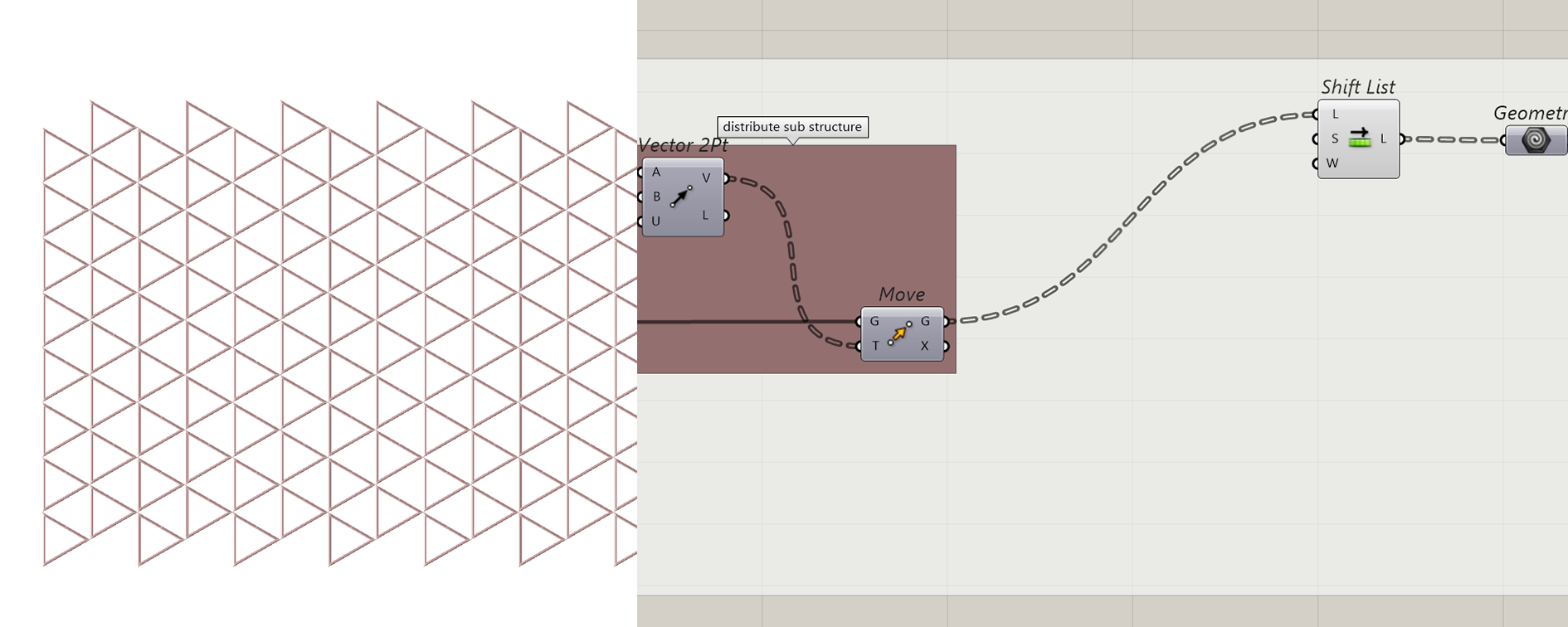
Step 2.5: To create a facade the group must be distributed in a pattern. The first step is to select the elements of the group with list item and then move them. We create a vector between two points to define the vector.
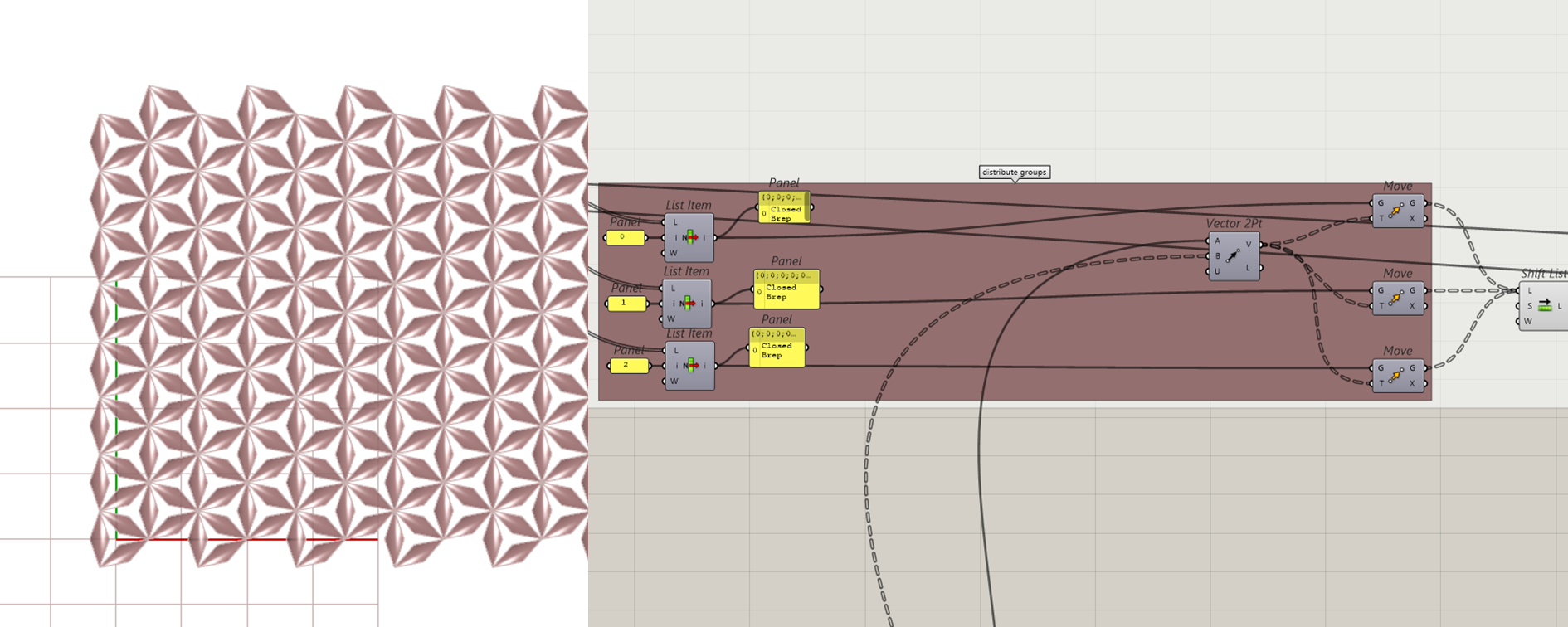
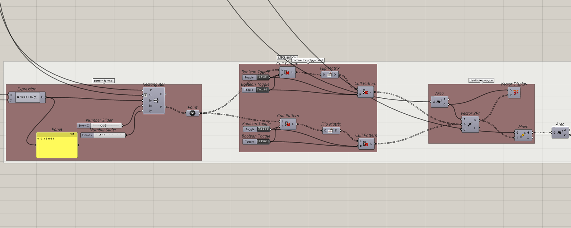
The input for Point A is the centre of one group item (meaning a group of the sub structure and the facade element). The input for Point B is created by a rectangular grid that is adjusted to the hexagon dimensions, with the help of an expression.
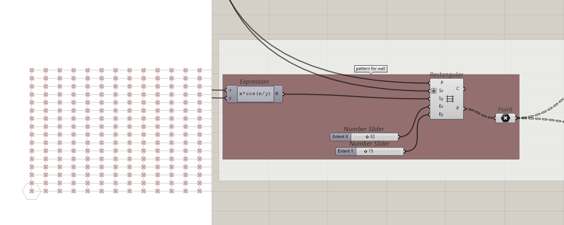
Out of this gid points are extracted and with the component Cull Pattern those points are selected in a pattern. For the distribution of the hexagons to work in both directions, the matrix has to be flipped. The input of the Point B is going to be the center points of the newly distributed hexagons.
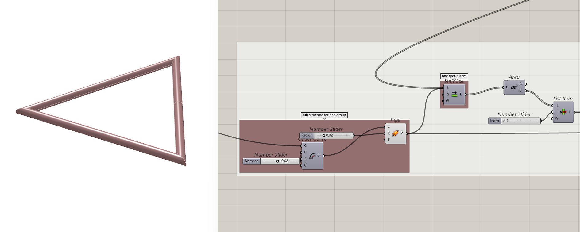
Step 2.6: The last step is to create the substructure on which the rhombus is fastened. A pipe is created along the rectangular polyline we created in step 2.2. This pipe is now distributed the same way as the facade elements in Step 2.5.
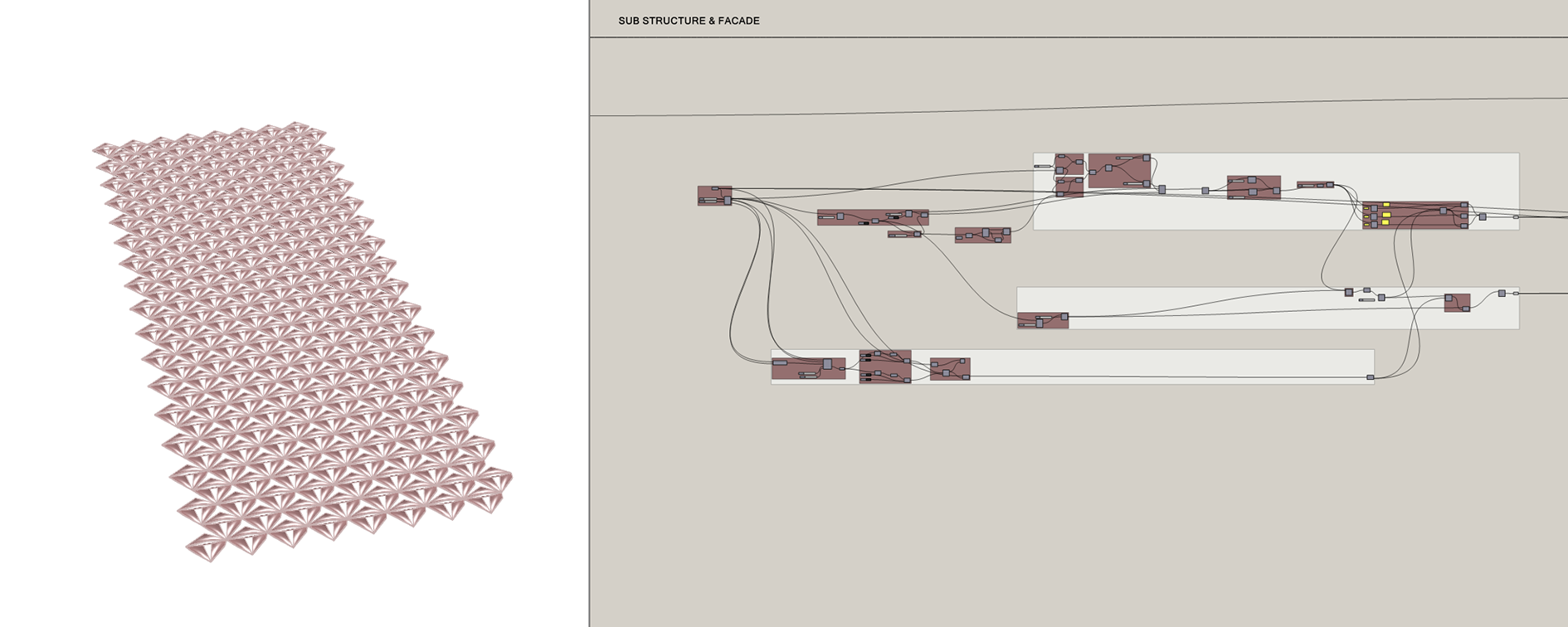
Full script of the sub structure and the facade:
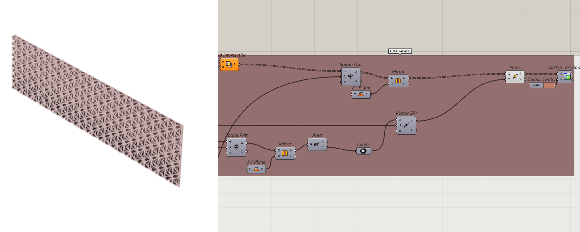
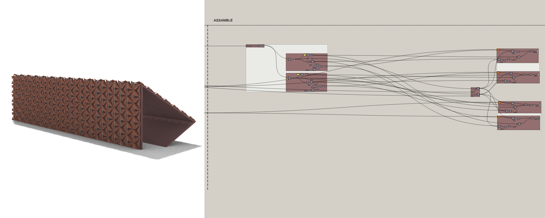
3. ASSAMBLE:
Step 3.1: After creating the different elements of our structures, they need to be assembled.
Step 3.2: First create a planar surface of the supporting structure.
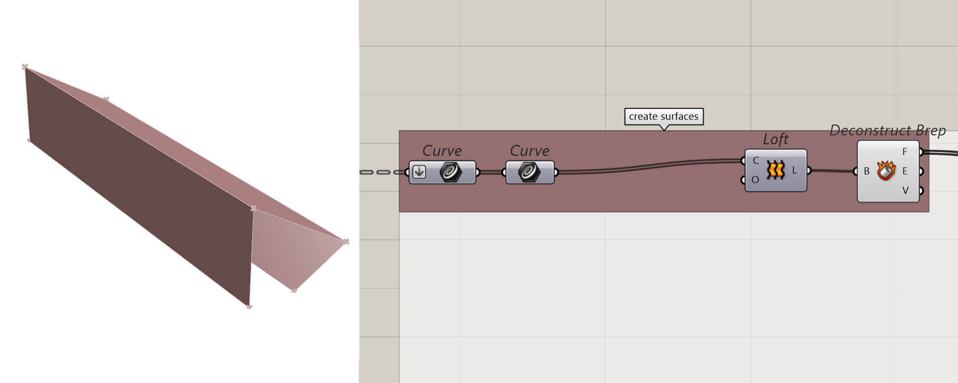
Step 3.3: Offset the surface so the substructure will be on the supporting structure and not intersecting with it.
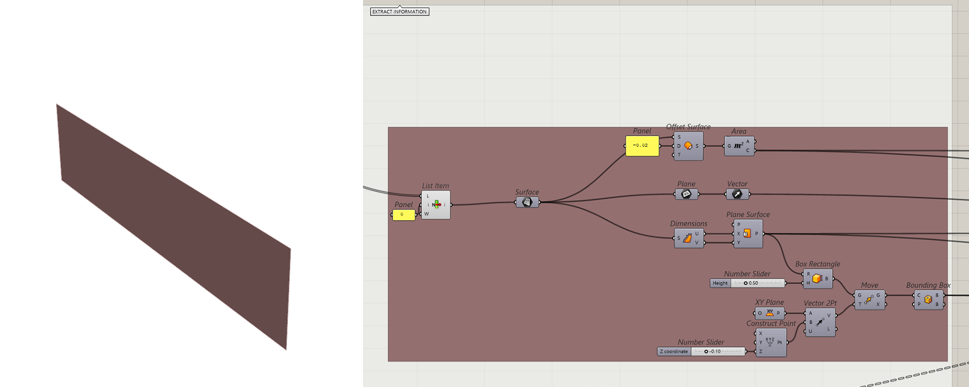
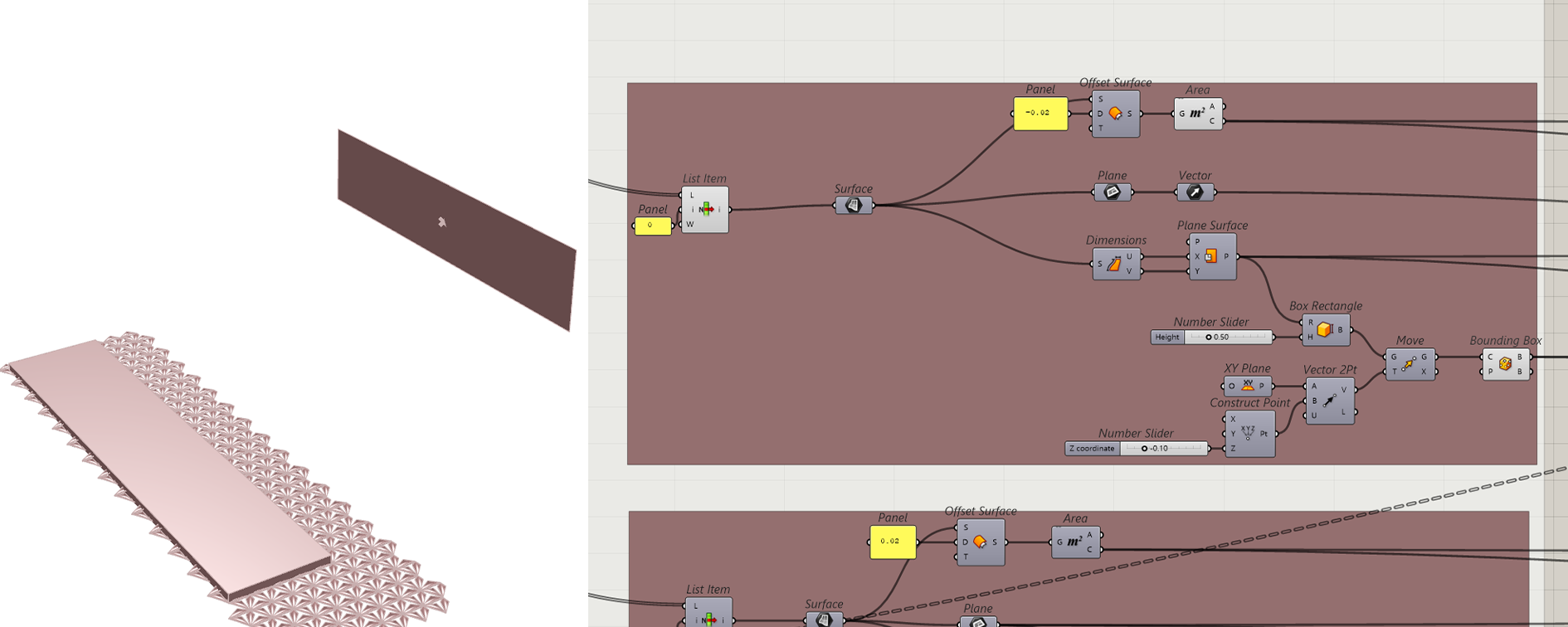
Get the center of the surface, as the aim point. Get the vector of the surface to create the right angle to rotate the facade. Get the dimensions of the surface to create a bounding box with the same dimensions as the surface.
Step 3.4: Create a solid Intersection between the bounding box and the facade geometry.
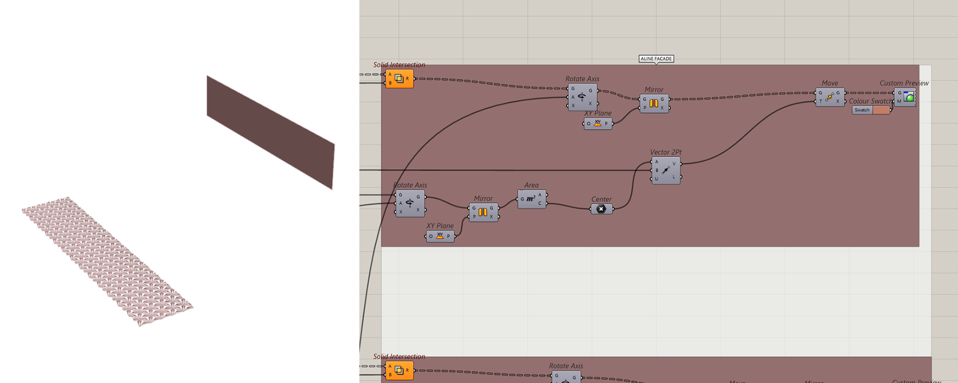
Step 3.4: Rotate and align the facade.
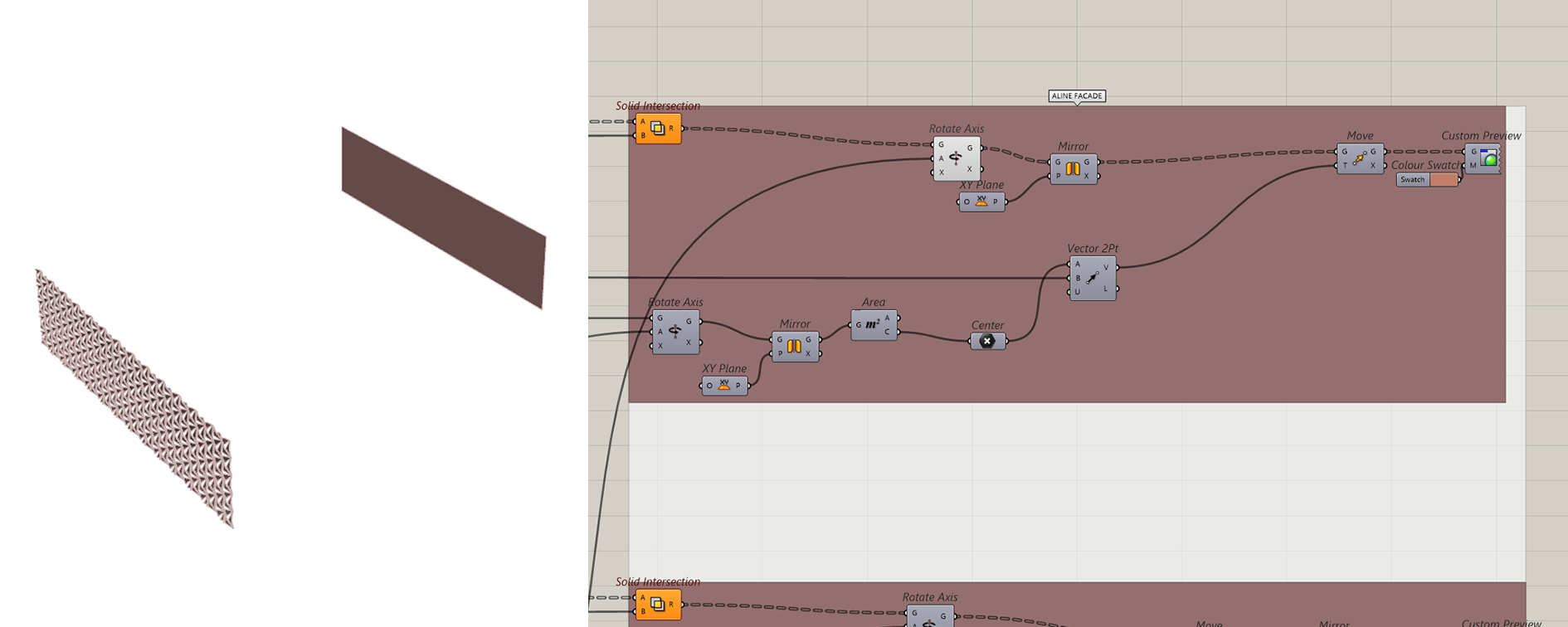
Step 3.5: Move the facade to the plane
Step 3.6: Repeat the Steps 3.1 -3.5 for the sub structure and all surfaces that need a facade.
Full script of assemble:
POSIBILITIES I
The facade closes and opens depending on the weather and how it effects the wood.
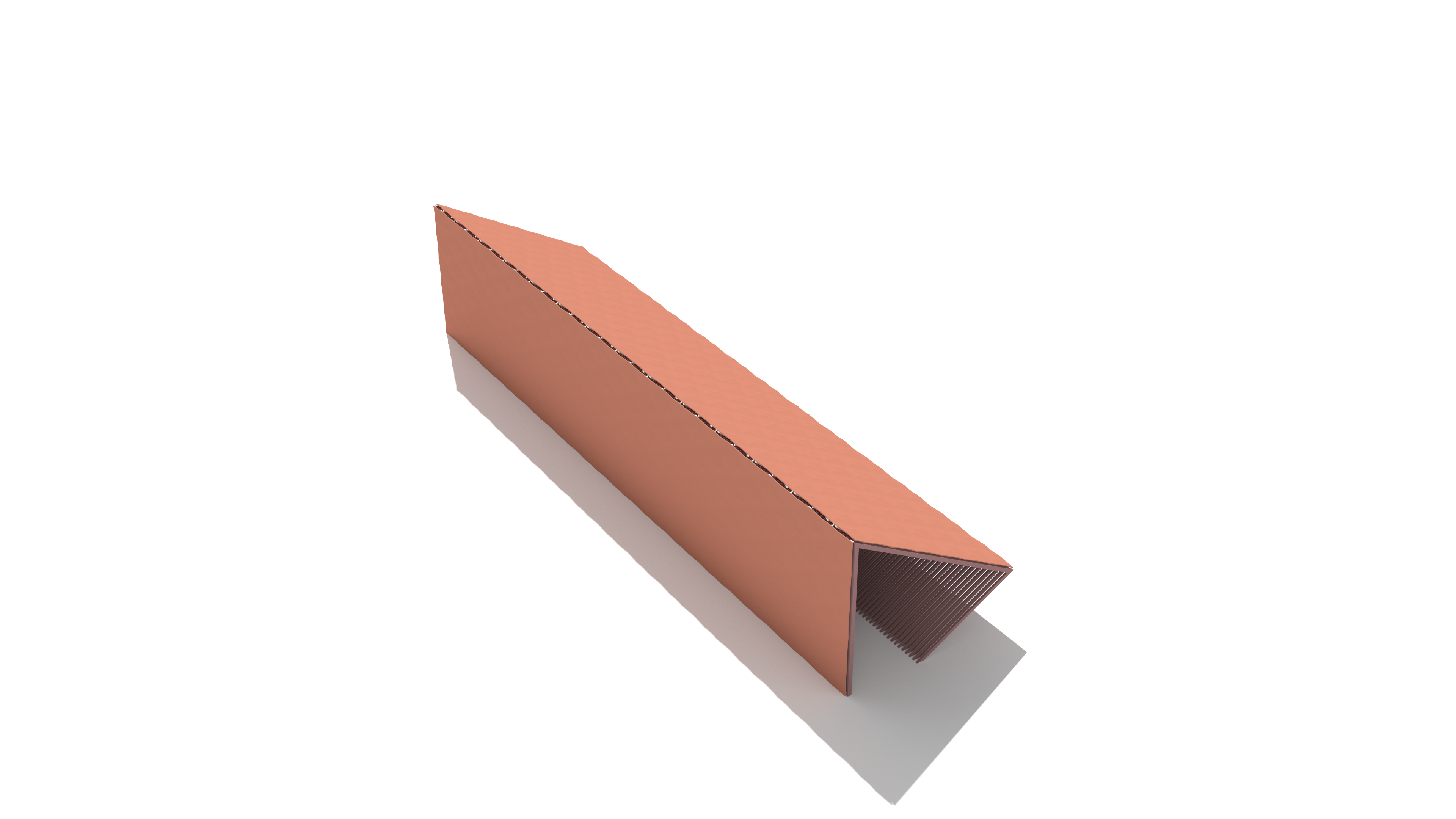

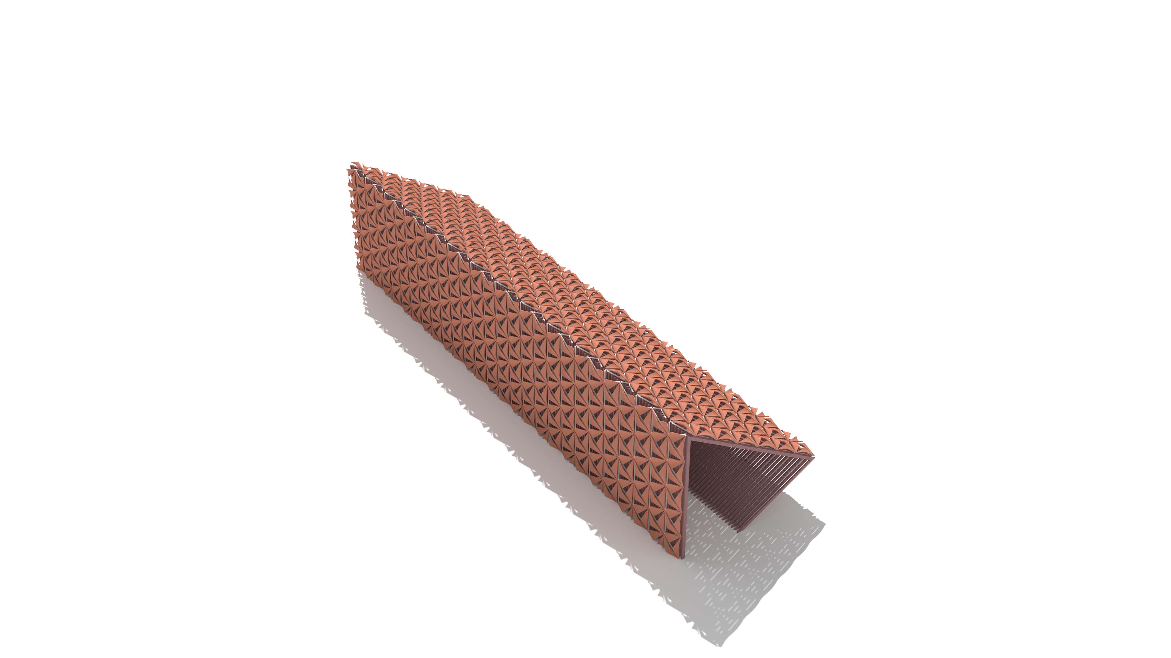
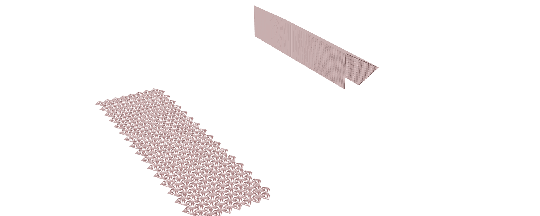
RESULT I
GRASSHOPPER FILE I