Concept and references
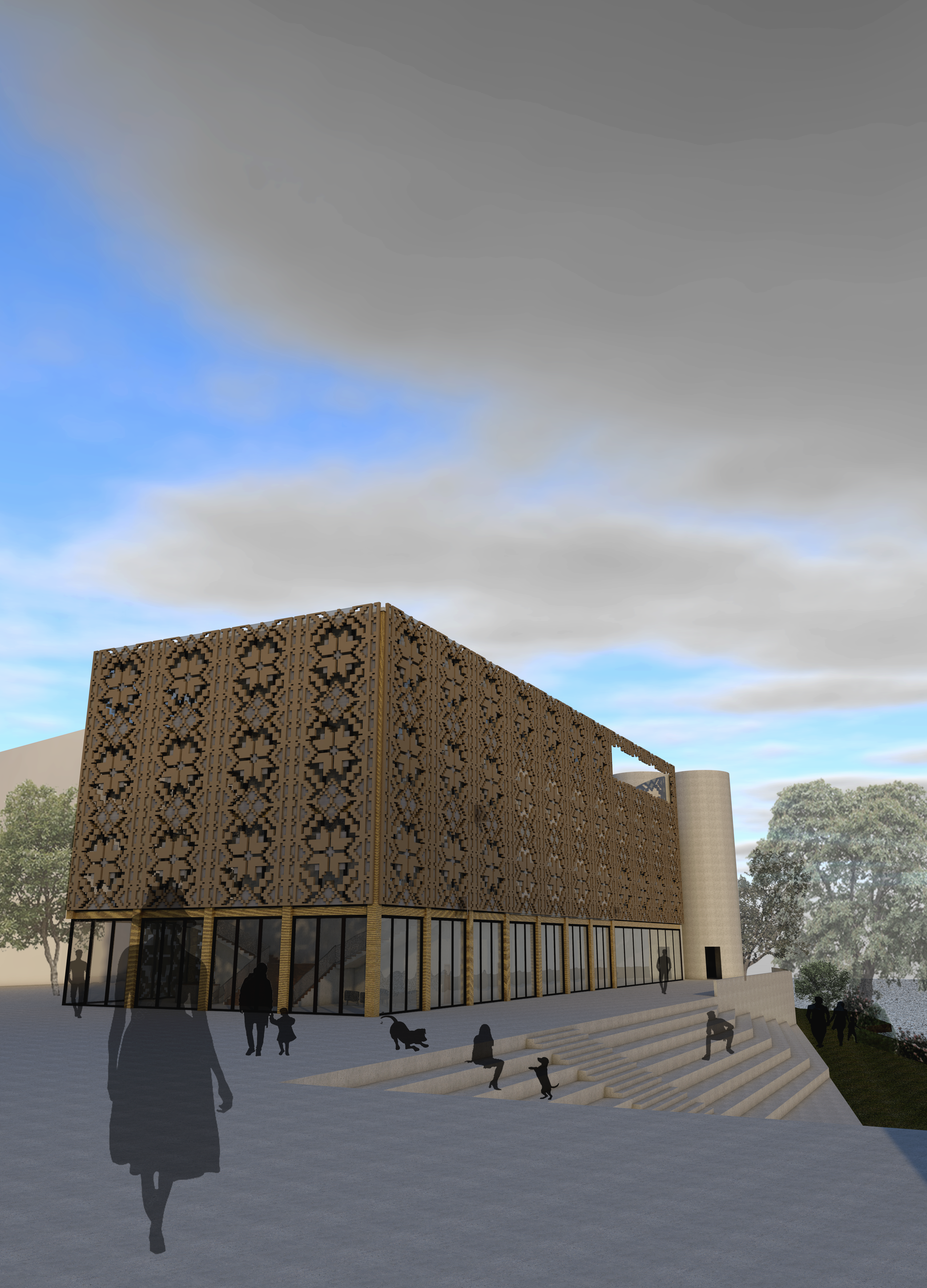
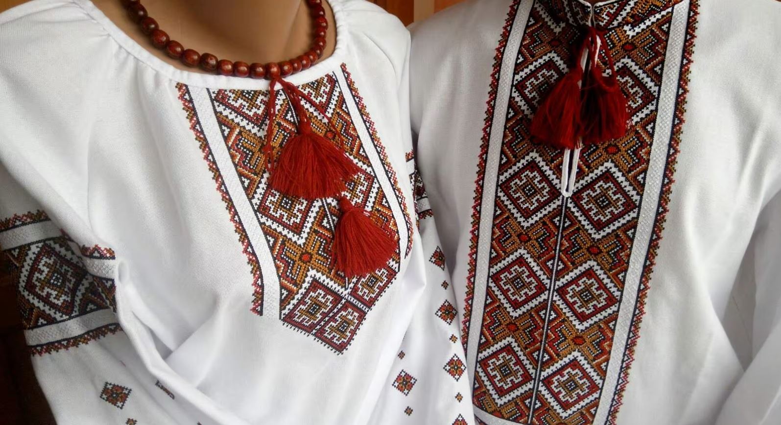
My project for the design studio was a Performing Arts Center focused on Ukrainian arts and culture (“House of Ukrainian performing arts”) so I wanted to include elements of Ukrainian culture in the architecture of the building. I then came up with idea of creating a double skin inspired by the Vyshyvanka pattern to give the project a strong Ukrainian identity and to create an atmosphere inside, created by the shadows of the pattern on the facade panels.
The Vyshyvanka is a typical embroidered shirt pattern that is often seen as a symbol of Ukrainian culture.
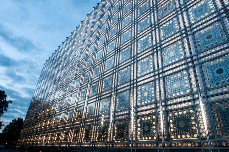
The concept is similar to the facade of Jean Nouvel’s Institut du Monde Arabe in Paris the reinvent the traditional Moucharabieh, with a distinct pattern that is often present in the architecture of Arab countries. This is somehow an architectural reinterpretation of cultural elements of a culture this programs aims to pay tribute to, which is similar to my goals by designing a House of Ukrainian performing arts.
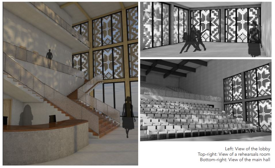
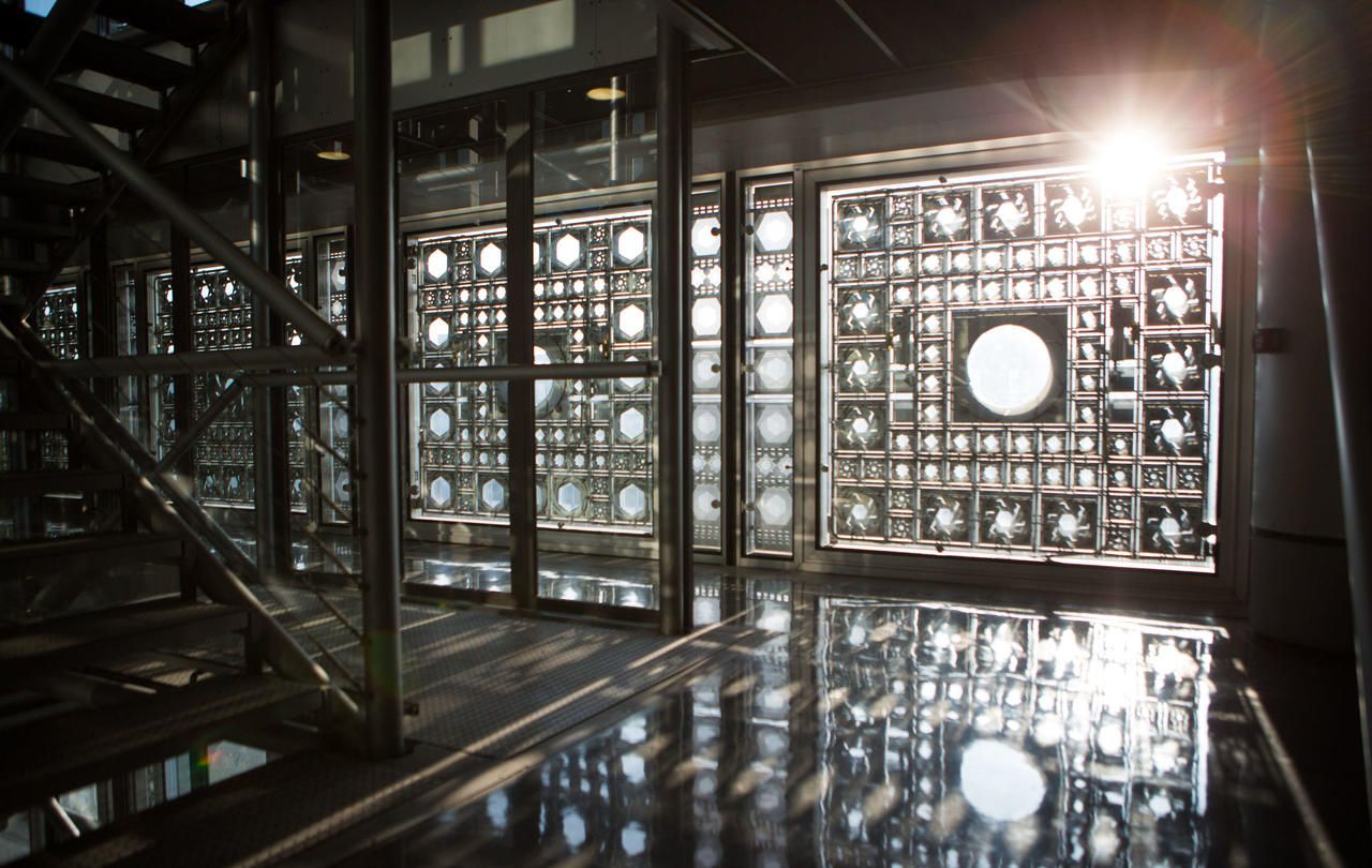
These panels also create an atmosphere inside, playing with lights and shadows, which is also something I wanted in my project
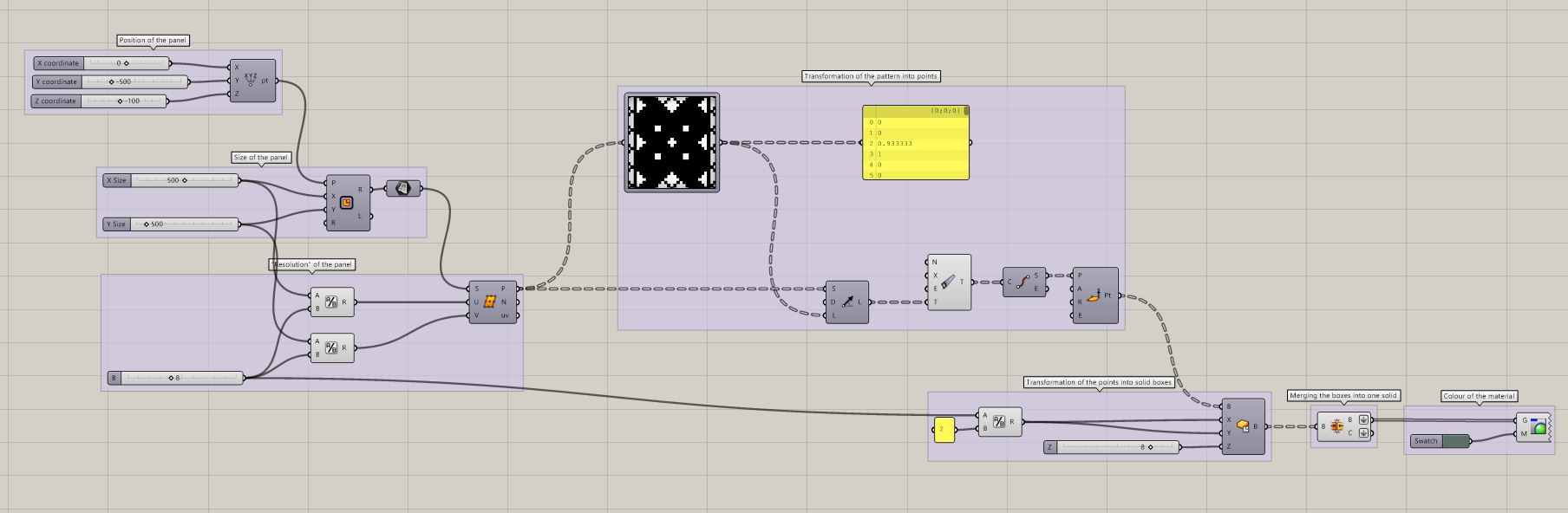
Overview of the file
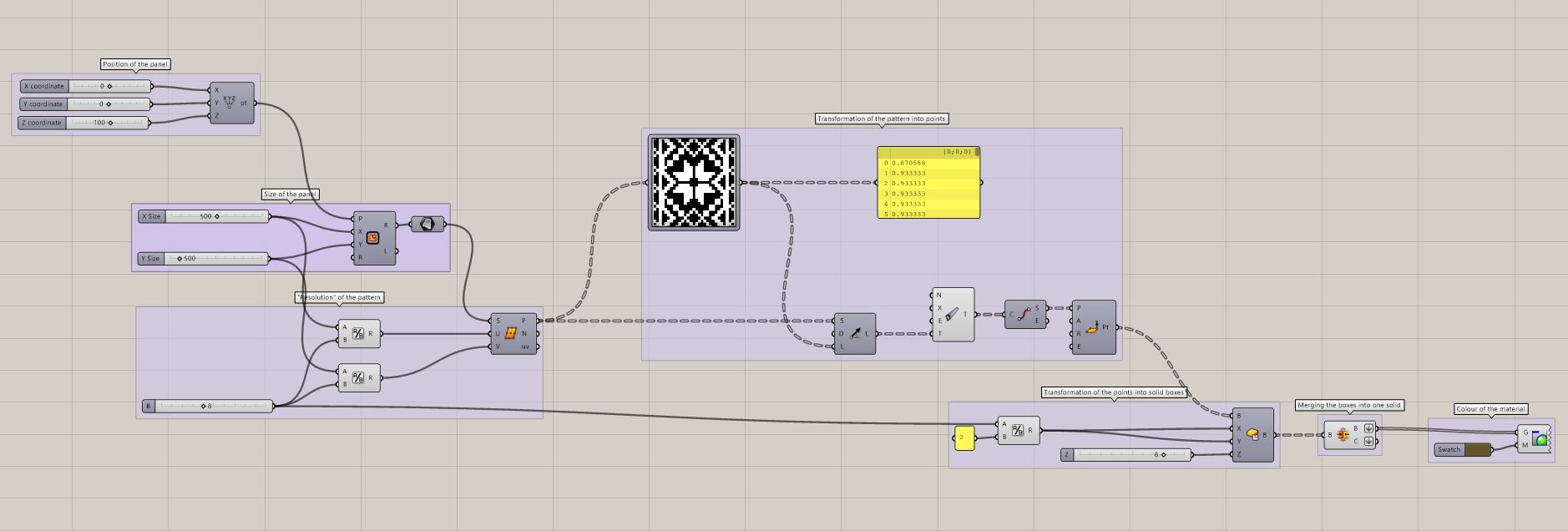
Step-by-step tutorial
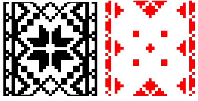
Step 1 // Creating a pattern
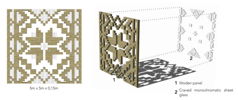
Using PhotoShop, you have to draw the patterns (with transparent background) you want to use and recreate with Grasshopper. In my project, I wanted my panels to have two layers of pattern with different materials so I had to create two patterns that I would use in different scripts.
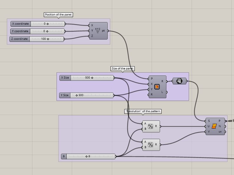
Step 2 // Defining the size and “resolution” of the panels
On Grasshopper, you first need to set the panels used for the facade. In my case the panels were squares with sides of 5 metes (500 cm). So you have to set a rectangle with 500 as a value in the X and Y parameters and turn it into a surface.
You also have to set what I would call a “resolution” for your panels (how many points your surface will include) which you define by the complexity of the pattern (also by how much you’re computer can bare). For this, you can use “Divide Surface”, you divide the X size and Y size values by how close you want your points to be (here I went for a point every 8cm in both X and Y direction) and put those values in the U and V parameters. This will create a list of points within the frame of the panel, spaced according to the chosen value.
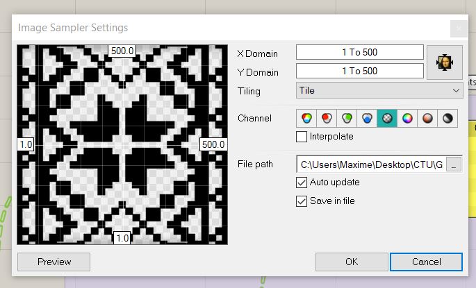
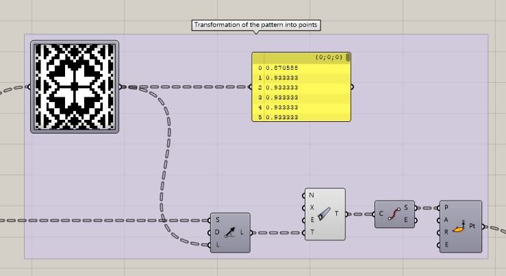
Step 3 // Sampling the patterns
Use the component “Image Sampler” and upload the image file of your pattern (one colours on transparent background). In the X Domain and Y Domain parameter, put 1 To xx (xx being the size of your panels, here: 500 cm)
Step 4 // Turning the patterns into points
Link your divided surface (cf. step 2) to the image sampler and to the “Start” input of a SDL Line component, link the image sampler to the “Length” input. This will draw lines from each point of the divided surface that is part of the pattern.
This created invalid values (Lines with a length of 0 where the pattern is transparent). You have to use “Clean Tree” and “End Points” components to get rid of those invalid values. You will then have a list of points that correspond to the pattern you put in the image sampler.
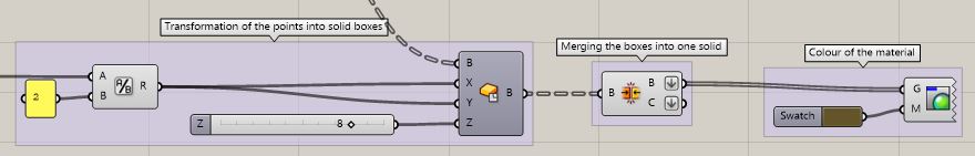
Step 5 // Creating a solid of the pattern
Create boxes out of the list of points gotten from step 4 using “Center Box”. These point will be base point of each box. This will create as many boxes as there are points from step 4. You can merge them all in one solid using “Brep Join”. Flatten the B and C output to be able to bake them into Rhino and modivy them.
If you want the boxes to touch each other to create one single continuous solid and because these are center boxes, the X and Y values have to be equal half of the span between two points of the diveded surface from step 2 (Here 8cm / 2 = 4cm).
Step 6 // Exporting the shapes and using them in rendering and BIM 3D models
You can bake the boxes once they are merged into one single solid to use it on Rhino or export it to your favourite 3D modeling software (ArchiCAD, Sketchup, etc.) and include it in renders.