Why and what?
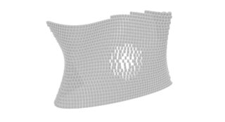
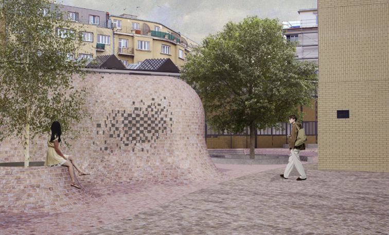
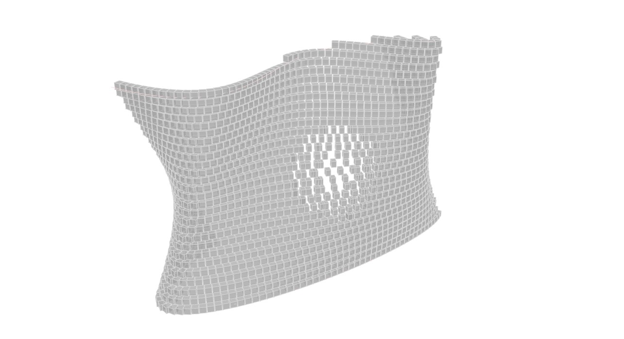
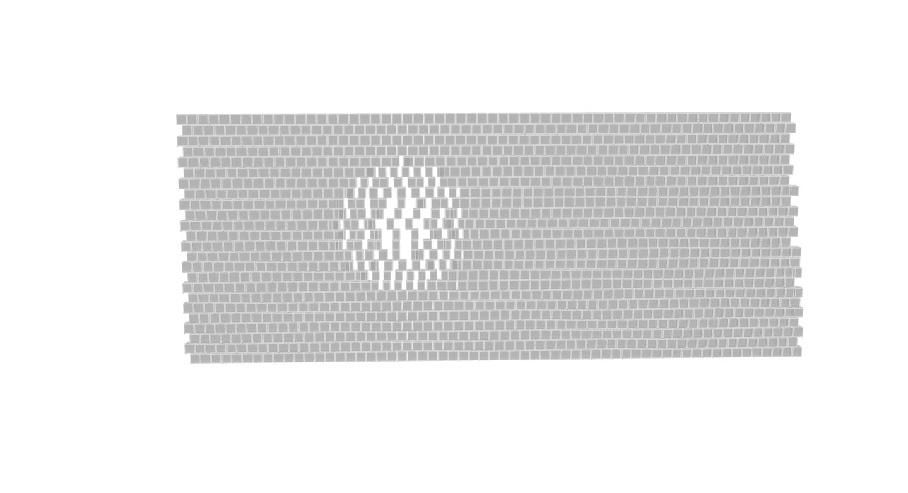
In this project, I focused on creating a perforated façade made of granite blocks on both flat and curved surfaces. The final effect is inspired by the idea of an unravelling sweater – a surface that gradually opens up and becomes more porous instead of remaining rigid and uniform.
Creating this kind of transition manually would be very difficult and time-consuming, especially in Photoshop or by placing each block one by one in a modelling program. This Grasshopper script makes the process much easier by generating the block pattern automatically and allowing me to control the perforation parametrically. With the help of attractor geometry, the bricks can gradually shift, open, and create larger gaps in selected areas, while still following either a straight or curved façade. This makes it possible to quickly test different design variations and create a façade that combines solidity with lightness, transparency, and a dynamic visual effect.
Original Photoshop picture
New geometry from Rhino and Grasshopper
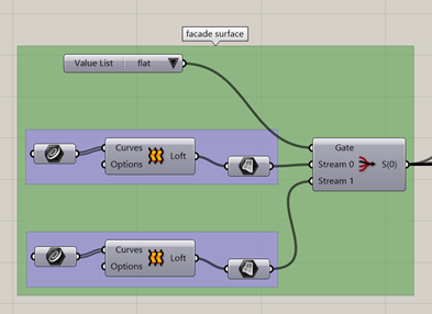
Step 1: Creating and selecting the façade surface
- Two input surfaces are created: a flat façade and a curved façade.
- The Value List and Stream Filter components are used to choose which surface will be developed.
- The selected surface becomes the base geometry for all later operations.
This makes the script flexible, because the same perforation system can be tested on different façade shapes.
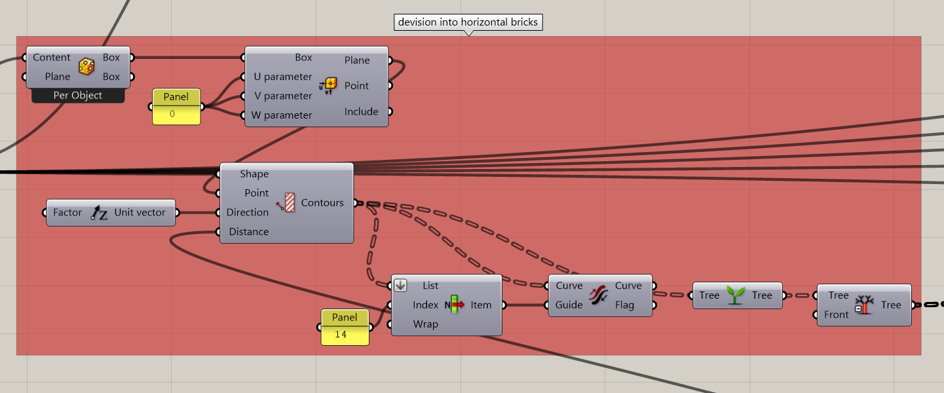
Step 2: Dividing the surface into horizontal brick rows
- The selected façade surface is divided using the Contour component.
- A vertical vector controls the direction of the contours, creating horizontal rows across the wall.
- The distance between the contours controls the vertical spacing between the rows.
- The curves are organised and flipped where necessary so that all rows follow a consistent direction.
These contour curves form the basic lines on which the granite blocks will later be placed.
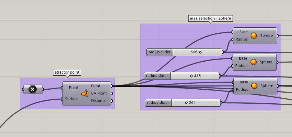
Step 3: Creating the attractor area
- An attractor point is placed on the selected façade surface.
- Three spheres are created from this point with different radii.
- The spheres define three levels of influence: inner, middle and outer.
The attractor area controls where the façade begins to open. The smallest sphere creates the strongest perforation, while the larger spheres create a gradual transition back to the normal wall.
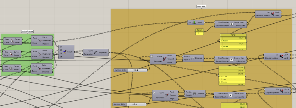
Step 4: Dividing the rows into perforation zones
- The contour curves are intersected with the three spheres using Brep | Curve.
- The intersection points are converted into curve parameters.
- These parameters are merged and used in Shatter to split each row into separate segments.
- The segments are sorted into different zones using Evaluate Curve, Distance, Smaller Than and Dispatch.
This divides the wall into four spacing areas:
- normal façade area,
- outer transition area,
- middle transition area,
- inner opening area
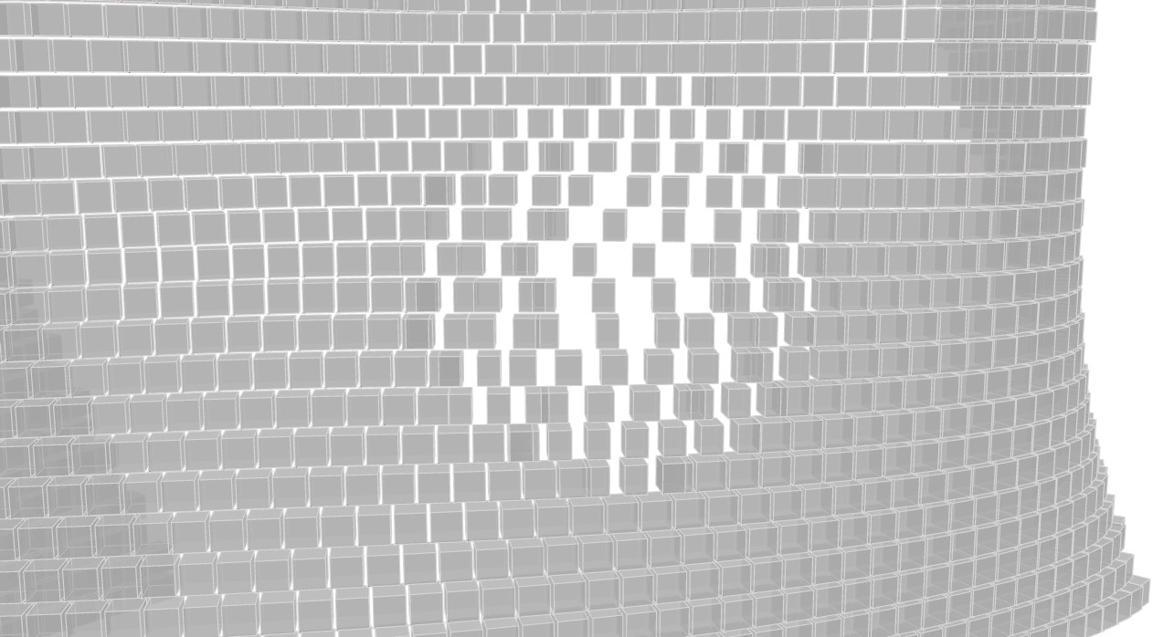
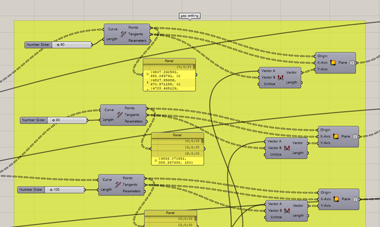
Step 5: Controlling the gaps between the blocks
- Each perforation zone is divided separately using Divide Length.
- The normal façade uses the smallest spacing between blocks.
- The spacing becomes progressively larger towards the attractor point.
- This produces a smooth opening effect instead of a sudden hole in the wall.
The spacing follows this principle:
normal spacing → small opening → medium opening → largest opening This gradual change creates the visual effect of the façade slowly coming apart, similar to threads loosening in an unraveling sweater.
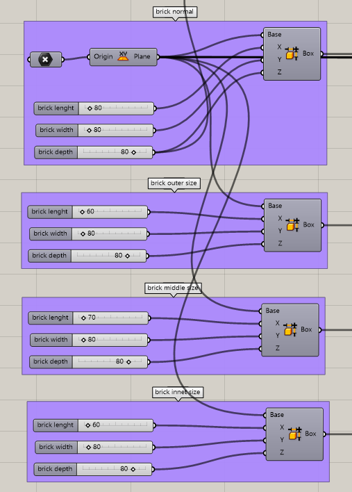
Step 6: Creating different granite block sizes
- A basic block is created using the Box component.
- Separate block sizes are created for the normal, outer, middle and inner zones.
- The blocks inside the perforated area can be made smaller where necessary to avoid overlap.
- The normal part of the façade keeps the original block size.
This adjustment makes the perforation readable and prevents the shifted blocks from colliding with one another.
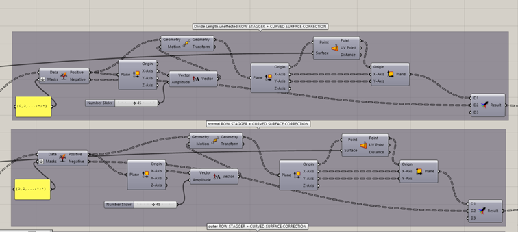
Step 7: Creating the staggered masonry pattern
- For each zone, the placement planes are separated into alternating rows using Split Tree.
- Every second row is shifted horizontally by half of the normal brick module.
- This creates the typical staggered arrangement of masonry instead of placing all blocks directly above each other.
The shifted rows make the façade pattern appear more natural and strengthen the textile-like character of the design.
Step 8: Correcting the blocks on the curved surface
- On a curved wall, shifting the blocks in a straight direction can move them away from the façade surface.
- The shifted placement planes are therefore analysed using Deconstruct Plane.
- Their origins are projected back onto the façade with Surface Closest Point.
- New corrected planes are reconstructed directly on the curved wall.
This allows the staggered brick pattern to follow the curved façade accurately instead of floating outside the surface.
Step 9: Generating the final façade geometry
- The corrected placement planes from each zone are connected to separate Orient components.
- Each zone receives its corresponding granite block size.
- The normal, outer, middle and inner block groups together form the final façade.
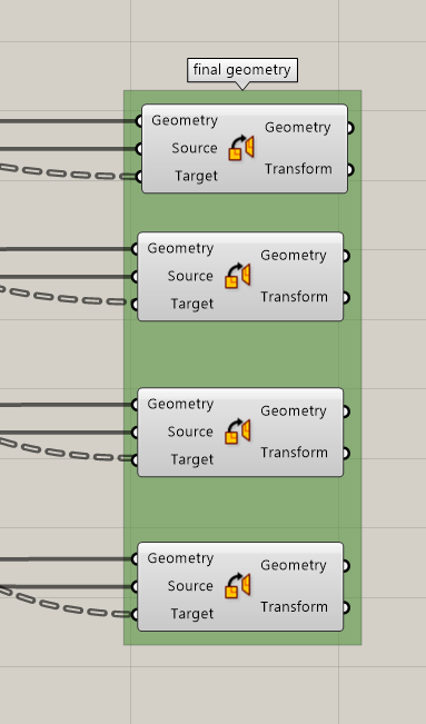
The final result is a parametrically controlled granite façade that gradually perforates around an attractor point. The wall transforms from a solid masonry surface into a lighter and more open structure, expressing the concept of an unraveling sweater through architectural geometry.