Aim
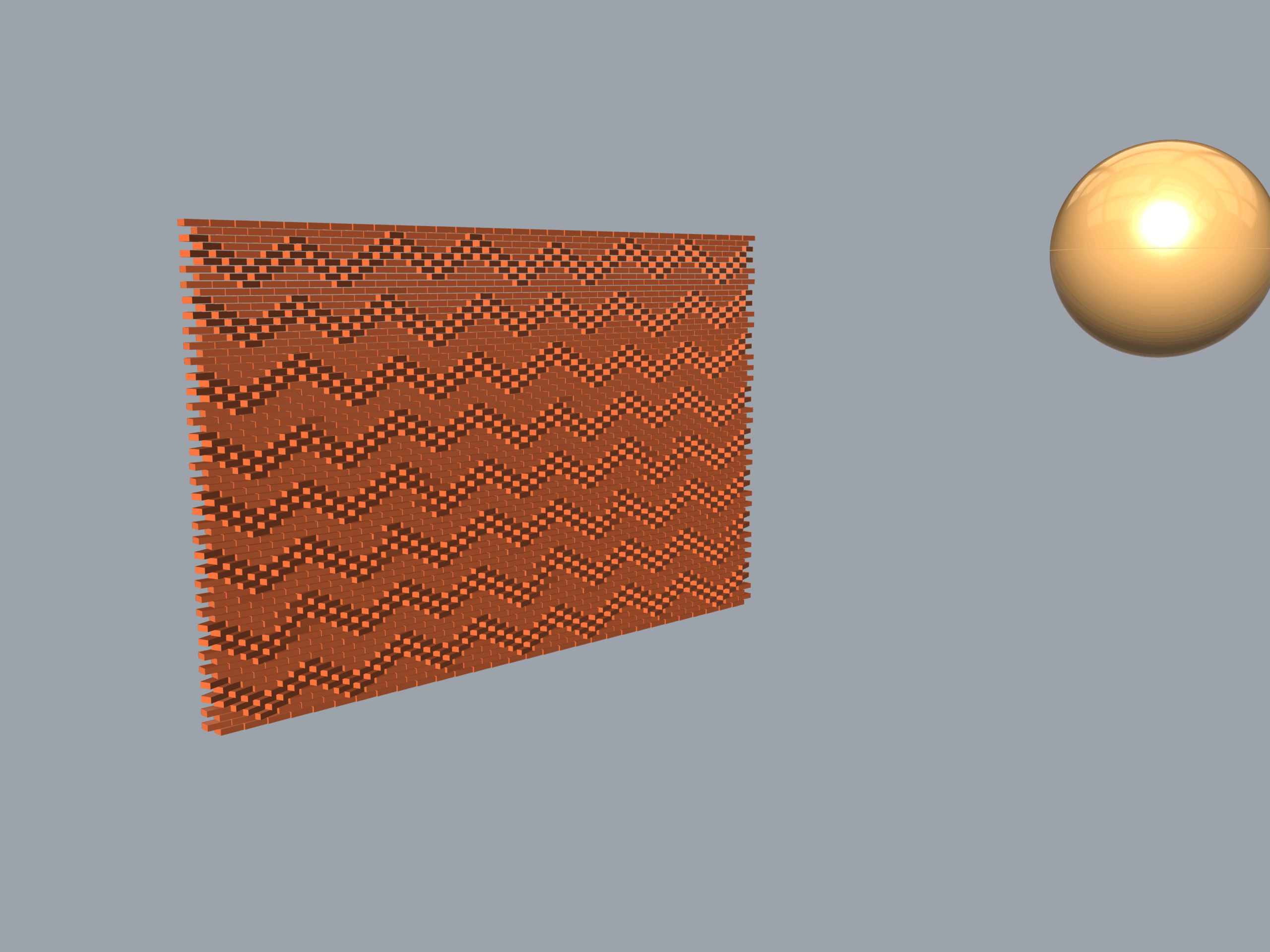
This project explores the digital fabrication logic and environmental performance of an adaptive brick masonry system. The algorithm generates a parametric wall with responsive rotation patterns controlled by (1) a Point Attractor or (2) an Image Sampler. Additionally, it integrates a custom vector-collision engine to analyze solar permeability and daylight performance through the façade in real-time.
Use examples
Script
- Creation of Parametric Brick Wall.
- Bricks rotation:
- a. Based on point attractor.
- b. Based on image.
- Vector Collisioning.
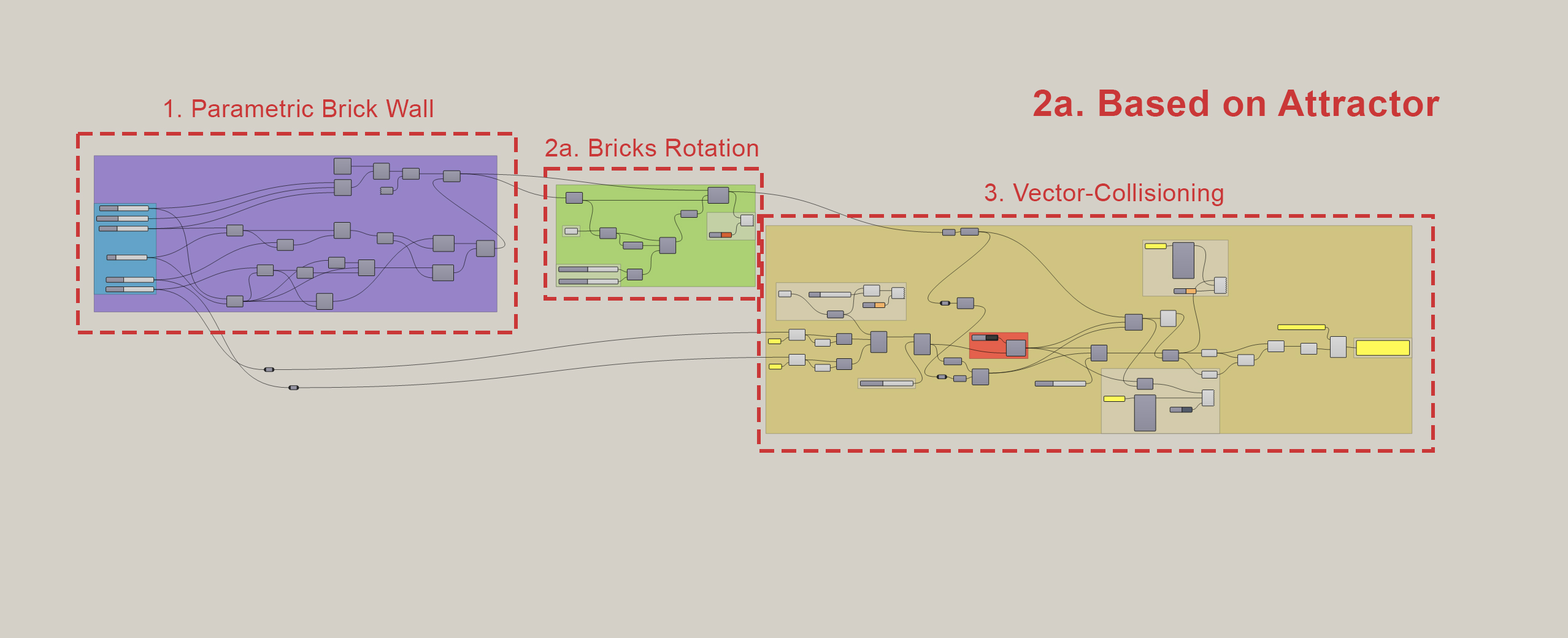
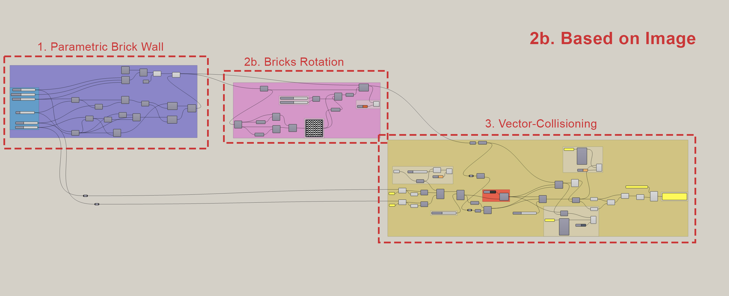
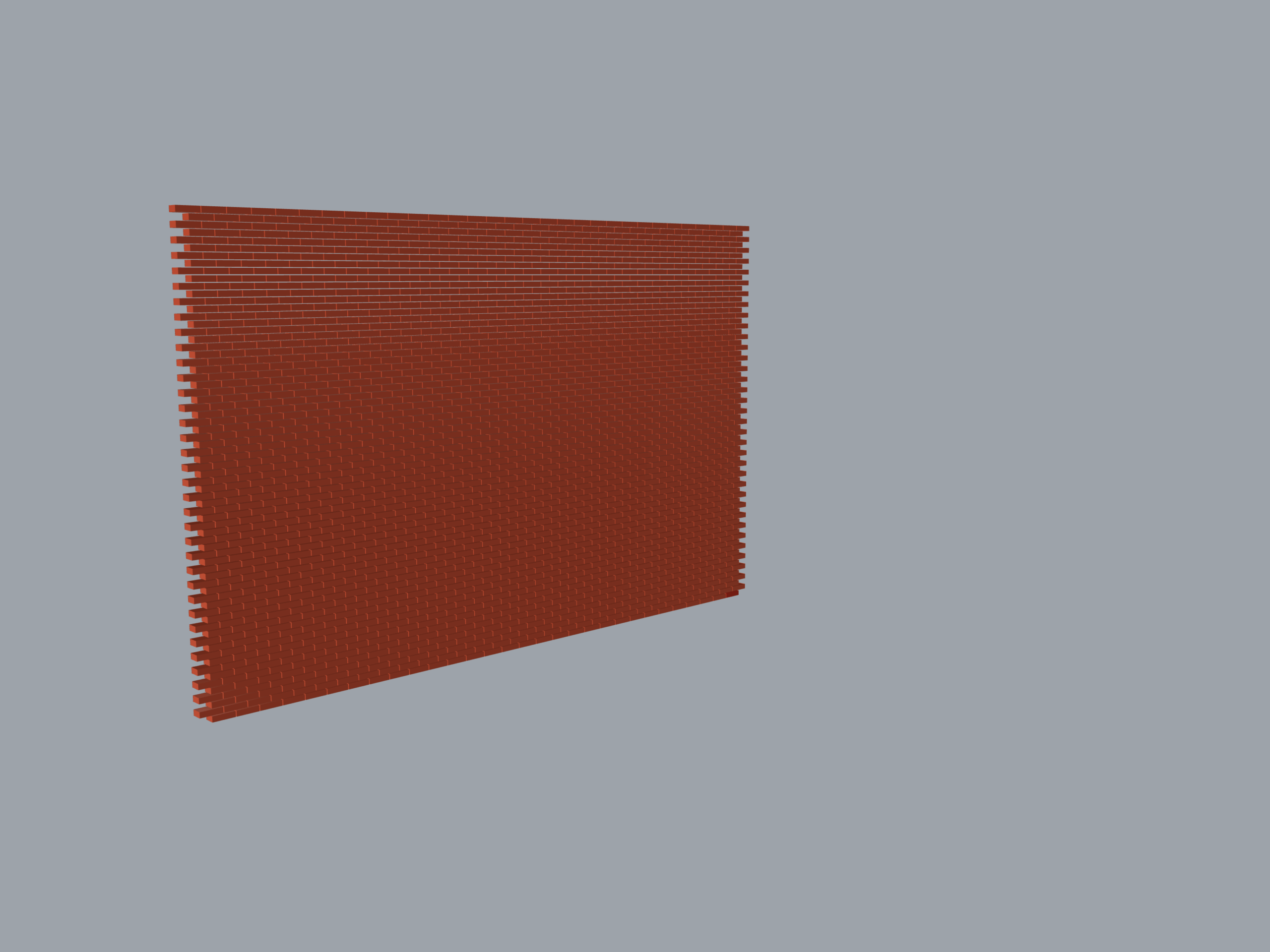
1. Creation of Parametric Brick Wall
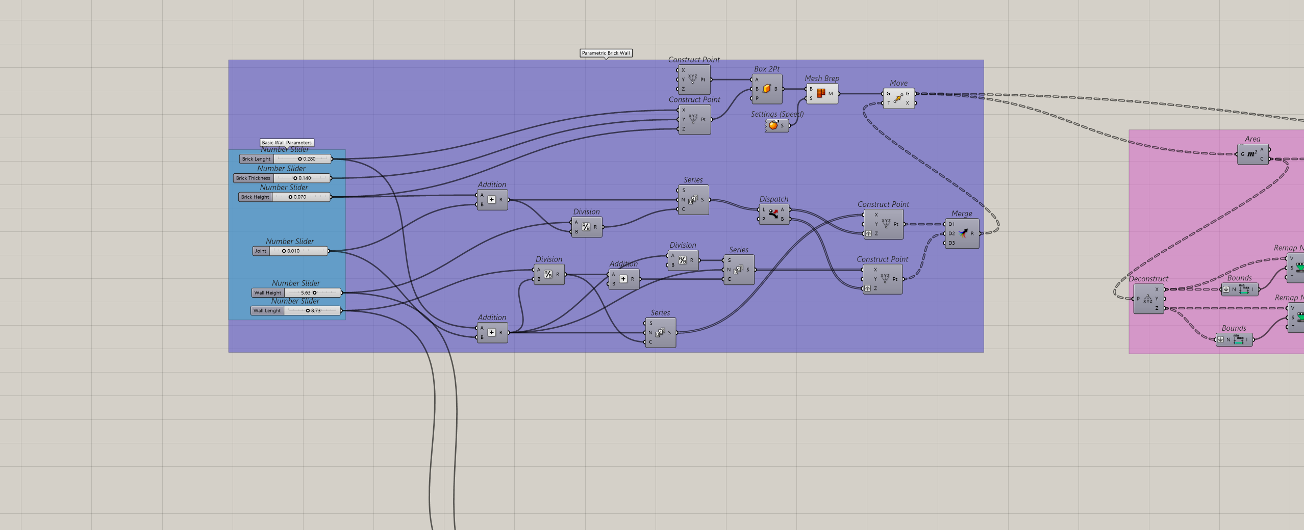
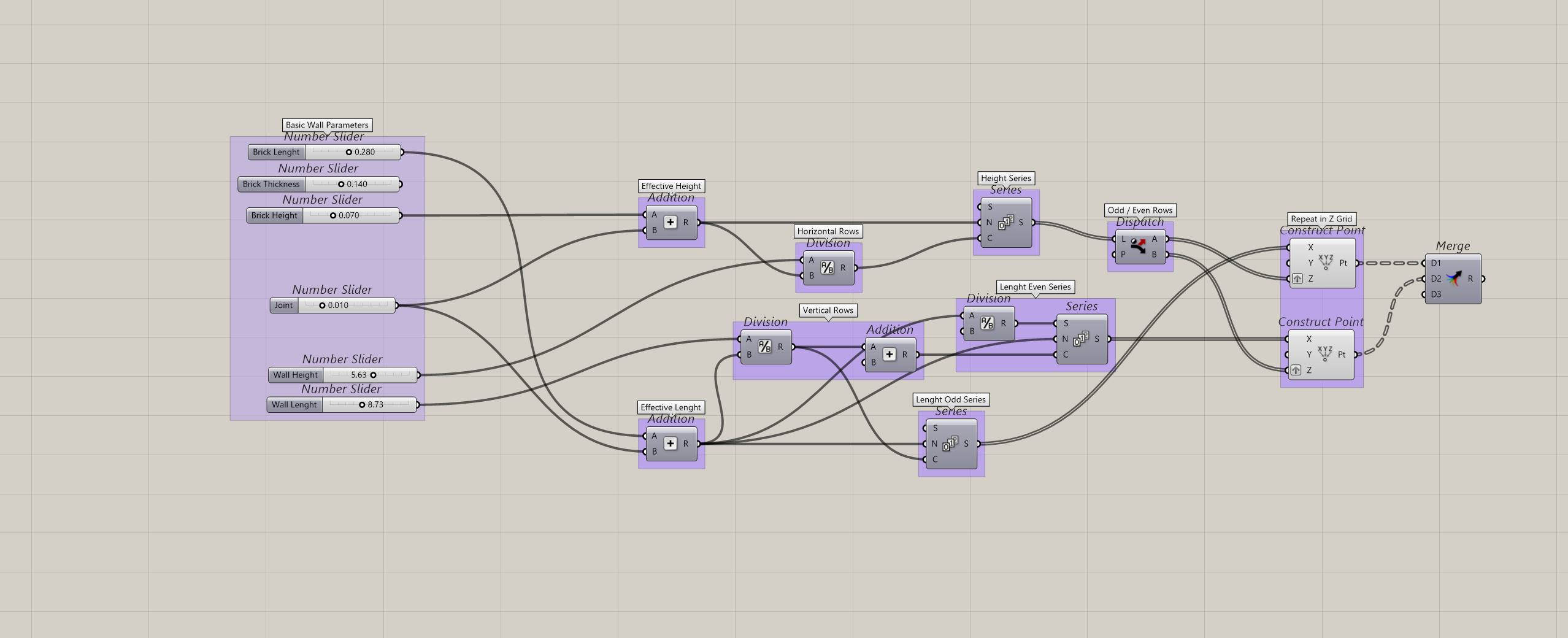
1.1 Parametric brick grid
Effective Dimensions: Adds Brick Lengt, Height and thickness. Mortar Joint dimension to prevent any geometric overlapping.
Staggered Logic: Uses Series and Dispatch component to calculate rows, shifting every alternating row by half a brick length to generate the classic interlocking layout.
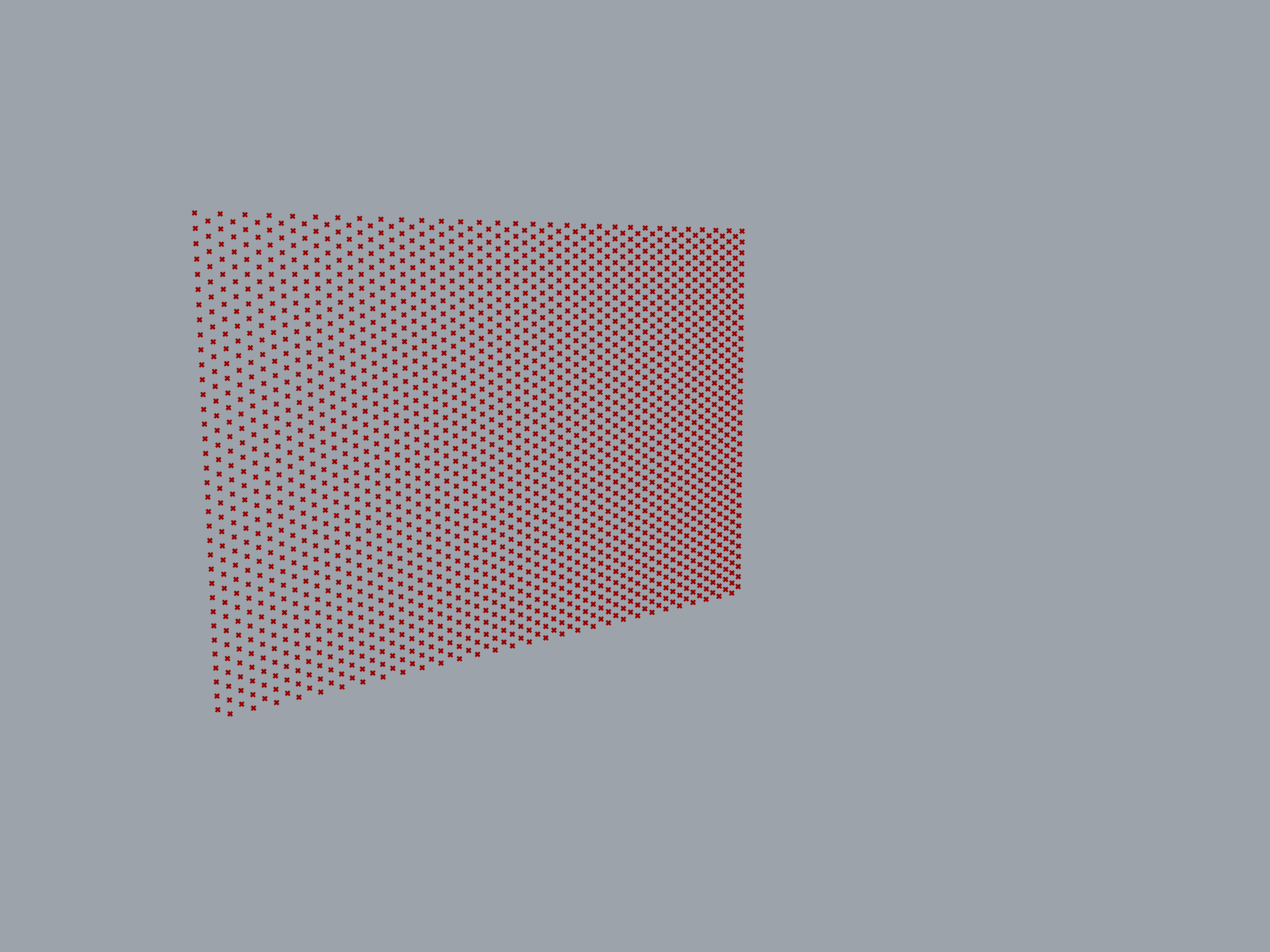
Grid Merge: Maps these coordinates into Construct Point (X, Y, Z). Then Merge organizes the points into a clean data tree, ready to anchor the 3D geometry.
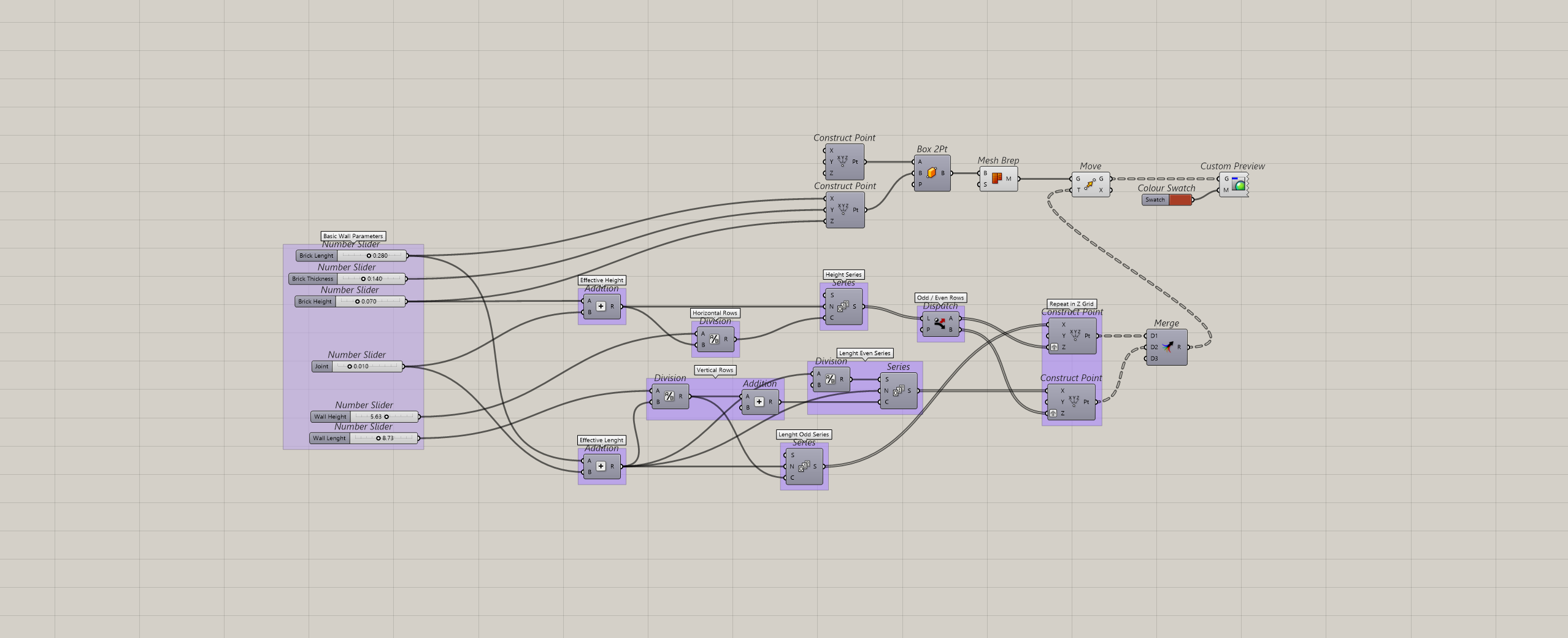
1.2 Bricks Generation
Box Creation: Box 2Pt generates a single, solid brick using coordinate bounds to match physical dimensions.
Mesh Conversion: Mesh Brep converts the solid box into a lightweight mesh to optimize processiong speed during updates.
Grid Population: Move duplicates and maps the optimized brick geometry onto every point of the staggered grid.
Color Preview: Custom Preview shakes on a custom material color display.
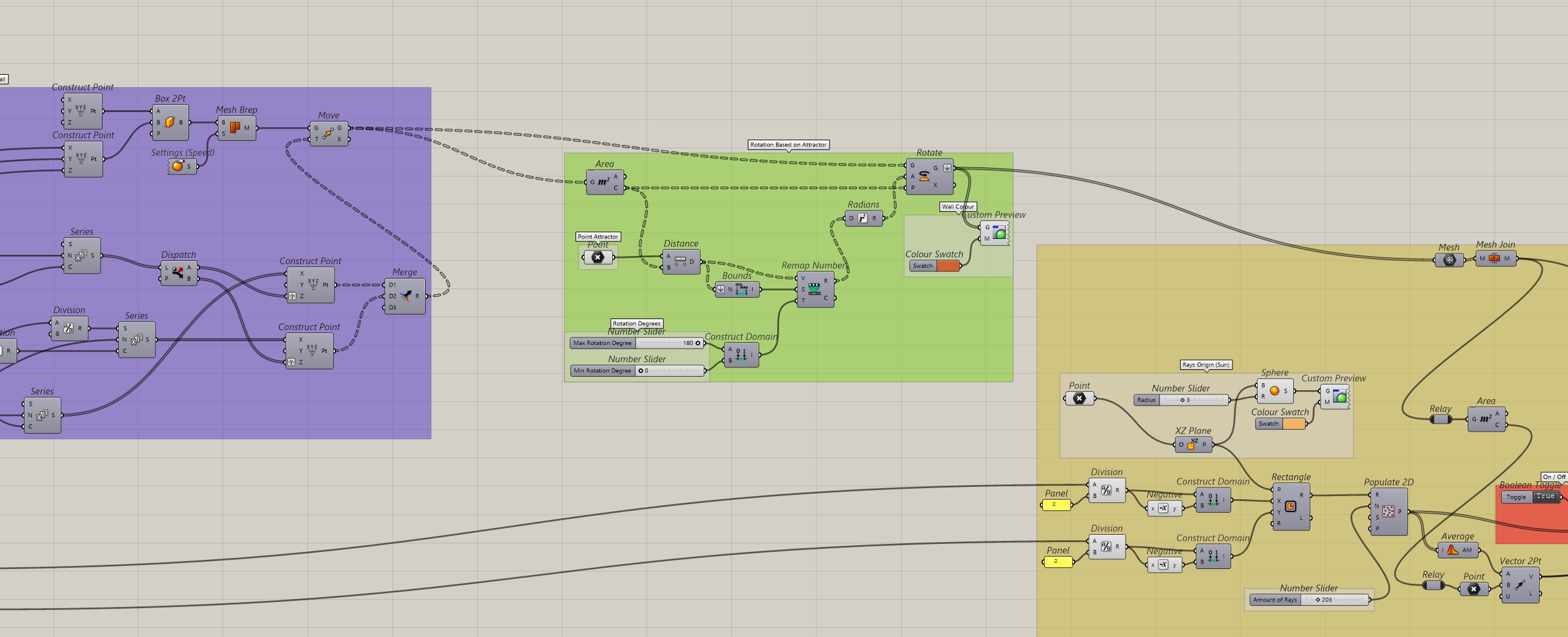
2. Bricks Rotation
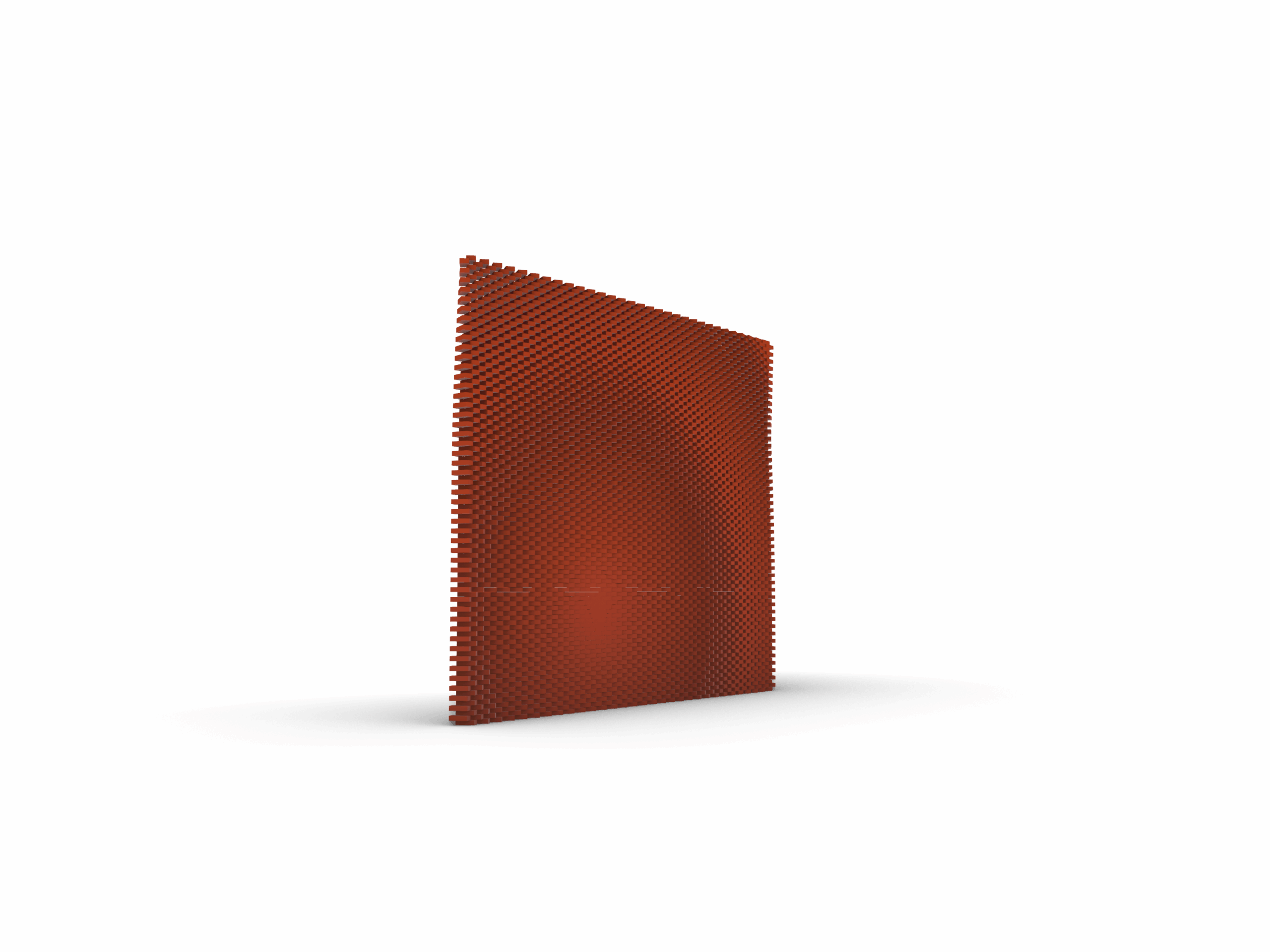
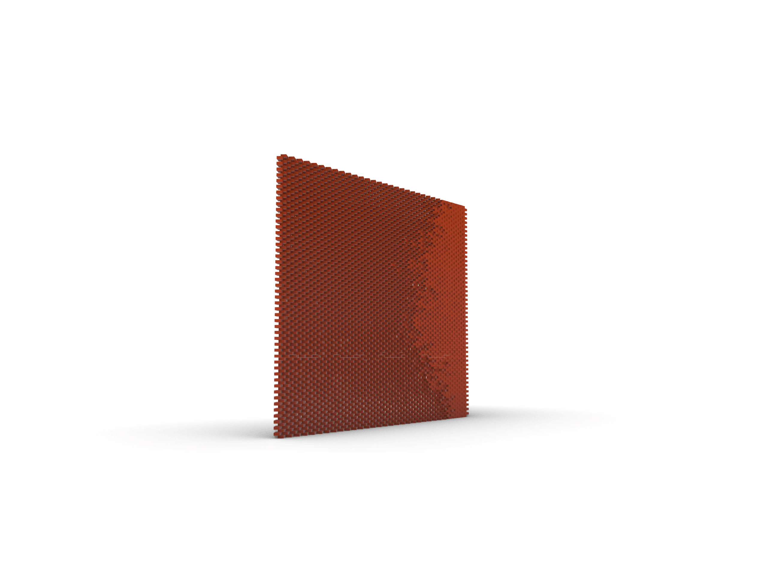
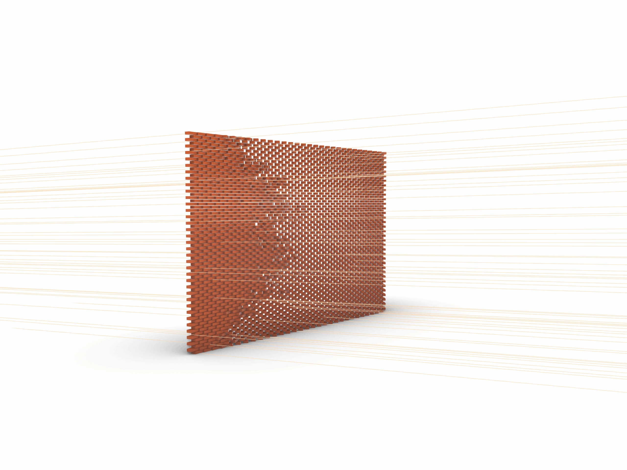
2a. Based on Attractor
This block drives the dynamic rotation of each brick relative to its proximity to a specific control point attractor.
Center Identification: Area calculates the exact centroid of every single brick to establish individual local rotation axes.
Proximity Mapping: Distance and Bounds mesaure the geometric distance bbetween each brick’s center an the interactive attractor point.
Domain Re-Mapping: Remap Numbers translates those raw distance values into a controlled angle range that can be adjustable, e.g. 0° to 180°, capturing the minimum and maximum extremes.
Angular Execution: Radians and Rotate convert the re-mapped degree values into radians, feeding them into the vector rotation component to dynamically twist the wall geometry aroun each local centroid.
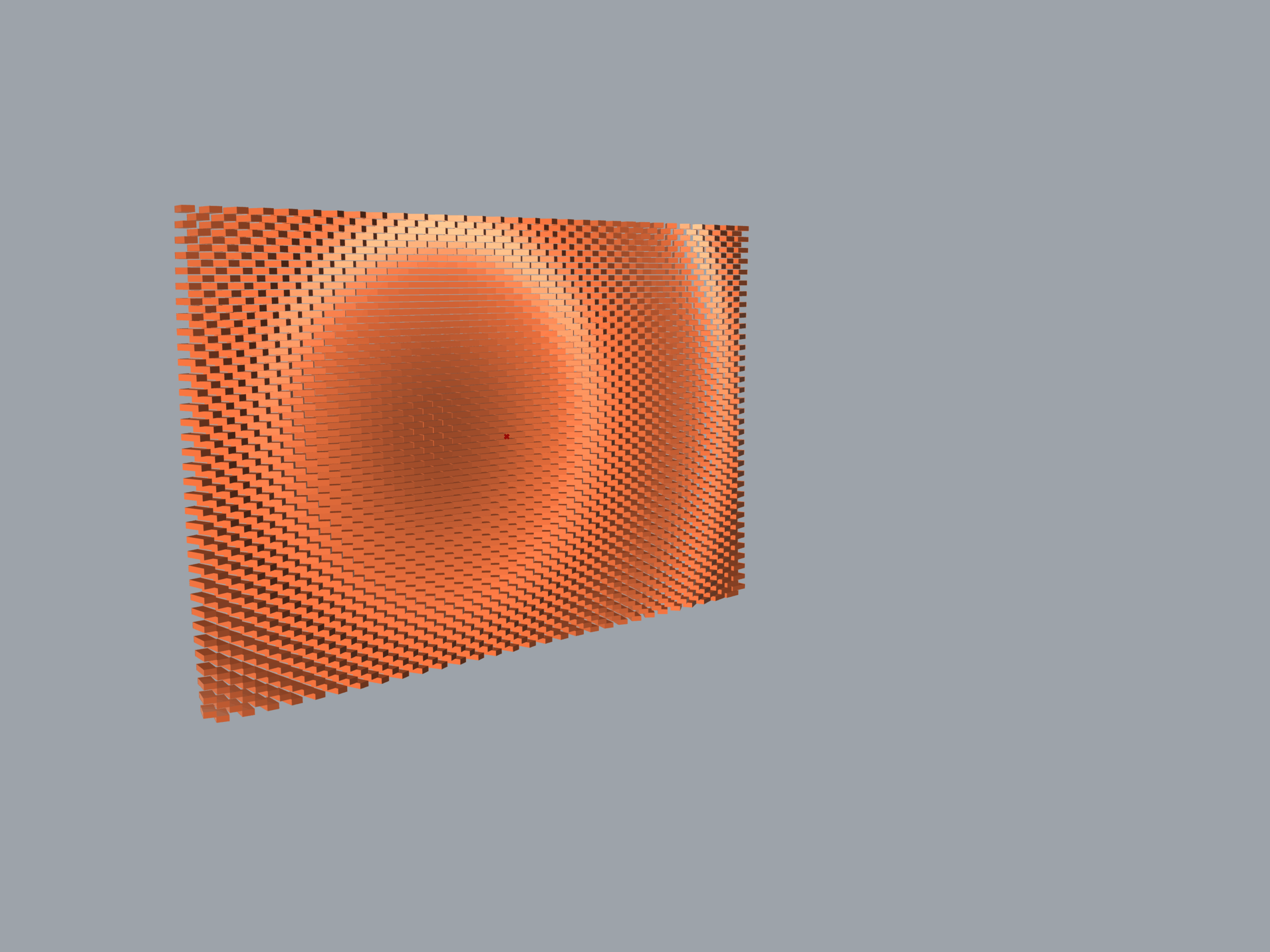
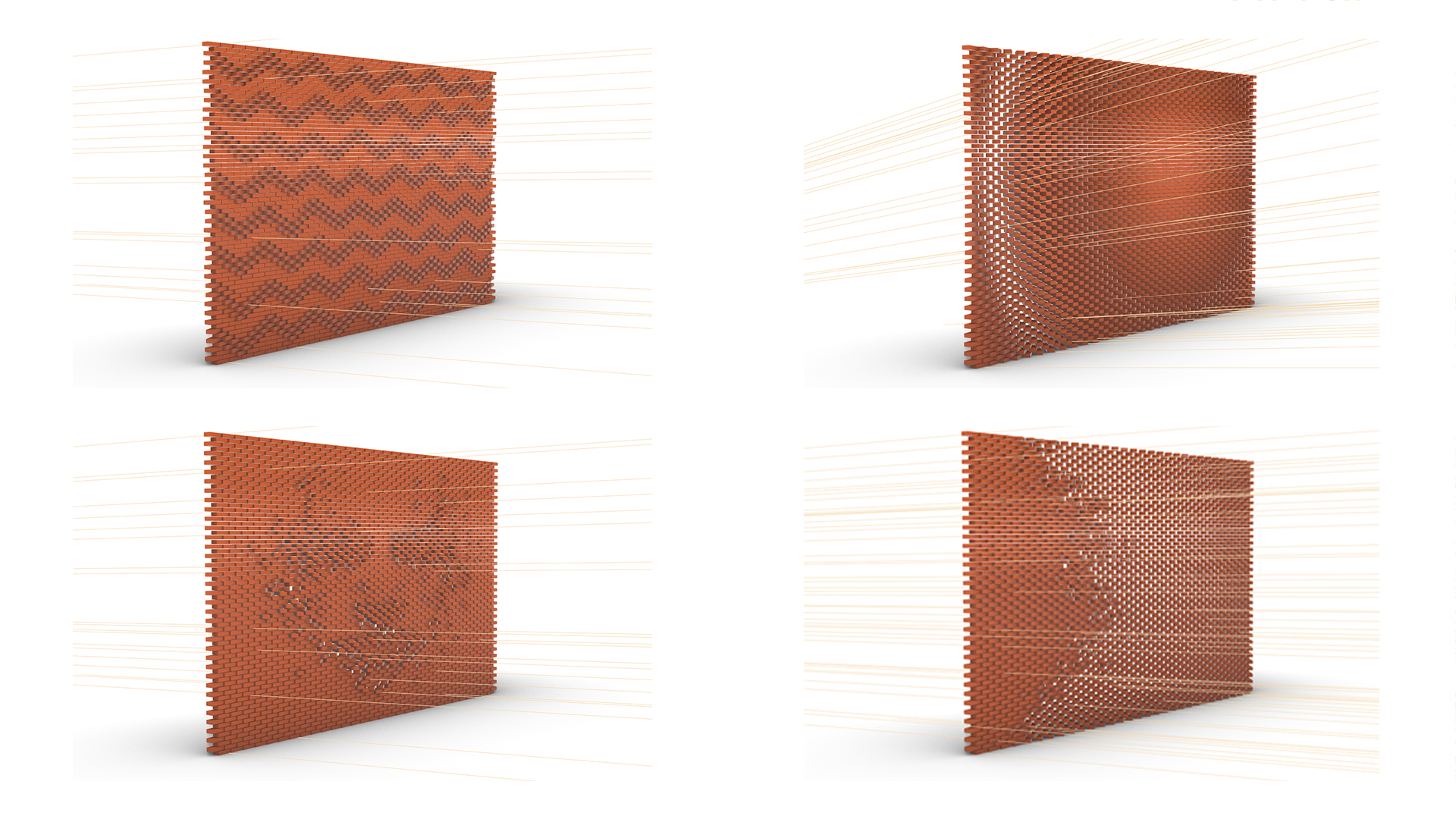
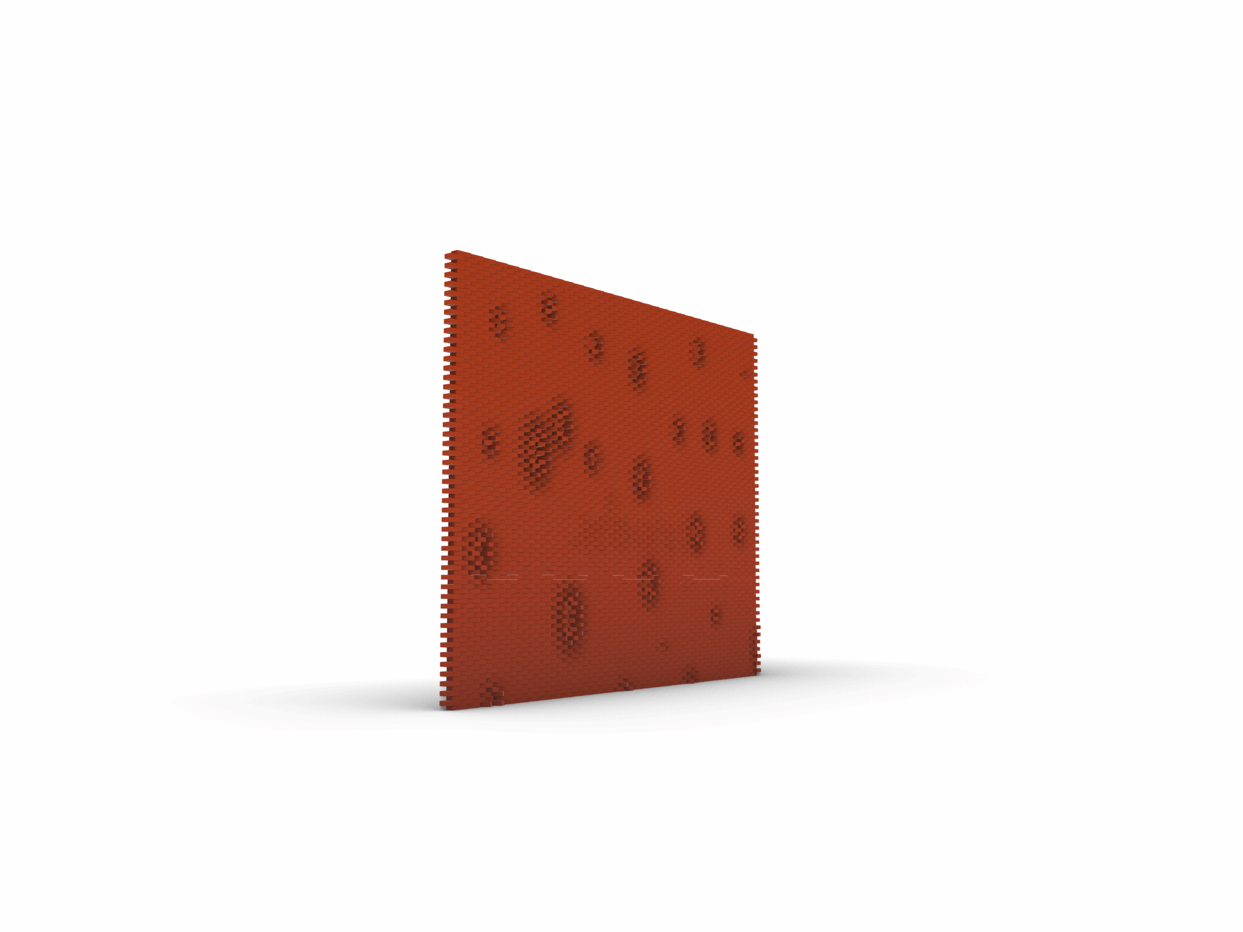
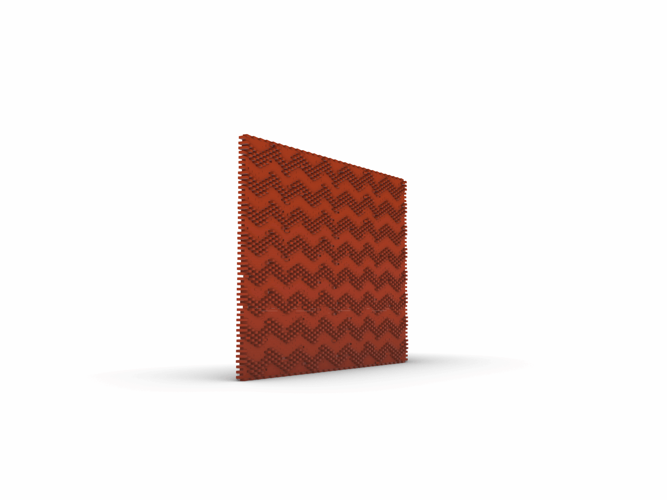
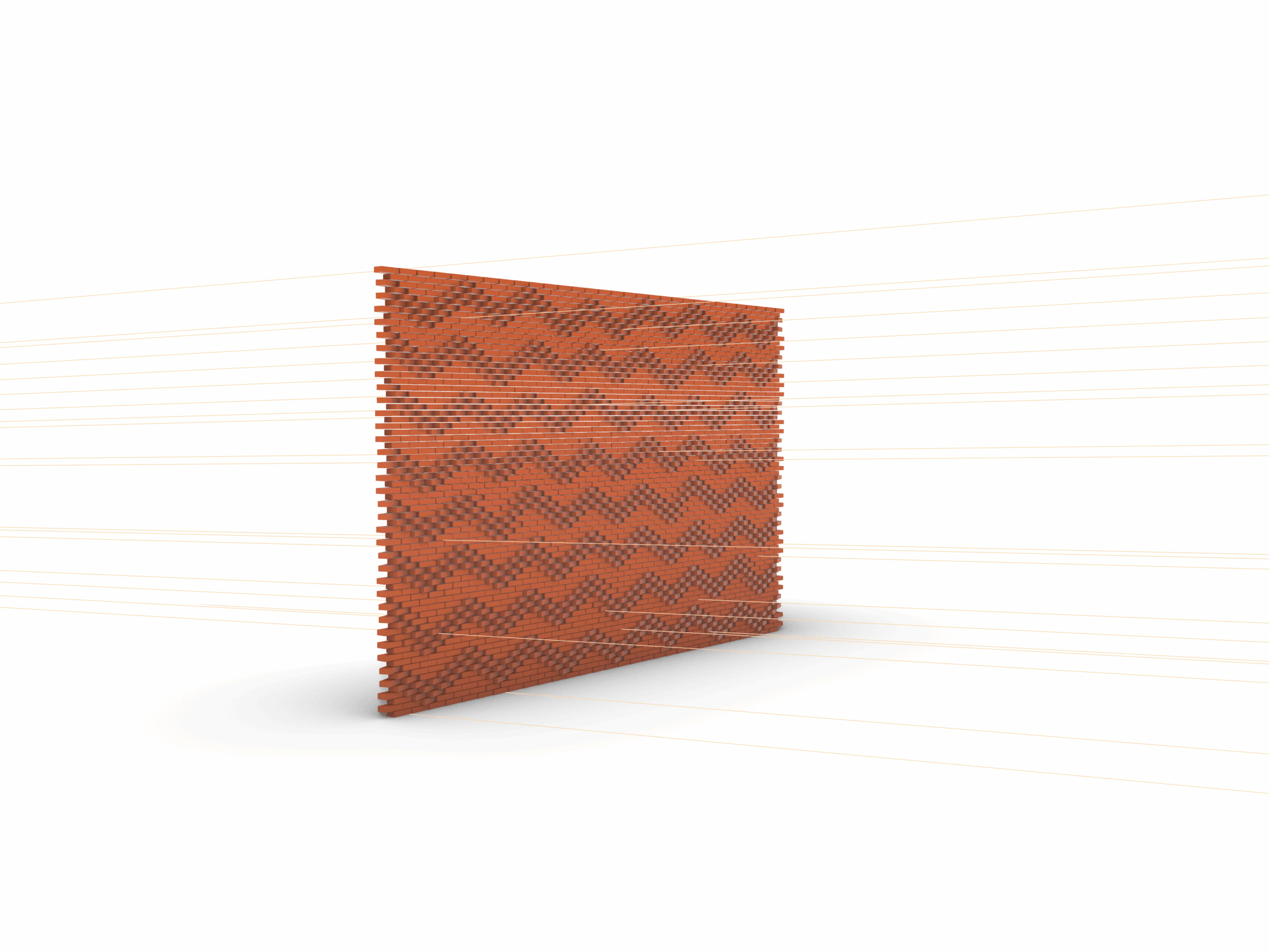
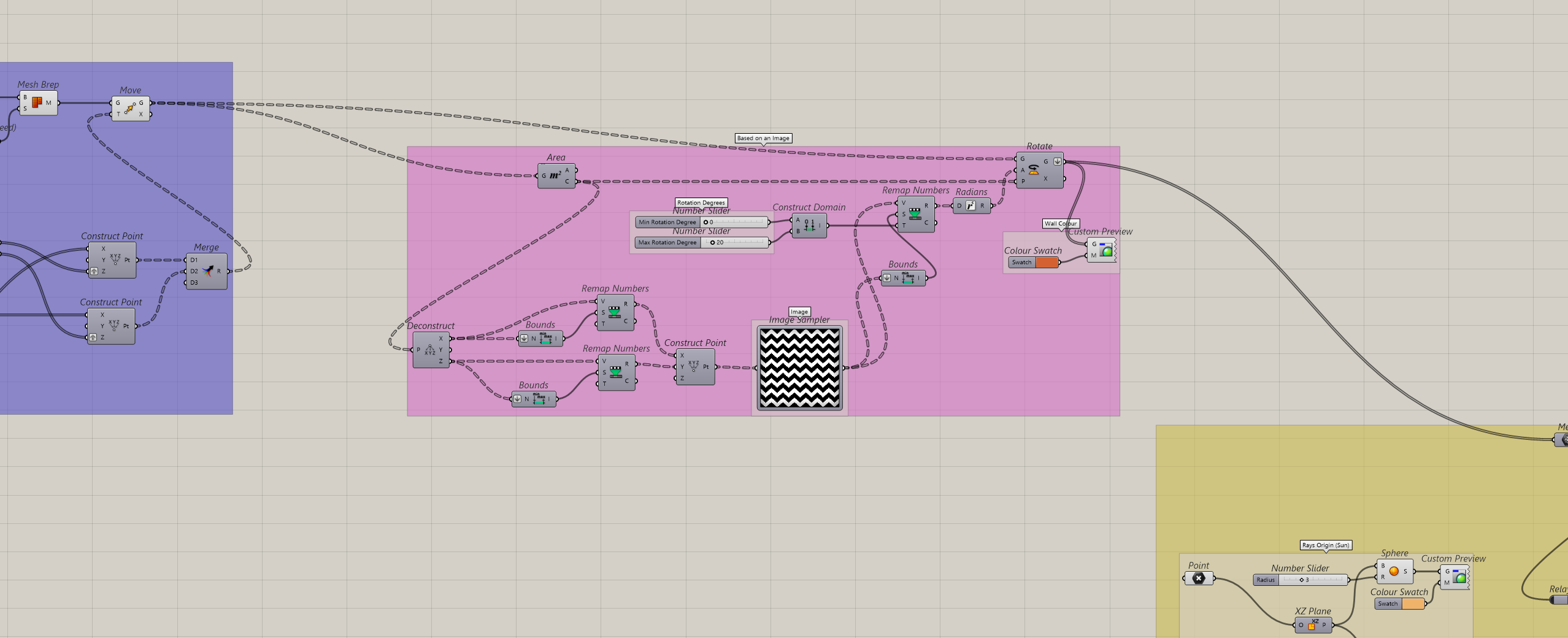
2.b Based on Image
This alternative script drives the brick rotation by sampling brightness or pixel values from an image pattern rather than a single point.
Center Identification: Area calculates the exact centroid of every single brick to establish individual local rotation axes.
UV Coordinate Mapping: Deconstruct and Remap break down the brick centroid into X and Y values, re-mapping them into a simply 0 to 1 domain via Construct Point to create a standard UV grid.
Pixel Value Extraction: Image Sampler feeds the normalized UV points into the image container, reading the specific color brightness or greyscale value at each corresponding brick location.
Domain Re-Mapping: Remap Numbers translates those raw distance values into a controlled angle range that can be adjustable, e.g. 0° to 180°, capturing the minimum and maximum extremes.
Angular Execution: Radians and Rotate convert the re-mapped degree values into radians, feeding them into the vector rotation component to dynamically twist the wall geometry aroun each local centroid.

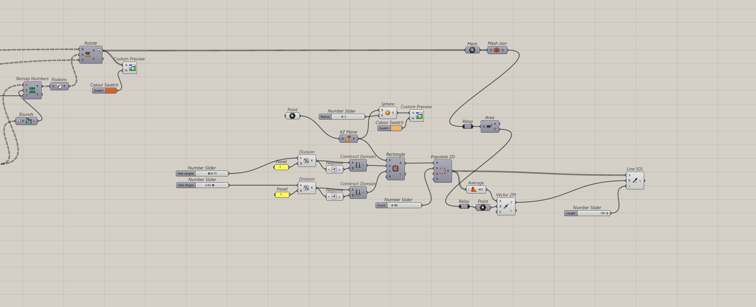
3. Vector Collisioning
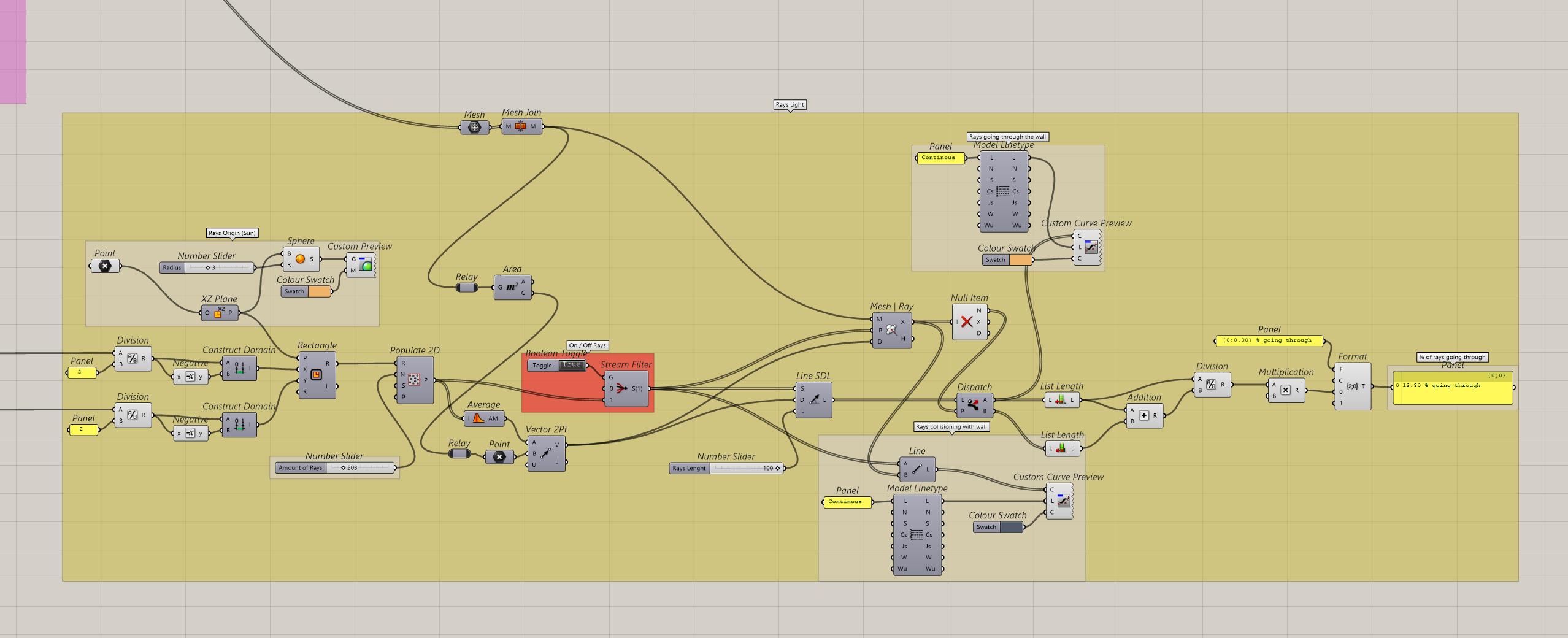
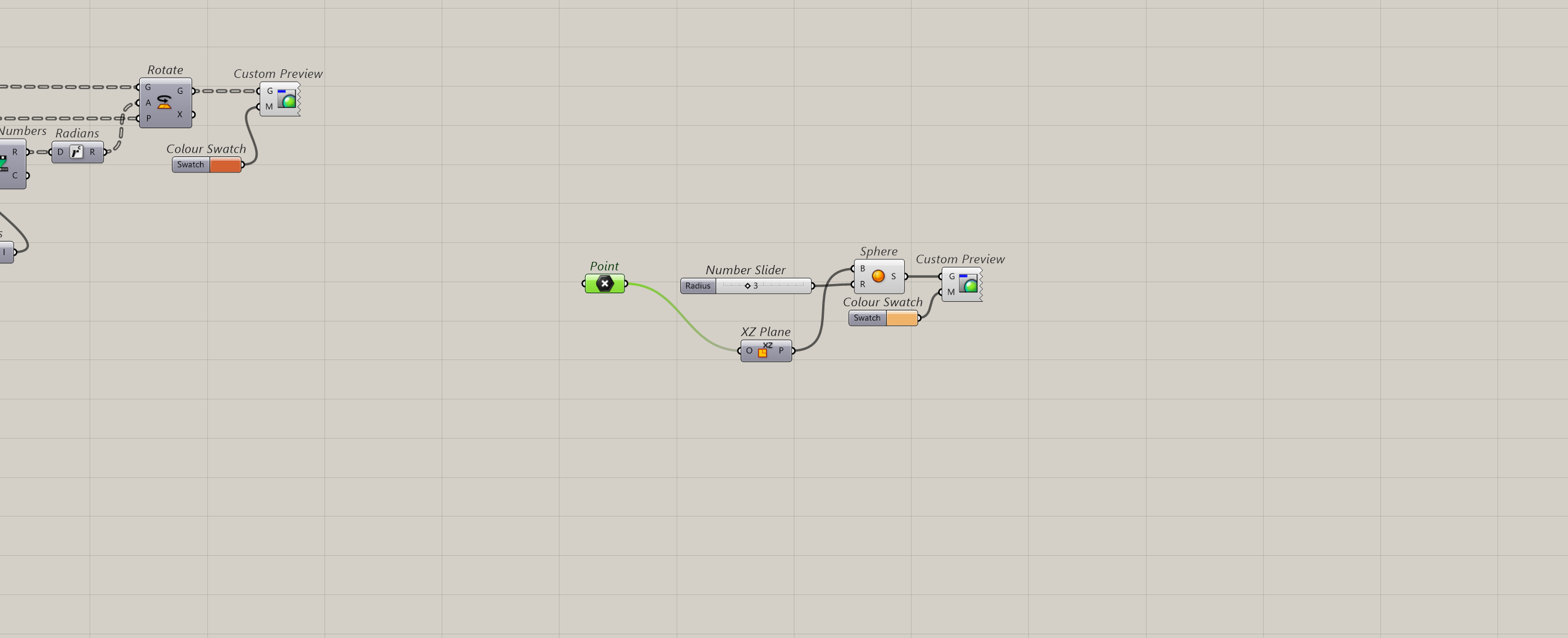
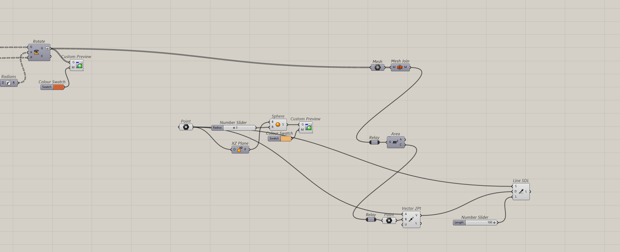
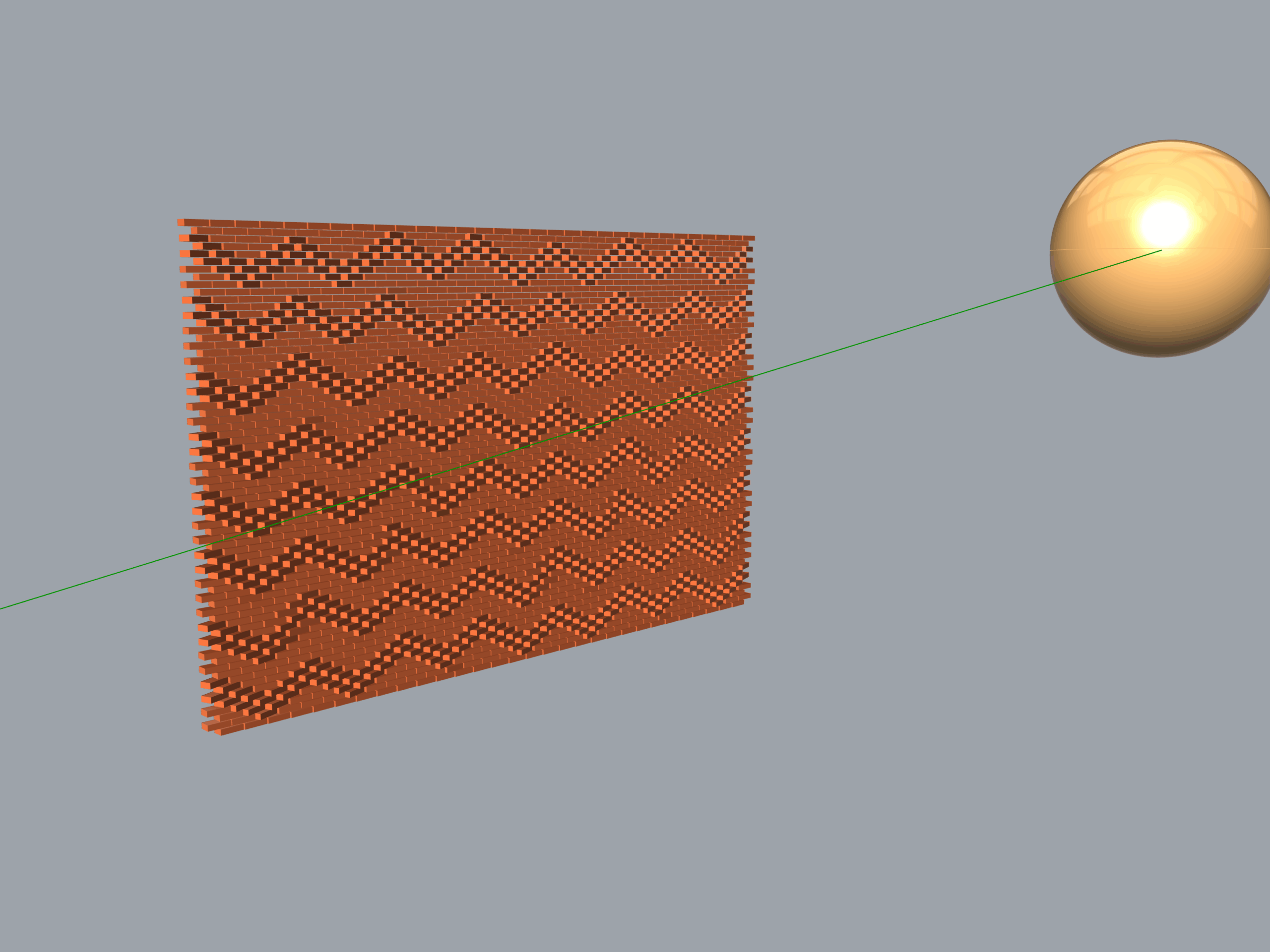
3.1 Vector Origin (Illuminance source)
This block establishes the geometric origin of the solar analysis engine, representing the sun or light source location.
Source Positioning: Point sets an interactive coordinate in space to acts as the focal center for the sunray vector origins.
Orientation Plane: XZ Plane anchors a working plane onto the light point, ensuring the calculation engine aligns with the vertical facade orientation.
Volume Representation: Sphere generates a physical 3D sphere at the light source location, controlled dynamically by a Number Slider to alter its size preview.
Visual Anchor: Custom Preview: Colors the sphere to give a clear hight constrast visual cue of the sun’s position within the Rhino viewport.
3.2 Sunray vector creation
Facade Unification: Mesh and Mesh Join convert the collection of rotated bricks into a standard mesh data and bakes them into a single continous entity, the Mesh Join creates a unifid solid target for raycasting.
Target Point Extraction: Area evaluates the entire unified mesh structure to find its absolute geometric center serving as the core target for the solar analysis.
Vector Direction: Vector 2Pt constructs a collection of directional paths by linking the sun’s coordinate poin ‘Point A’ straight to the facade’s absolute center poin ‘Point B’.
Ray Projection: Line SDL generates physical projection lines starting from the light source traveling along the created vector path direction with an analytical length controlled by a Number Slider.
3.3 Vector Multiplication
Emission Domain: Rectangle uses the Wall Length and Wall Height sliders from the Basic Wall Parameters to construct a centerd numeric domain. This sets up a licalized plane boundary positioned right at the sun’s location XZ Plane.
Ray Multiplication: Populate 2D scatters a precise random array of emission points across the newly created rectangle domain. A Number Slider for the Amoun of Rays controls exactly how many individual sunrays are generated for the analysis.
Vector Averaging: Average and Vector 2Pt evaluate the scattered emission points alongside the source point. The data flows into a Vector 2Pt component translating the coordinates into a unified direcional matrix poointing cleanly toward the facade’s center point.
Raycast Array Creation: Line SDL feeds the multiplied emission points into the start input and maps the calculated directional paths to the directional input. A number slider sets the projection length, shooting the finalized raycast vector array straight at the brick wall.
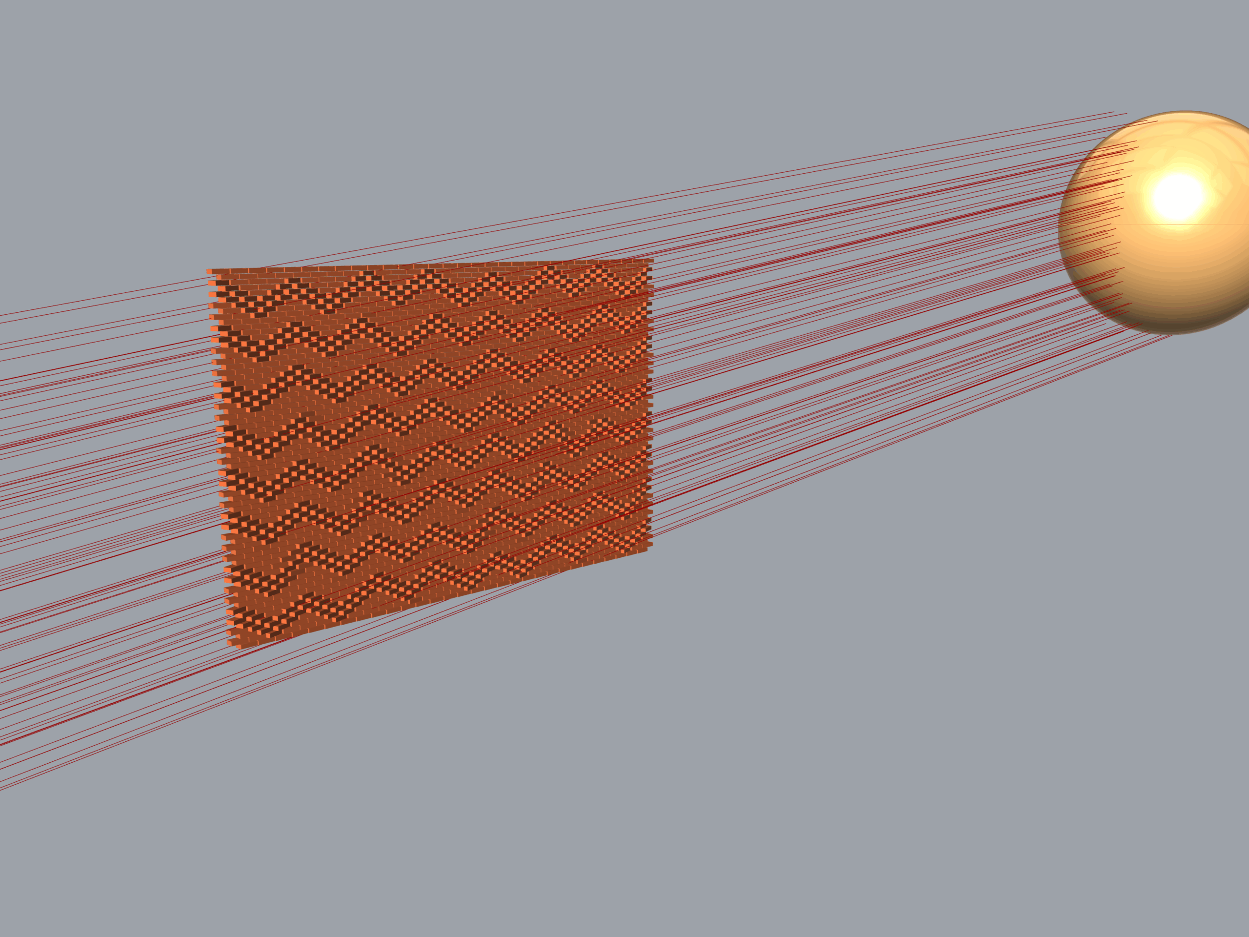
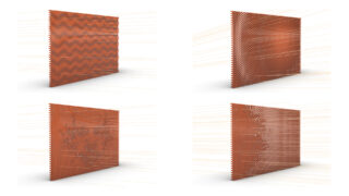
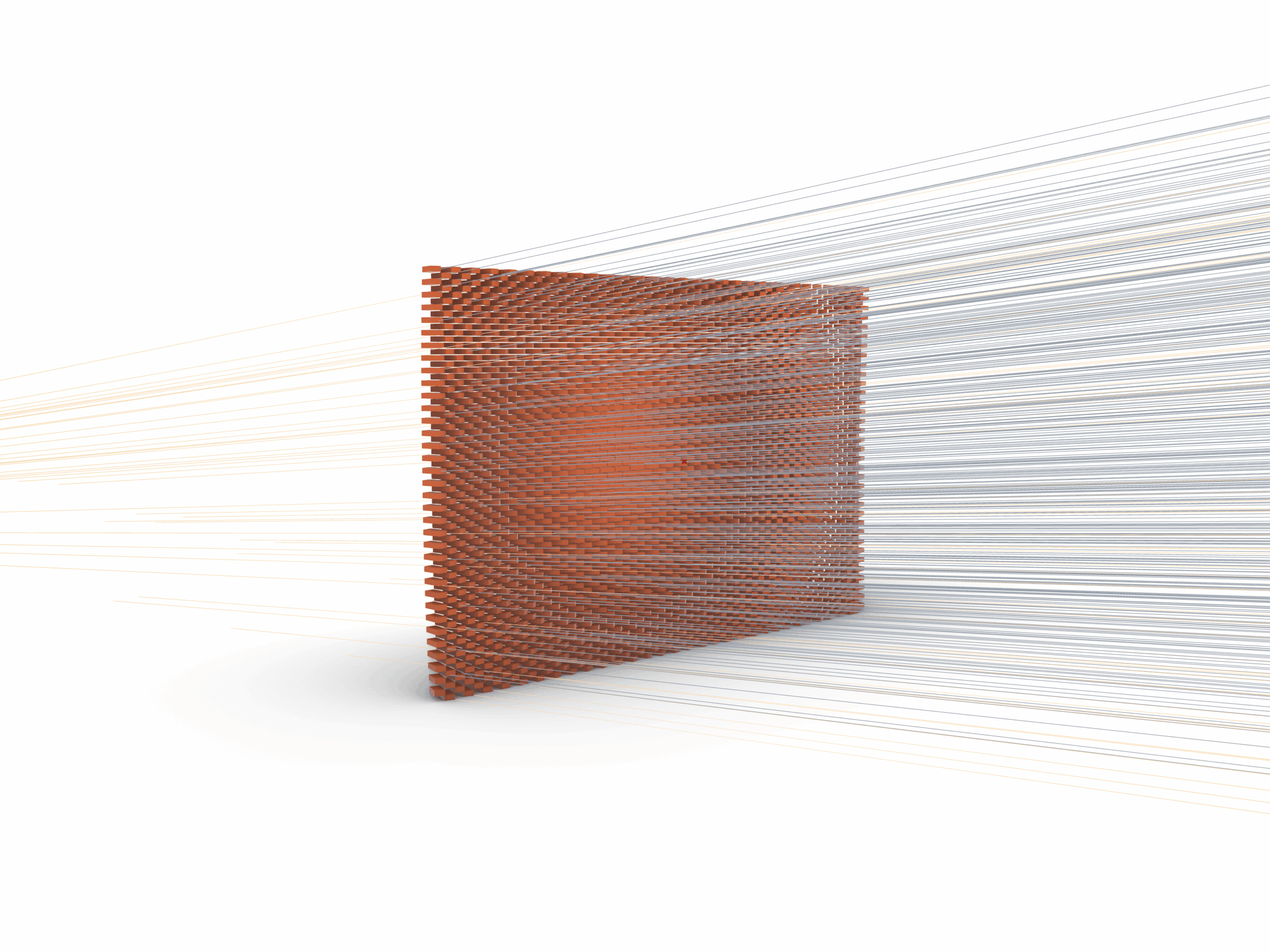
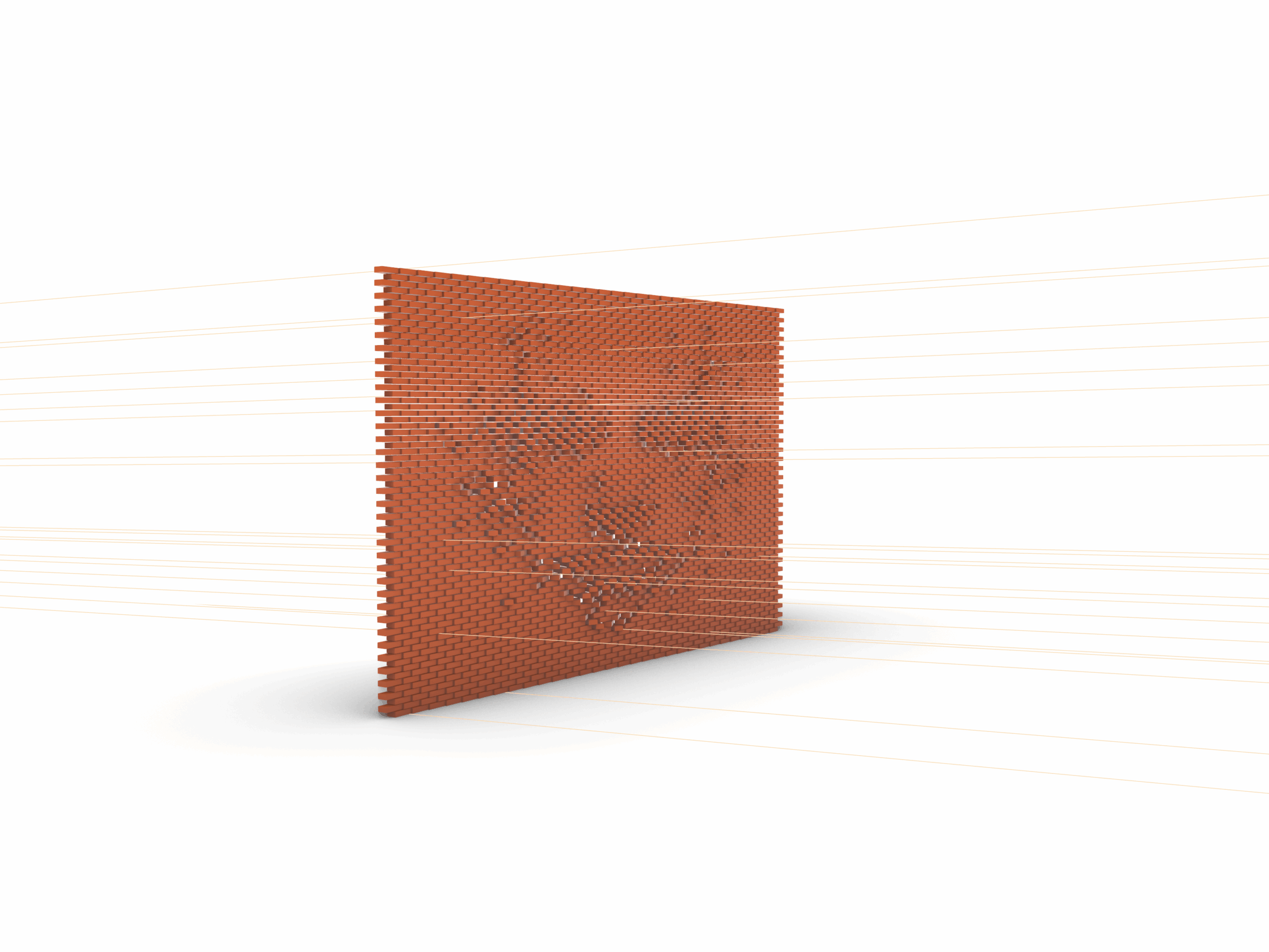
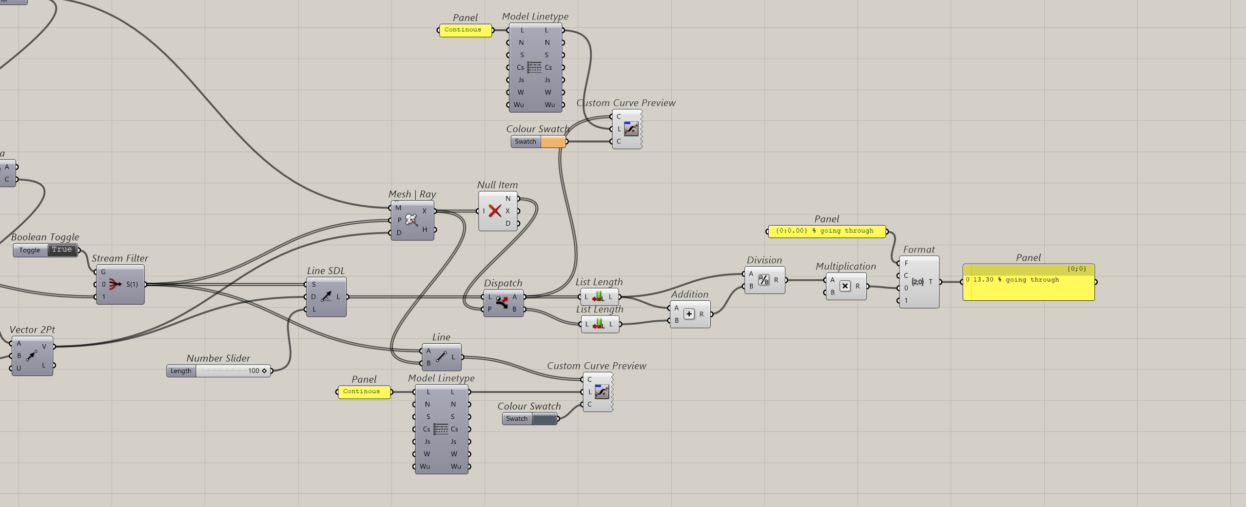
3.4 Rays Collision Detection
Intersection Engine: Mesh Ray casts the generated solar vectors against the unified brick mesh, identifying the exact X, Y, Z coordinates where intersections occur.
Data Cleansing: Null Item filters out empty values from vectors that missed the wall completely isolating the successful impact points.
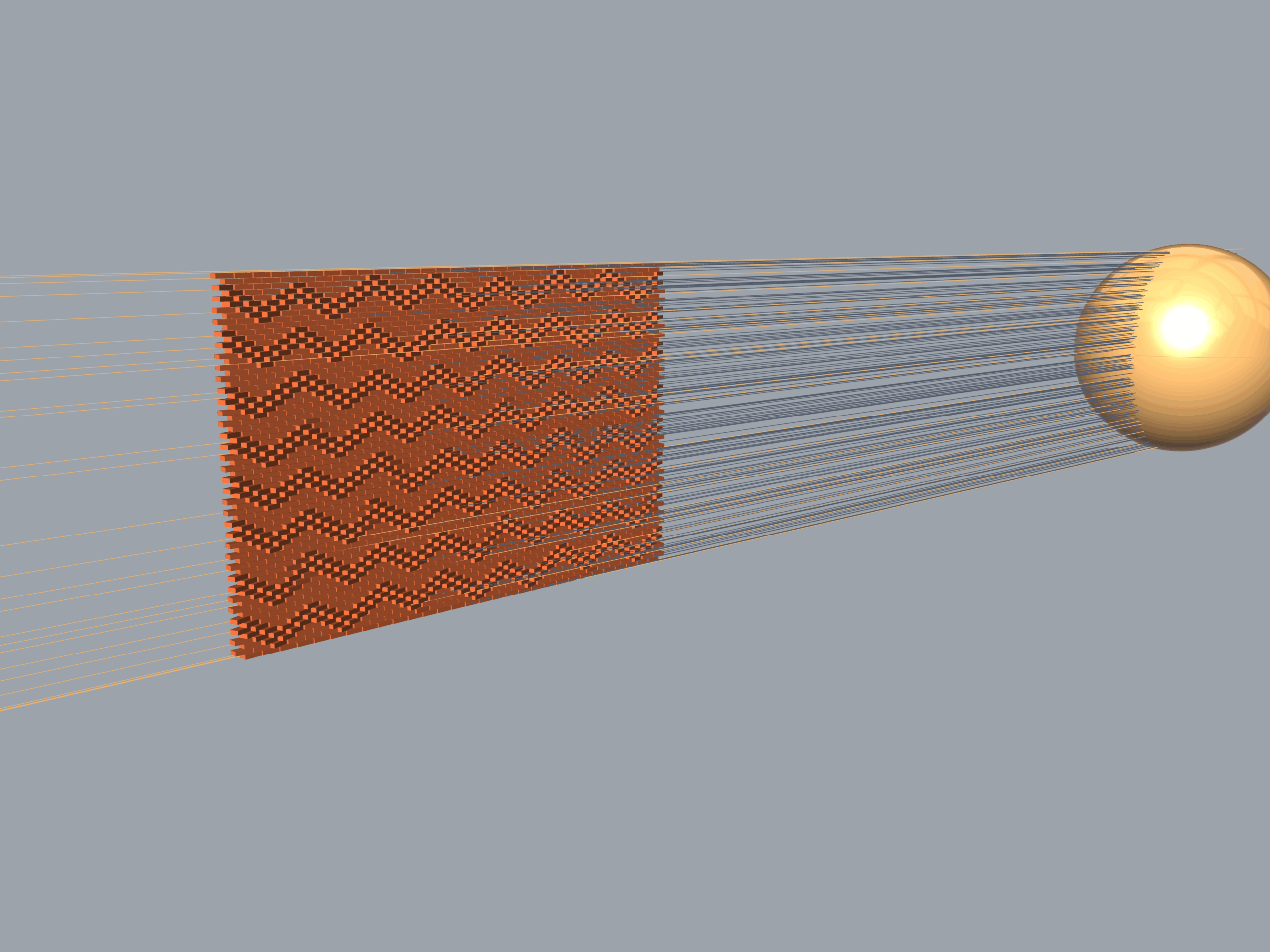
Stream Splitting: Dispatch separates the original light lines into two clean data sets: ‘Output A’ for rays passing unobstructed through the gaps, and ‘Output B’ for rays blocked by the brickwork.
Ray Truncation: Line reconstructs the blocked rays by connecting their original starting points directly to ther exact Mesh Ray collision points stopping the visual lines precisely at the brick surface.
Rays Preview: Custom Curve Preview sets the linetype and colour of the two different rays. Blue colour for the ones blocked and yellow colour for the rays unobstructed.
Performance Analytics: Division and Format quantify permeability by dividing the passing ray count by the total generated count. The final value passes through a text template to display a clean, real-time readout in percentage format.
Grasshopper File
Tutorial made by Leonardo Zapata.