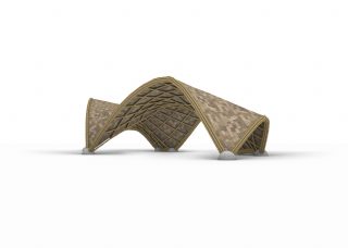
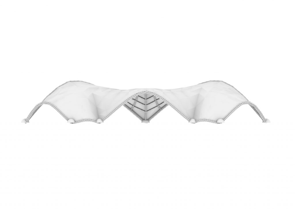
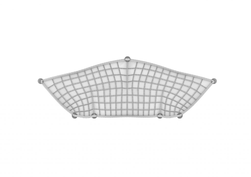
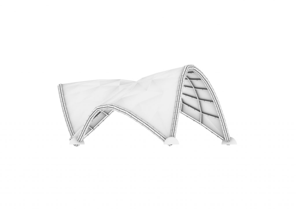
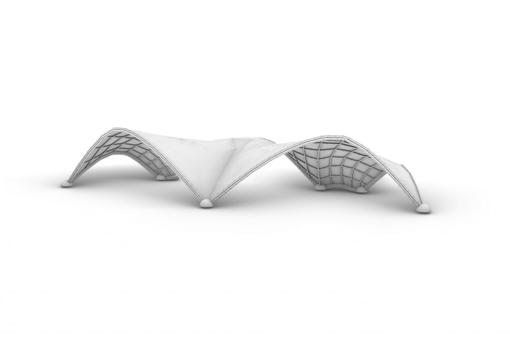
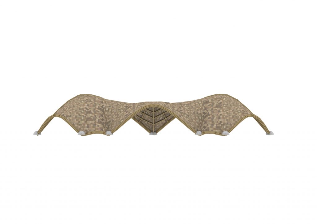
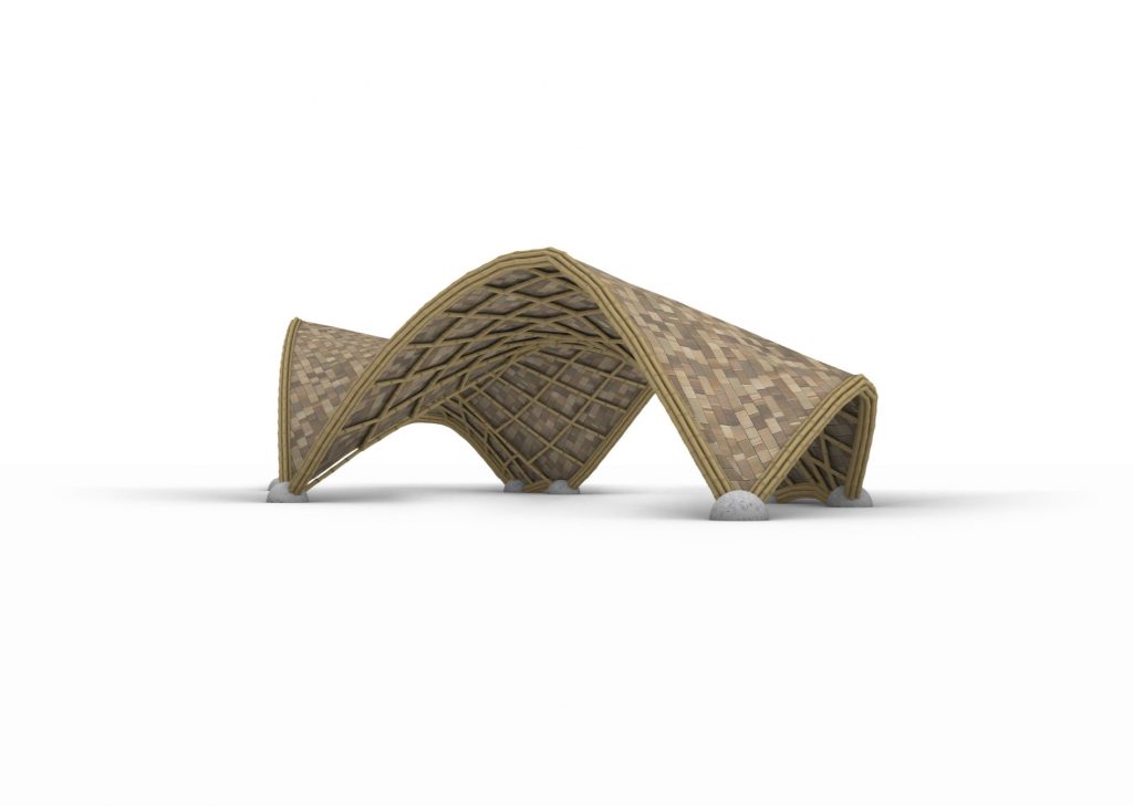
In recent years, bamboo structures have gained significant attention in architectural and engineering circles due to their sustainability, strength, and aesthetic appeal. Bamboo, known for its rapid growth and renewability, offers an eco-friendly alternative to conventional building materials. One particular application of bamboo in architectural design is the creation of gridshell structures, which utilize the inherent flexibility of bamboo to form elegant and efficient curved surfaces.
In this tutorial, we will explore the fundamentals of designing a bamboo gridshell structure using Grasshopper with Rhino. Through a series of step-by-step instructions, I will guide you in creating a simple yet captivating bamboo gridshell, demonstrating the potential of parametric design in architectural exploration and ecological innovation.
STEP 1: Polygon
Objective: Create the base plan for the gridshell using a polygon shape.
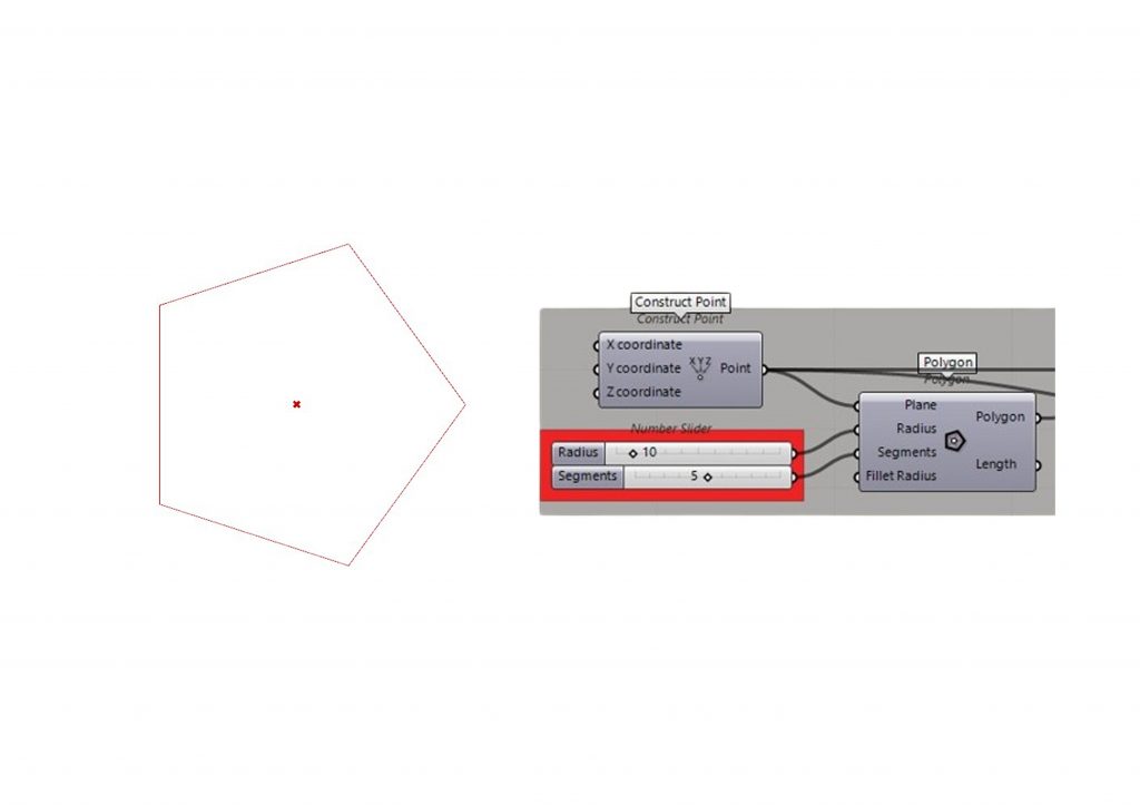
Constructing the Base Polygon:
- Use the “Construct Point” component to define the center point of the polygon. This can be done by specifying the X, Y, and Z coordinates or by connecting a point in Rhino to the component.
- Utilize the “Polygon” component to generate a polygon shape around the center point. Connect the center point to the “Polygon” component’s center input.
- Adjust the parameters of the polygon, such as the number of segments and the radius, using “Number Slider” components. Connect these sliders to the corresponding inputs of the “Polygon” component.
- Experiment with different values for the number of segments and the radius to achieve the desired shape and dimensions for the base plan.
Step 2: Transform Polygon
Objective: Rotate and scale the base polygon to further refine its shape.
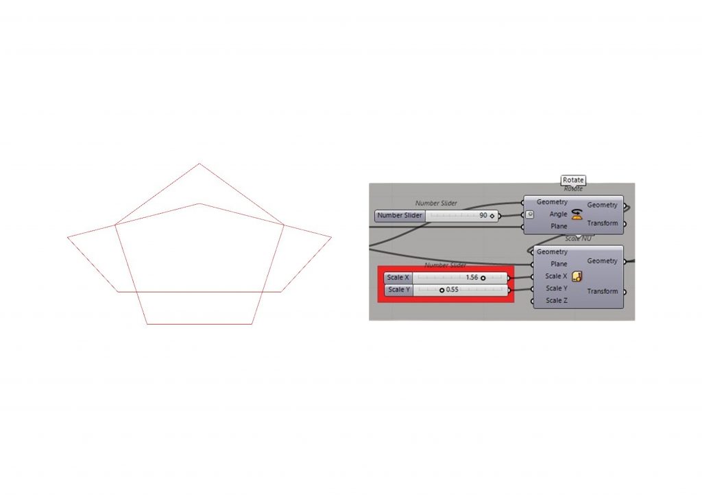
Rotating the Polygon:
- Use the “Rotate” component to rotate the base polygon shape. Connect the output of the “Polygon” component from Step One to the “Rotate” component’s geometry input.
- Utilize a “Number Slider” component to control the desired rotation angle in degrees. Connect the slider to the “Rotate” component’s angle input.
- Experiment with different rotation angles to achieve the desired orientation of the polygon shape.
Scaling the Polygon:
- Introduce the “Scale NU” (Non-Uniform Scale) component to scale the rotated polygon shape non-uniformly.
- Connect the output of the “Rotate” component to the “Scale NU” component’s geometry input.
- Use “Number Slider” components to control the scaling factors along the X and Y axes. Connect these sliders to the “Scale NU” component’s ScaleX and ScaleY inputs.
- Adjust the values of the sliders to modify the shape of the polygon. Increasing or decreasing the scaling factors alters the dimensions of the polygon along the respective axes.
STEP 3: Refine Mesh
Objective: Refine the geometry of the polygon shape by converting it into a mesh and adjusting its density.
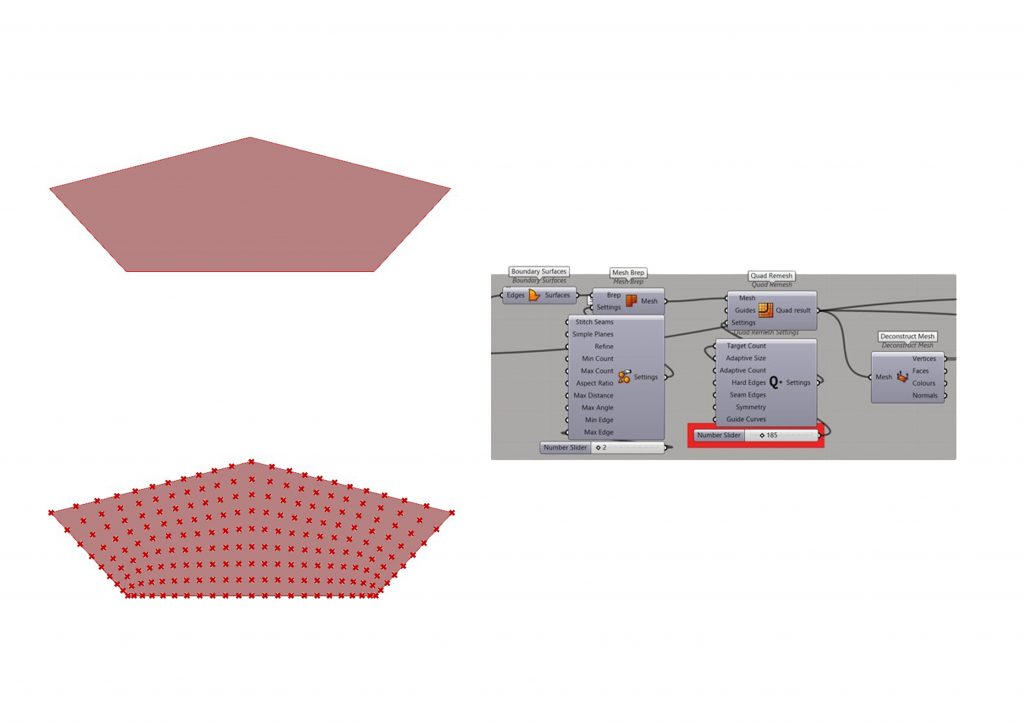
Creating Boundary Surfaces:
- Utilize the “Boundary Surfaces” component to create a surface from the polygon geometry. Connect the output of the transformed polygon from Step Two to the “Boundary Surfaces” component’s input.
- This step ensures that the polygon shape is converted into a closed surface suitable for meshing.
Meshing the Surface:
- Connect the output of the “Boundary Surfaces” component to a “Mesh Brep” component to convert the surface into a mesh representation.
- Use the “Settings (Custom)” component to customize the meshing parameters. Add a “Number Slider” component to control the maximum edge length of the mesh. Connect the slider to the “Settings (Custom)” component’s MaxEdge input.
- Adjust the value of the slider to control the level of mesh refinement. Smaller values result in a denser mesh, while larger values produce a coarser mesh.
Quad Remeshing:
- Connect the output of the “Mesh Brep” component to the “Quad Remesh” component to further refine the mesh topology.
- Use the “Quad Remesh Settings” component to adjust the target quad count of the remeshed mesh. Add a “Number Slider” component to control the target quad count and connect it to the “Quad Remesh Settings” component’s TargetCount input.
- Experiment with different values for the target quad count to achieve the desired level of mesh detail.
Deconstructing the Mesh:
- Connect the output of the “Quad Remesh” component to a “Deconstruct Mesh” component to extract the vertices, edges, and faces of the refined mesh.
- This step prepares the refined mesh for further manipulation or analysis in Grasshopper.
STEP 4: Anchors
Objective: Define anchor points on the refined mesh to establish fixed positions for the gridshell structure.
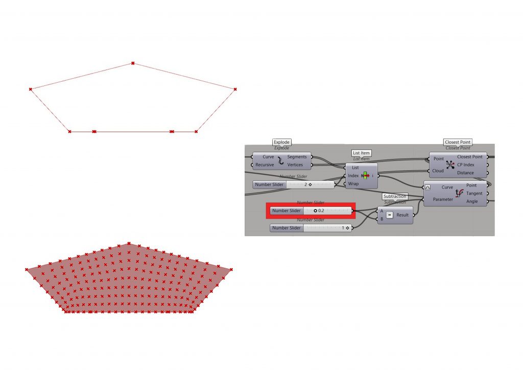
Exploding the Mesh:
- Use the “Explode” component to break down the refined mesh into its constituent vertices. Connect the output of the refined mesh from Step Three to the “Explode” component’s input.
- This step separates the vertices of the mesh, allowing us to manipulate them individually.
Selecting Anchor Points:
- Connect the output of the “Explode” component to a “List Item” component to select specific vertices from the list of vertices. Add a “Number Slider” component to control the index of the vertex to be selected, and connect it to the “List Item” component’s index input.
- This step allows us to choose which vertices will serve as anchor points based on their index in the list.
Evaluating Curve Parameters:
- Connect the output of the “List Item” component to an “Evaluate Curve” component. This component evaluates a curve at a specific parameter value. Connect the result of the “Evaluate Curve” component to the “B” input of a “Subtraction” component.
- Use “Number Slider” components to define the parameters for the “Evaluate Curve” component. These sliders control the parameter values used to evaluate the curve, allowing us to adjust the position of the anchor points along the mesh.
Finding Closest Points:
- Utilize the “Closest Point” component to find the closest points on the refined mesh to the evaluated curve points. Connect the output “Vertices” of the “Explode” component with input of the “Closest Point” component.
- Connect the output of the “Deconstruct Mesh” component from Step Three to the “Cloud” input ,,Point´´ of the “Closest Point” component.
- This step establishes a correspondence between the anchor points defined by the evaluated curve and the closest vertices on the mesh.
STEP 5: Kangaroo
Objective: Implement the Kangaroo physics engine to simulate the behavior of the gridshell structure under various loads and constraints.

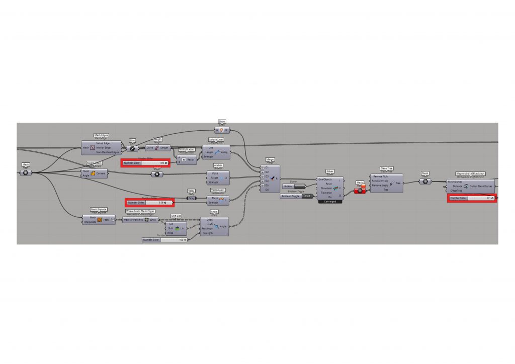
Mesh Preparation:
- Connect the output of the refined mesh from Step Three to a “Mesh” component. Ensure that the mesh is properly prepared for Kangaroo physics simulation.
Extracting Mesh Features:
- Utilize components such as “Mesh Edges”, “Mesh Corners”, and “Mesh Explode” to extract various features of the mesh, such as edges and vertices, necessary for further manipulation and analysis.
- Customize the settings of these components based on the provided image or specific requirements
Merging Mesh Features:
- Connect the outputs of the “Mesh Edges”, “Mesh Corners”, and “Mesh Explode” components to a “Merge” component. This step consolidates the extracted mesh features into a single entity, preparing them for Kangaroo physics simulation.
Kangaroo Physics Simulation Setup:
- Connect the output of the “Merge” component to a “Kangaroo Solver” component. This component will handle the physics simulation.
- Utilize the “Button” component and a “Boolean Toggle” component to control the initiation of the Kangaroo simulation.
- Customize the settings of the Kangaroo Solver component based on the desired simulation parameters.
Mesh Cleaning:
- Connect the output of the Kangaroo Solver component to a “Clean Tree” component. This step ensures that the data structure of the mesh is properly organized for further processing.
Offsetting Mesh with WeaveBirds:
- Connect the output of the “Clean Tree” component to a “WeaverBirds Offset Mesh” component.
- Use a “Number Slider” component to control the distance for the offset.
- Adjust the settings of the WeaverBirds Offset Mesh component as needed based on the provided image or specific requirements.
STEP 6: Foundation
Objective: Create a foundation for the gridshell structure by cutting a spherical volume from the ground surface.
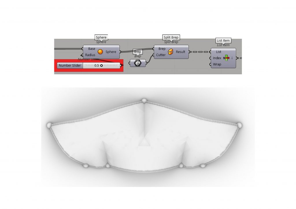
Creating a Spherical Volume:
- Use the “Sphere” component to generate a spherical volume representing the foundation. Connect the “Base” input of the “Sphere” component to the output of the “Closest Point” component from Step Four, ensuring that the center of the sphere aligns with the anchor point selected in Step Four.
- Connect a “Number Slider” component to control the radius of the sphere. Adjust the slider to set the desired radius for the foundation.
Cutting the Ground Surface:
- Connect the output of the ground surface from earlier steps to the “Brep” input of a “Split Brep” component.
- Connect the output of the sphere to the “Cutter” input of the “Split Brep” component. This will define the cutting geometry.
- The “Split Brep” component will create two output surfaces: one representing the portion of the ground surface inside the spherical volume and the other representing the portion outside.
Customization:
- Adjust the radius of the spherical volume using the “Number Slider” component to match the desired size of the foundation.
- Consider the placement of the foundation on the ground surface and adjust the position of the sphere’s center accordingly.
Extracting the Cut Surface:
- Use a “List Item” component to select the surface representing the portion of the ground surface inside the spherical volume.
- Connect the output of the “Split Brep” component to the “List” input of the “List Item” component. This will extract the desired surface from the list of split surfaces.
STEP 7: Lidi Bundles
Objective: Generate lidi bundles along the edges of the mesh structure to enhance its structural integrity.
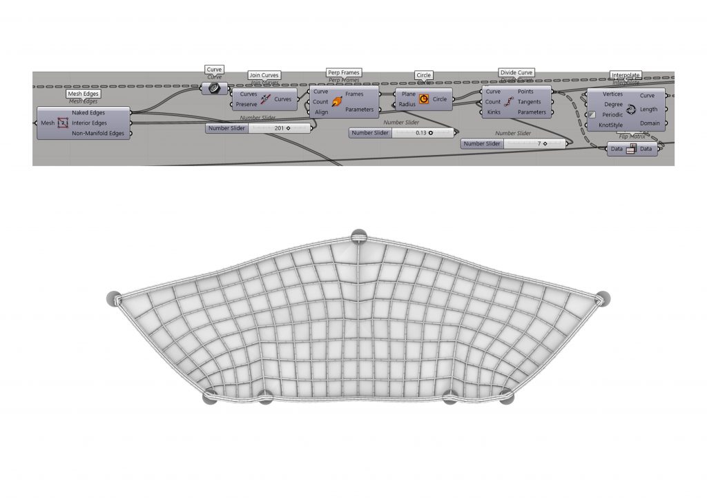
Extracting Mesh Edges:
- Use the “Mesh Edges” component to extract the edges of the mesh structure from Step Five.
- Connect the output of the “Mesh Edges” component to the “Edges” input of the “Mesh” component from Step Five.
Creating Curves Along Edges:
- Utilize the “Curve” component to generate curves along the mesh edges. Connect the output of the “Mesh” component to the “Curves” input of the “Curve” component.
- Join the individual curves into a single continuous curve using the “Join Curves” component.
- Connect the output of the “Join Curves” component to the “Curves” input of the “Perp Frames” component.
Generating Perpendicular Frames:
- Use the “Perp Frames” component to create perpendicular frames along the joined curves. Connect the output of the “Join Curves” component to the “Curves” input of the “Perp Frames” component.
- Adjust the number of frames using a “Number Slider” connected to the “Count” input of the “Perp Frames” component.
Creating Circles at Frame Points:
- Utilize the “Circle” component to generate circles at the frame points. Connect the output of the “Perp Frames” component to the “Frames” input of the “Circle” component.
- Adjust the radius of the circles using a “Number Slider”.
- Connect the output of the “Circle” component to the “Curve” input of the “Divide Curve” component.
Dividing Curves:
- Use the “Divide Curve” component to divide the curves into equal segments. Connect the output of the “Circle” component to the “Curve” input of the “Divide Curve” component.
- Adjust the number of divisions using a “Number Slider” connected to the “Count” input of the “Divide Curve” component.
Creating Interpolated Curves:
- Utilize the “Flip Matrix” component to reorganize the divided points. Connect the output of the “Divide Curve” component to the “List” input of the “Flip Matrix” component.
- Use the “Interpolate” component to generate interpolated curves through the reorganized points. Connect the output of the “Flip Matrix” component to the “Points” input of the “Interpolate” component.
STEP 8: Bamboo Visualization
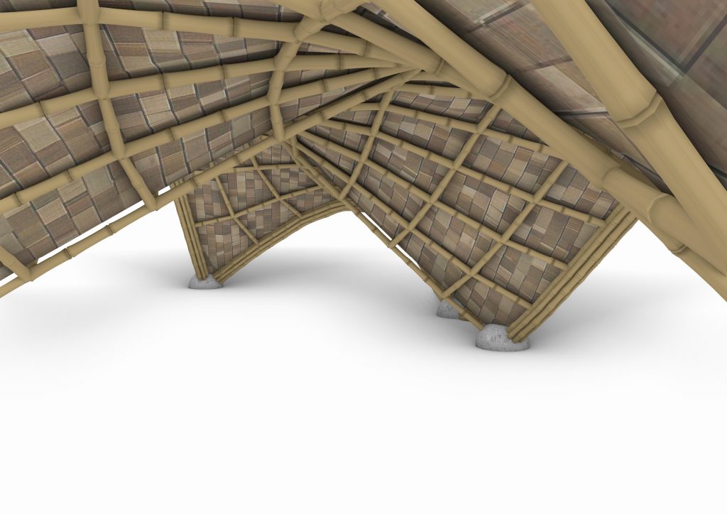
Objective: Visualize the bamboo poles within the gridshell structure using an internet-ready script. There are many of them, you can choose the one that you desire.
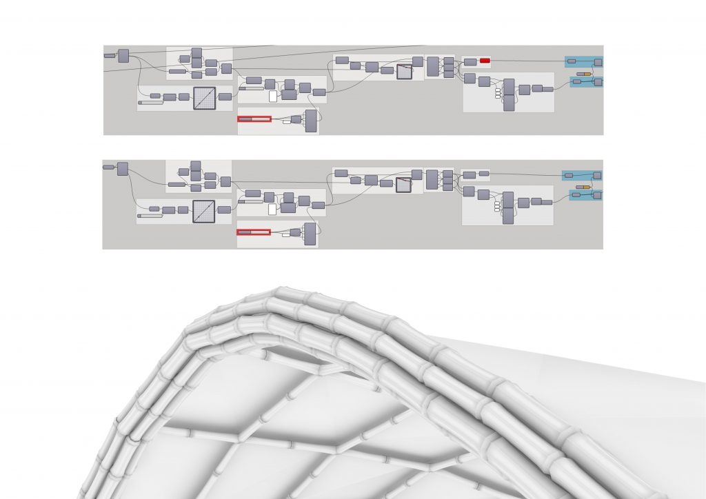
Connecting Inner Bamboo Grid:
- Connect the output of the “Mesh Edges” component from Step Seven to the “Interior Edges” input of the visualization script.
- This step visualizes and adjusts the inner bamboo grid within the structure.
Connecting Outer Bamboo Grid:
- Connect the output of the “Mesh Edges” component from Step Seven to the “Naked Edges” input of the visualization script.
- This step visualizes and adjusts the edges of the bamboo grid within the structure.
Executing the Visualization Script:
- Utilize the internet-ready script designed for visualizing bamboo poles within the gridshell structure.
- Ensure that the script is properly configured and compatible with Grasshopper.
- Execute the script to generate a visual representation of the bamboo poles within the gridshell structure.
STEP 9: Bake
Objective: Export the finalized geometry for further processing or visualization in external software.
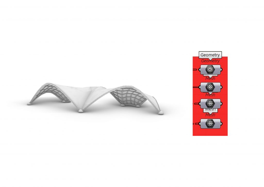
Geometry:
- Connect the output of the finalized geometry, likely represented by a “Geometry” component to a “List Item” component from Step Six.
- “Bake” the “Geometry” component.
- This step prepares the geometry for export by converting it into a format compatible with external software.
Offset Mesh:
- Connect the output of the “WeaverBirds Offset Mesh” component from Step Six to a new “Mesh” component.
- “Bake” the “Mesh” component.
- This step bakes the offset mesh generated in Step Six for further processing or visualization.
Baking Outer Bamboo Grid:
- Connect the output of the mesh representing the outer bamboo grid from Step Eight to a new “Mesh” component.
- “Bake” the “Mesh” component.
- This step bakes the outer bamboo grid geometry for export or visualization.
Baking Inner Bamboo Grid:
- Connect the output of the mesh representing the inner bamboo grid from Step Eight to a new “Mesh” component.
- “Bake” the “Mesh” component.
- This step bakes the inner bamboo grid geometry for export or visualization.
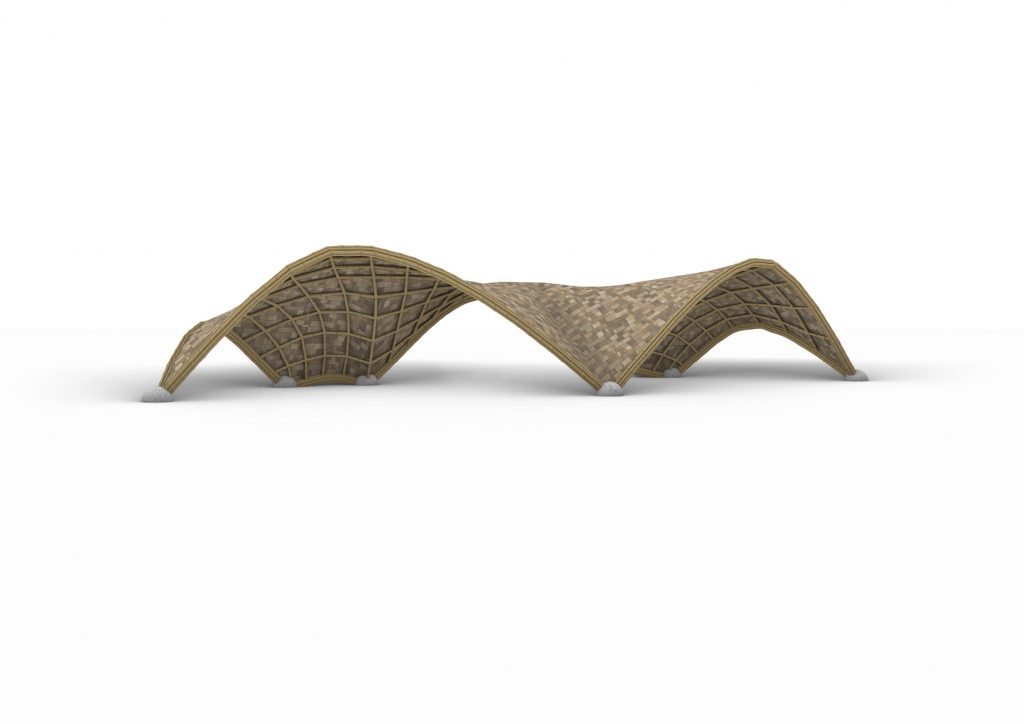
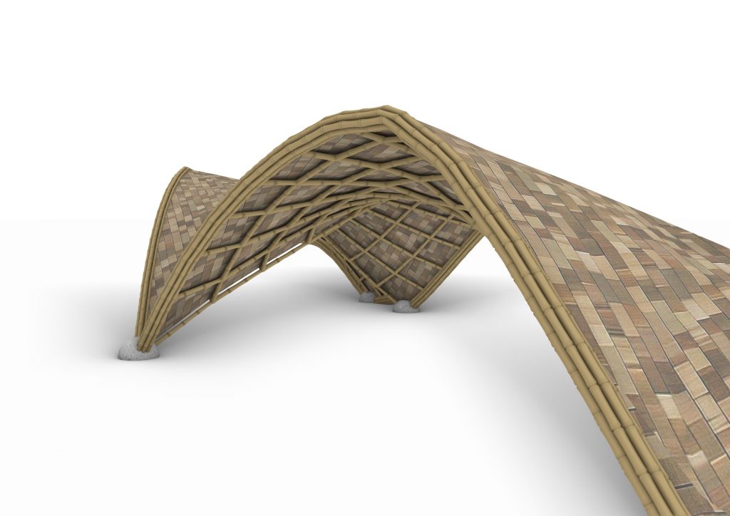
The weaknesses and benefits of the Grasshopper script for creating a bamboo gridshell structure:
Weaknesses:
Depending on the complexity of the structure and the computational power of the system, running the script might be resource-intensive and time-consuming. While the script allows for some customization through parameters and sliders, it may not accommodate all design variations or specific requirements. Certain functionalities of the script, such as offsetting meshes or mesh manipulation, rely on third-party plugins like WeaverBirds, which may not be available or compatible with all versions of Grasshopper.
Benefits:
The script offers a high degree of design flexibility, allowing users to create intricate gridshell structures with parametric controls. By automating the design and generation process, the script can significantly reduce the time and effort required to create complex gridshell structures compared to manual methods. The script facilitates visualization of the design in real-time, enabling designers to iteratively refine and optimize the structure based on visual feedback.
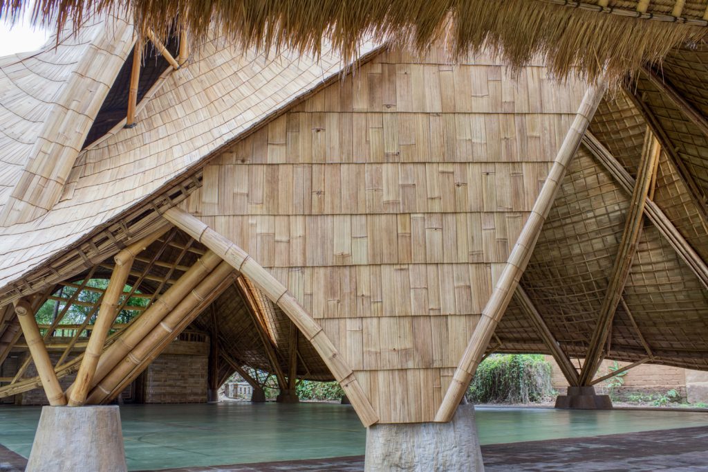
With increasing awareness of environmental concerns and the push towards sustainable development, the adoption of bamboo gridshell structures is expected to rise, paving the way for innovative and sustainable architectural designs worldwide.
