INSPIRATION
So many types of shapes, sizes, textures, colours… Nowadays, stairs do not only fulfill the function of overcoming height differences, but they also add creative and visual element to their surrounding area.
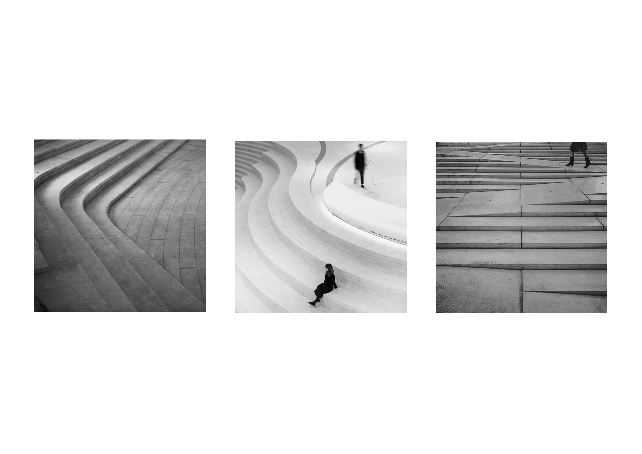
BACKGROUND
Stairs have been an integral part of human architecture for centuries, serving not only as a functional element but also as a canvas for artistic expression. The evolution of stair design has witnessed a fascinating transformation.
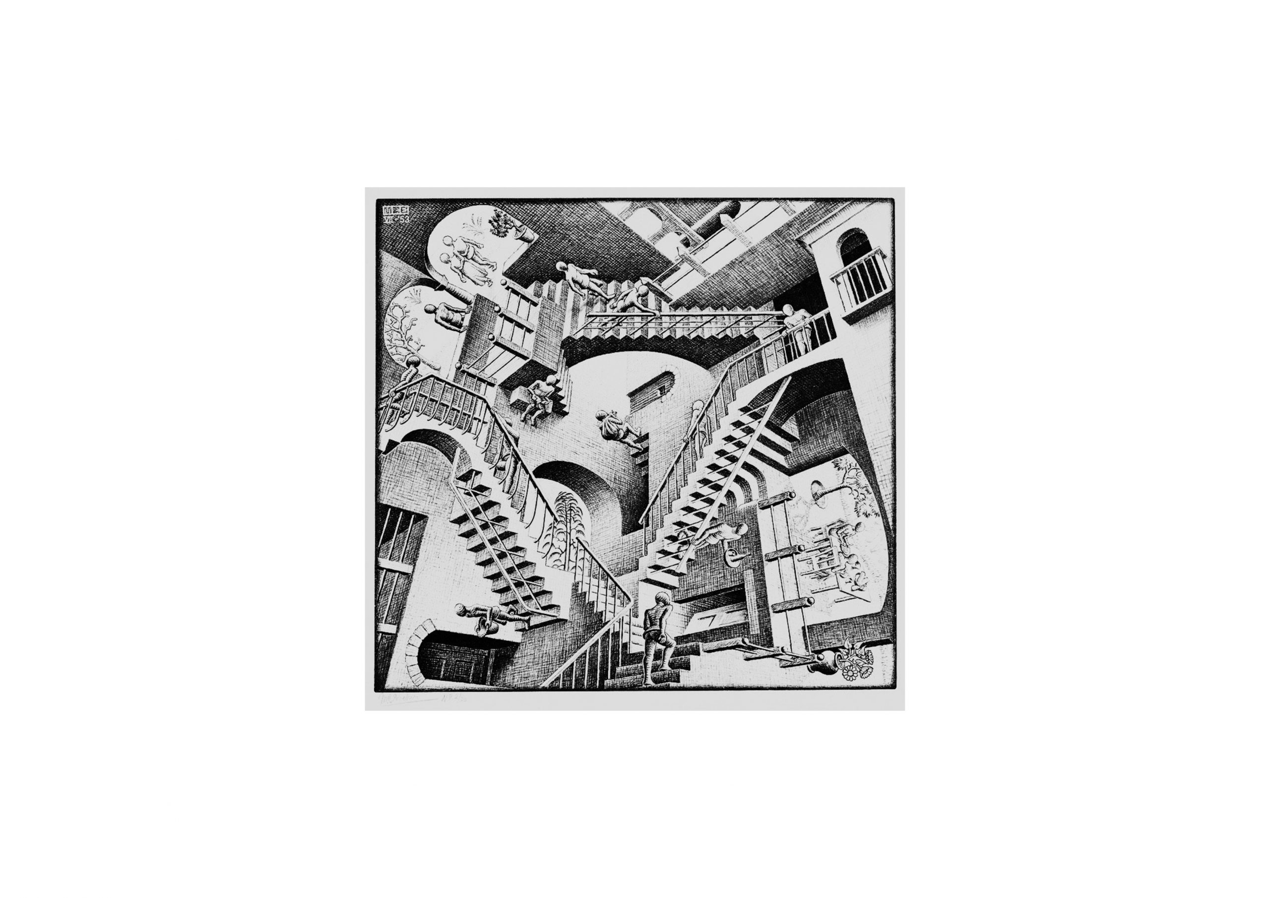
In the realm of visual arts, stairs have long been used to captivate the human mind. Artists and illustrators throughout history have recognized the inherent complexity of stairs, utilizing them to create optical illusions and challenges that engage the viewer’s perception.
The intricate illustrations of stairs planted the seeds of parametric thinking. These mind-bending staircases, defying traditional geometric norms, prompted architects and designers to explore unconventional forms and structures.
-illustration by Maurits Cornelis Escher named Relativity
GOAL
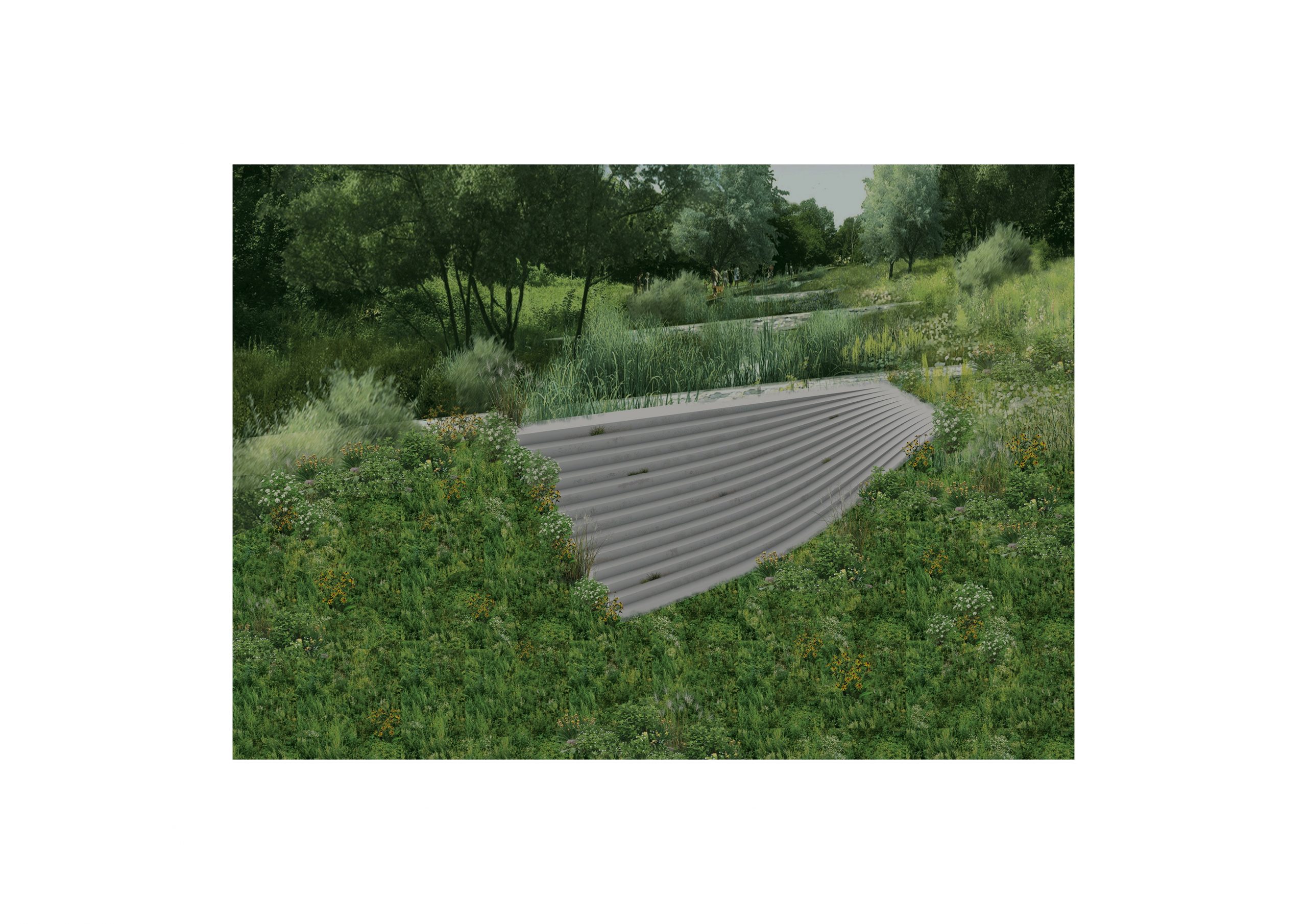
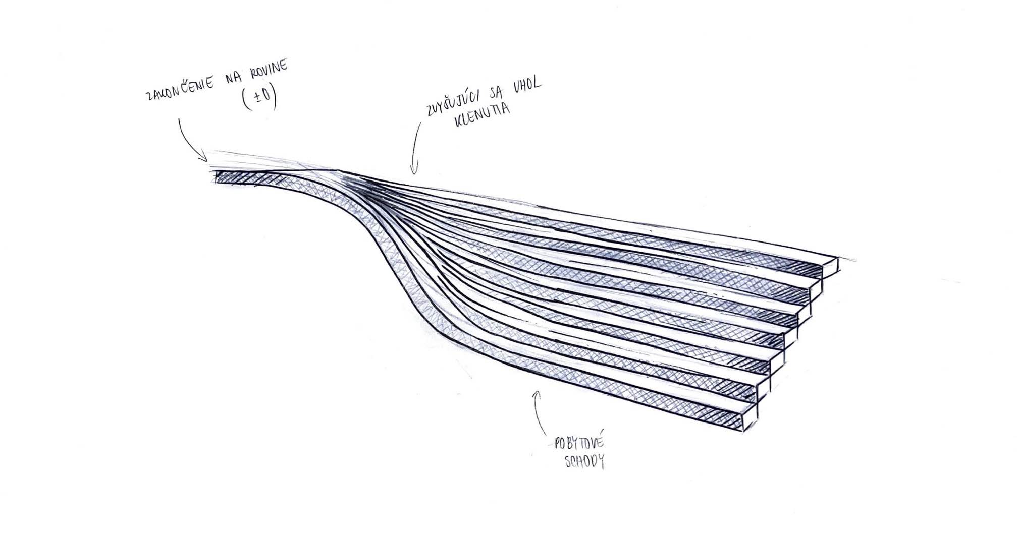
My idea was not to incorporate the fluidity into the stairs surface, but into their overall shape, creating a harmonic relationship between the organic mass and the external environment. Result? A pleasant public space embedded into your local sloped landscape area.
lllllllllllllllllll
llllllllllllll
SKETCH
TUTORIAL
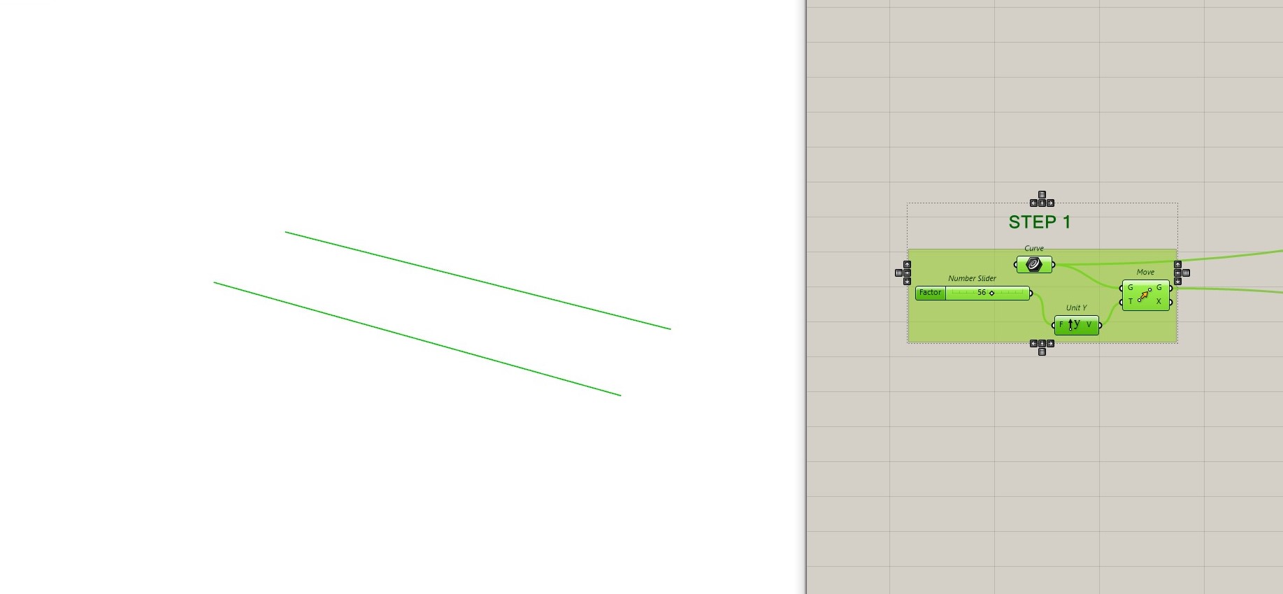
STEP 1
Draw a base line in the X-direction in Rhinoceros. Use the “Curve” component in Grasshopper to create a base curve and set.
Use the “Move” component to move the base curve and to create a unit vector in the Y-direction adjusting it with a number slider. This slider will control the depth of each stair and overall depth of the whole staircase.
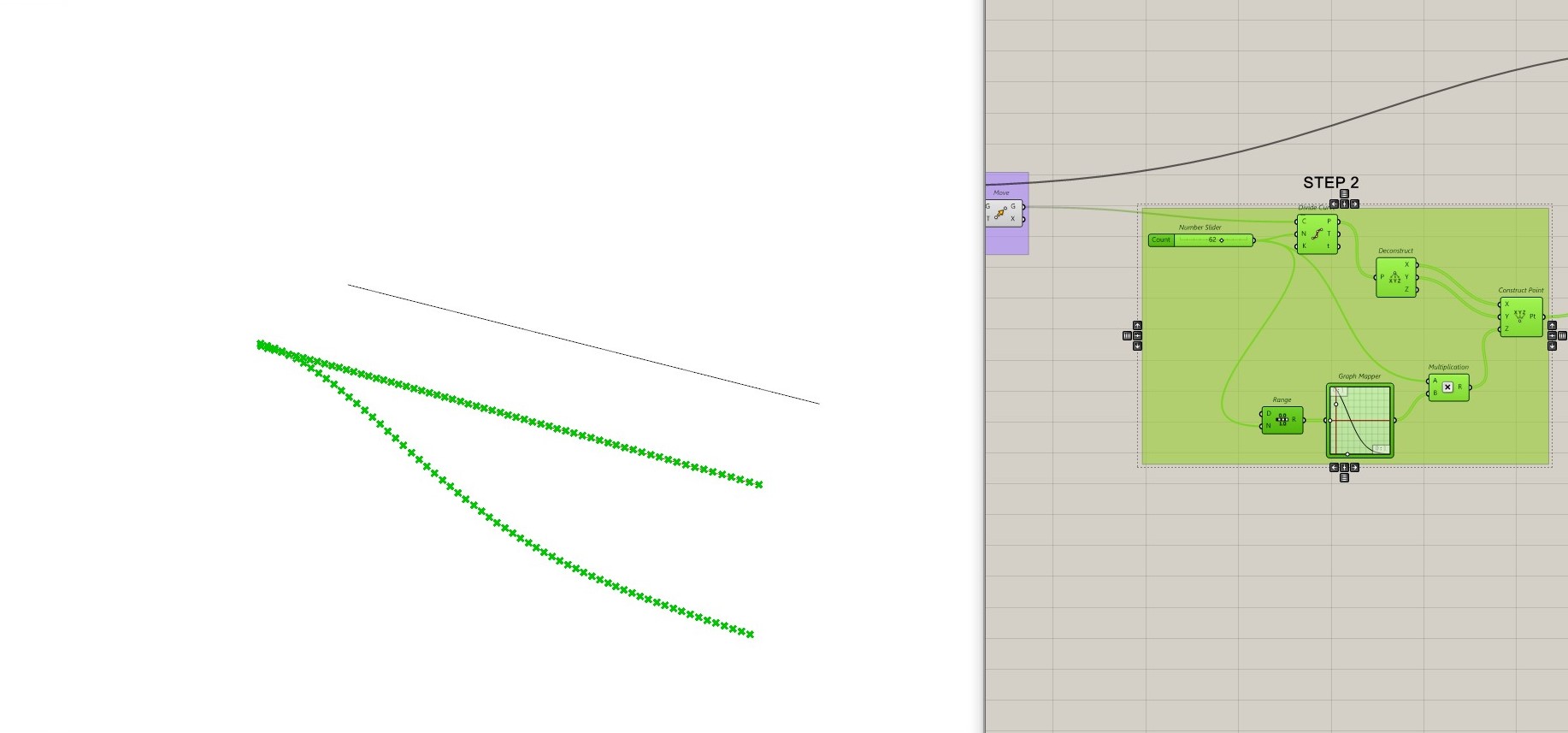
STEP 2
Use the “Divide Curve” component to divide your moved curve into points, the quantity is defined by number slider. Connect the moved curve to the “Curve” input.
Use the “Deconstruct” component to extract the individual segments of the curve. Connect the output of the “Divide Curve” component to this input.
Use the “Construct Point” component to create points from the deconstructed curve.
Use the “Range” component to generate a range of numbers based on the number of points. Connect the “Count” output of the “Divide Curve” component to the “Count” input of the “Range” component.
Use the “Graph Mapper” component to control the distribution of the steps. I have chosen the “Bezier” type to create this exact curve.
Use the “Multiplication” component to multiply the graph-mapped values with the height (Z-direction) of your steps. Connect the output of the “Graph Mapper” to the “B” input of the “Multiplication” component. Then, connect the output of the “Multiplication” component to the “Z” input of the “Construct Point” component. Afterwards join with number slider using with “Range” and “Divide Curve”.
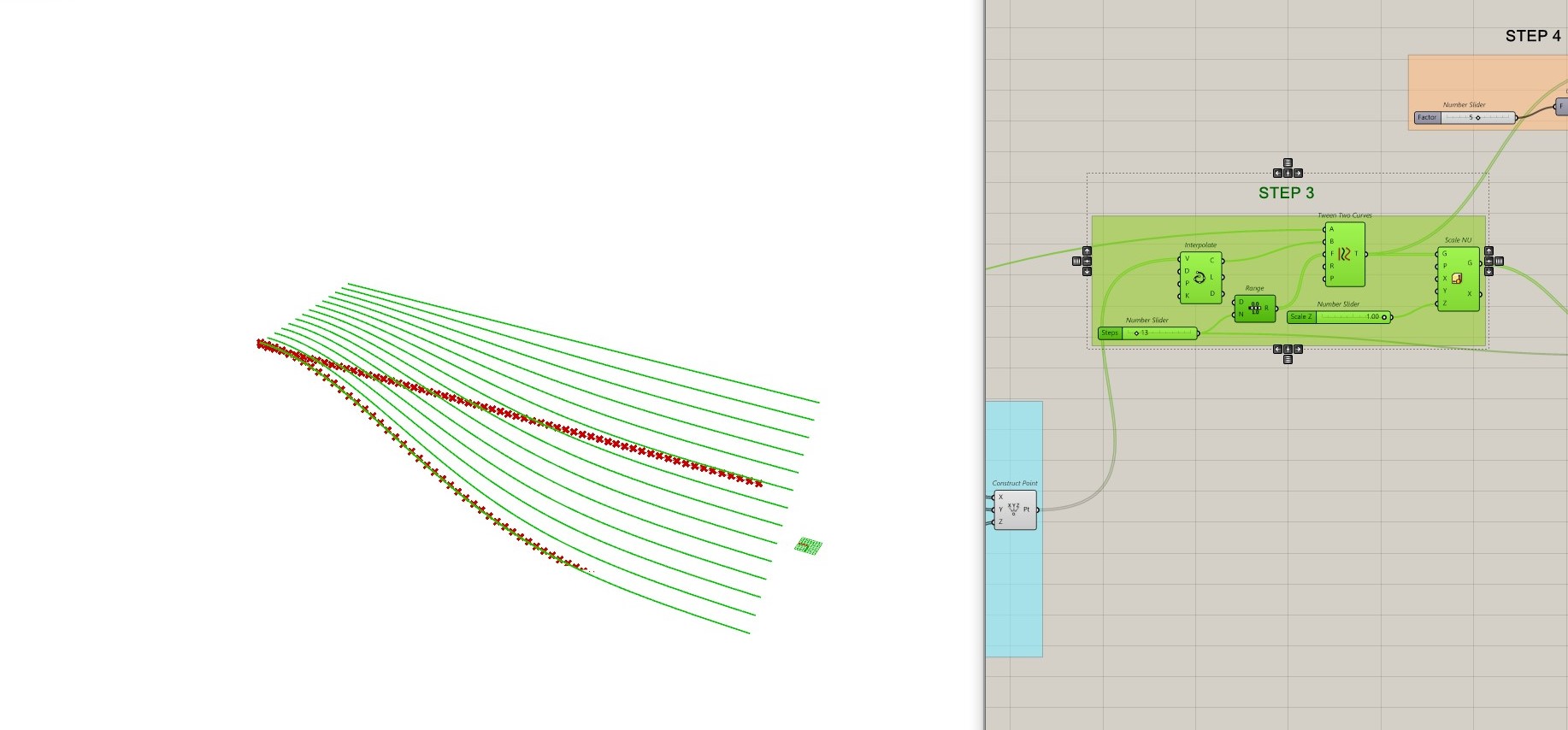
STEP 3
Use the “Tween Between Two Curves” component to generate intermediate curves between two specified curves. This operation creates a smooth transition between the curves.
Interpolate points along the generated curves. This step creates additional points between the control points, providing a smoother variation.
Generate another range of numbers based on the number of interpolated points.
The scaling factor adds depth to Z-direction of the staircase. This step scales the range of values, influencing the overall Z-scale of the interpolated points and, consequently, the curves.
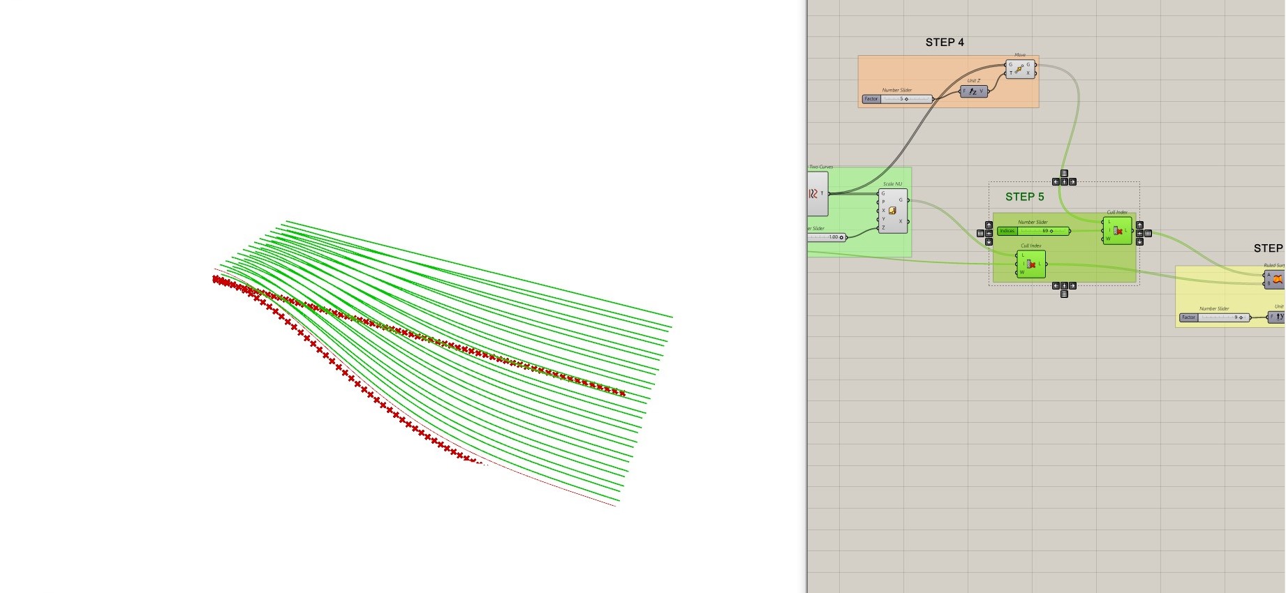
STEP 4
After that, add “Move” component to the “Tween Two curves” command moving it along the Z axis (enabled by “Unit Z” and “Number Slider”
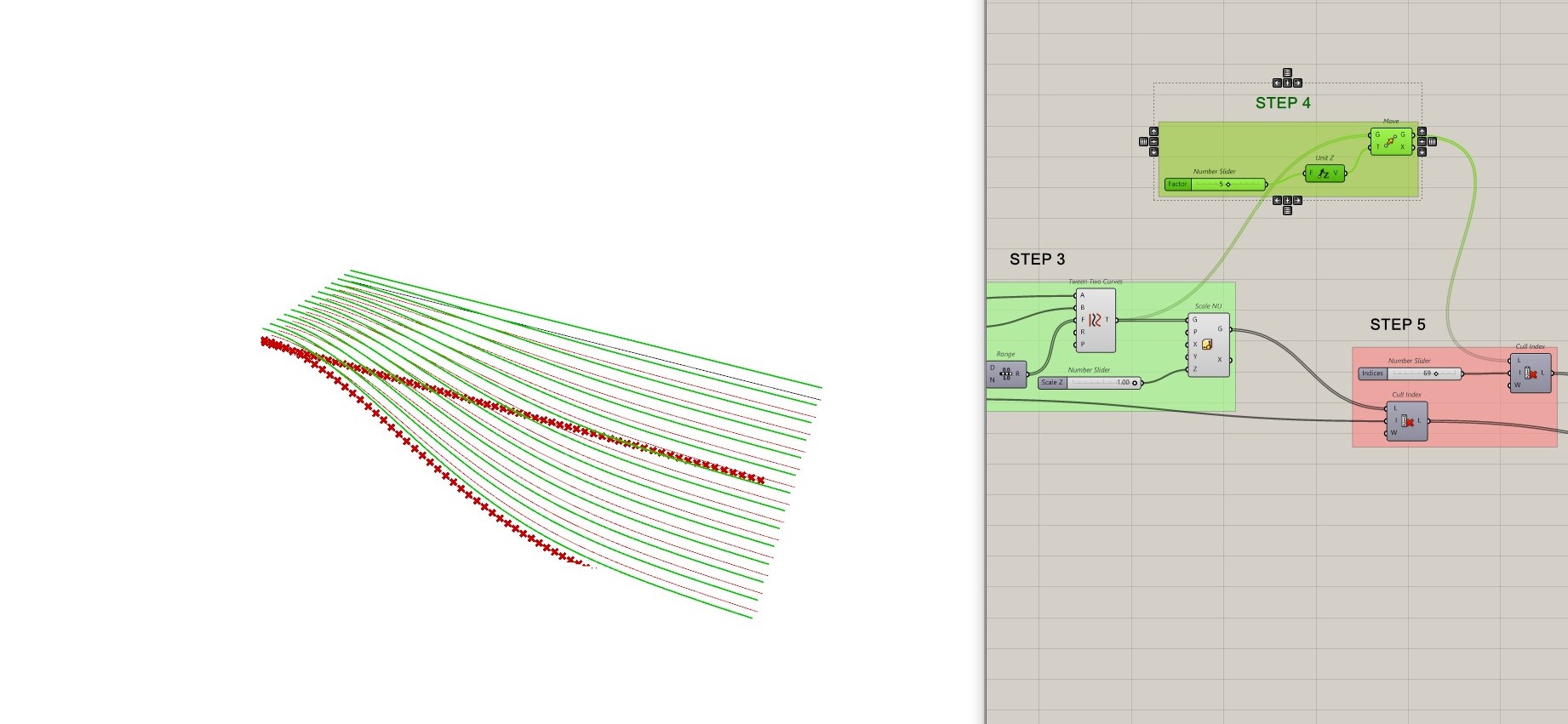
STEP 5
Use the “Cull Index” operation to selectively remove points from the scaled set of points. This step involves removing certain points based on their indices, helping control the density or arrangement of the points on the showing “Ruled Surface”.
Use another “Cull Index” after the second scaling operation. This step serves a different purpose than the previous culling, it removes certain points from the moving curves and reflects it to the surface.
STEP 6
Create a “Ruled Surface” using the moved points. This is a surface that passes through a series of profile curves or points.
Extrude the ruled surface to give it thickness using the Y-direction and specified “Number Slider”.
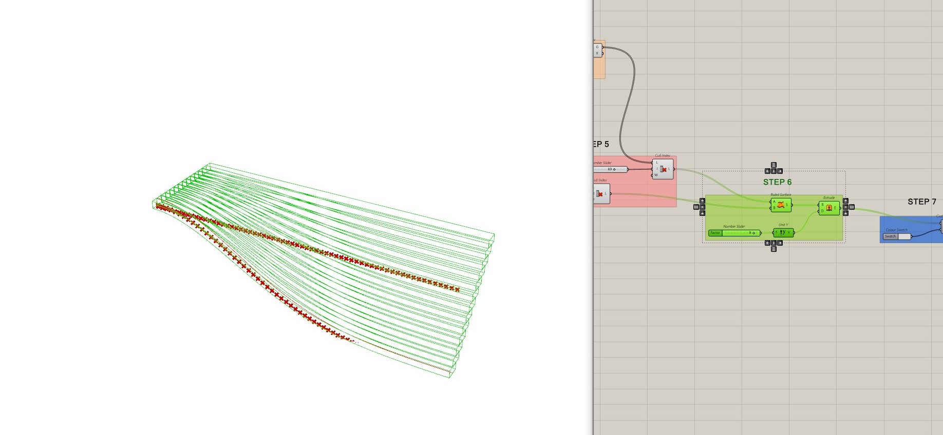
STEP 7
Use the “Custom Preview” component to apply a custom color to the geometry. Connect the command to the “Extrude” input and set the color using the “Colour Swatch” input, adding custom colour to the mass.
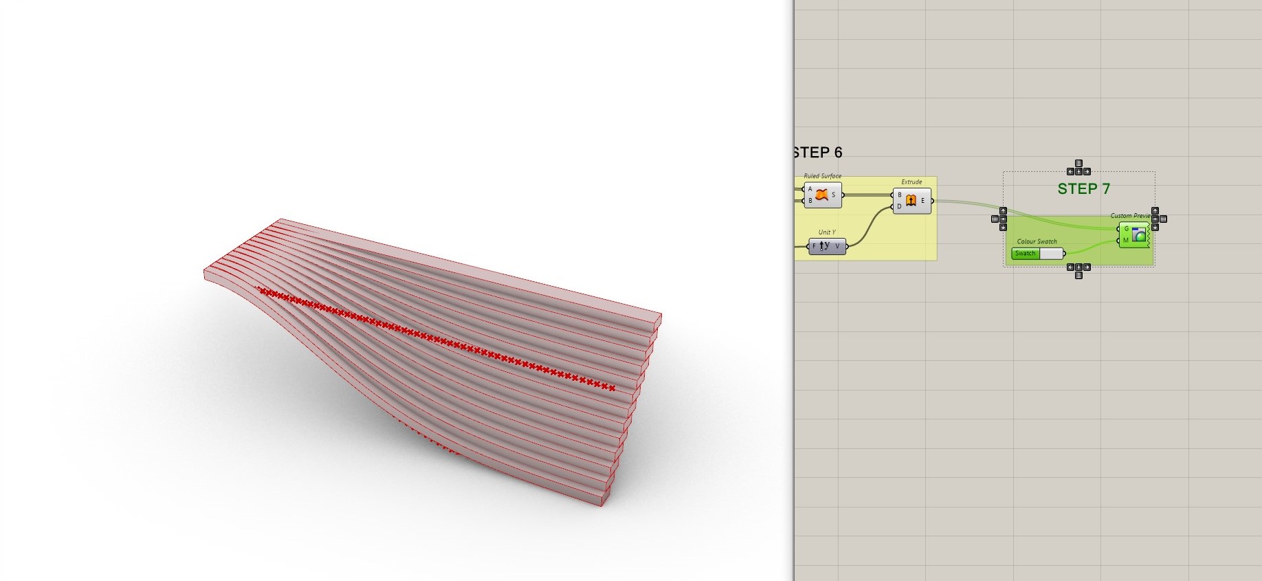
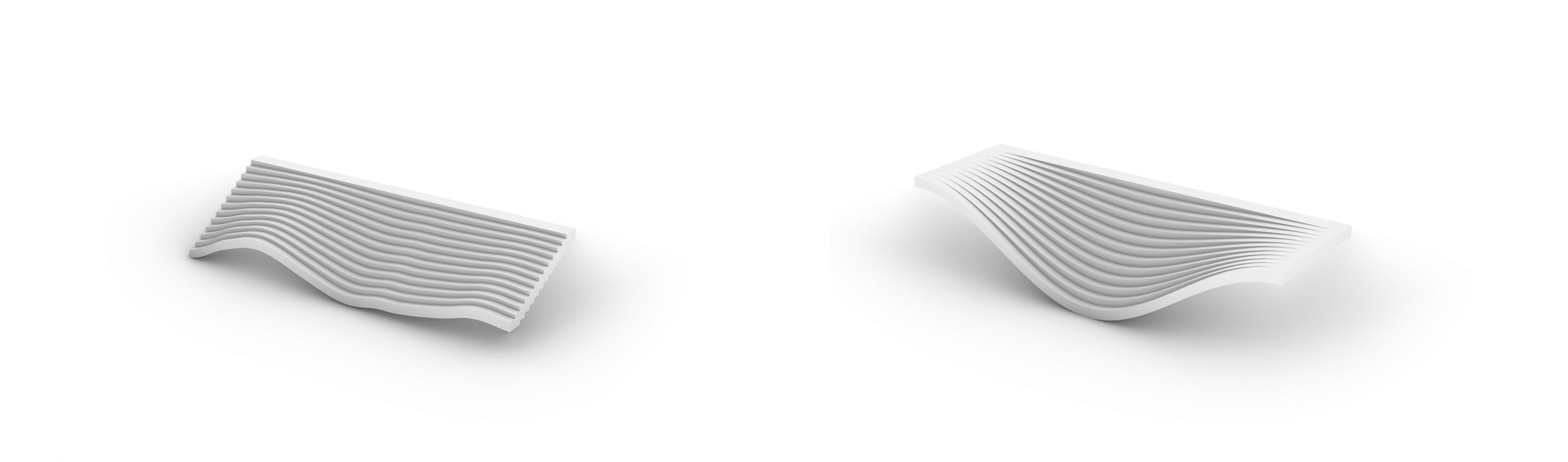
RESULT
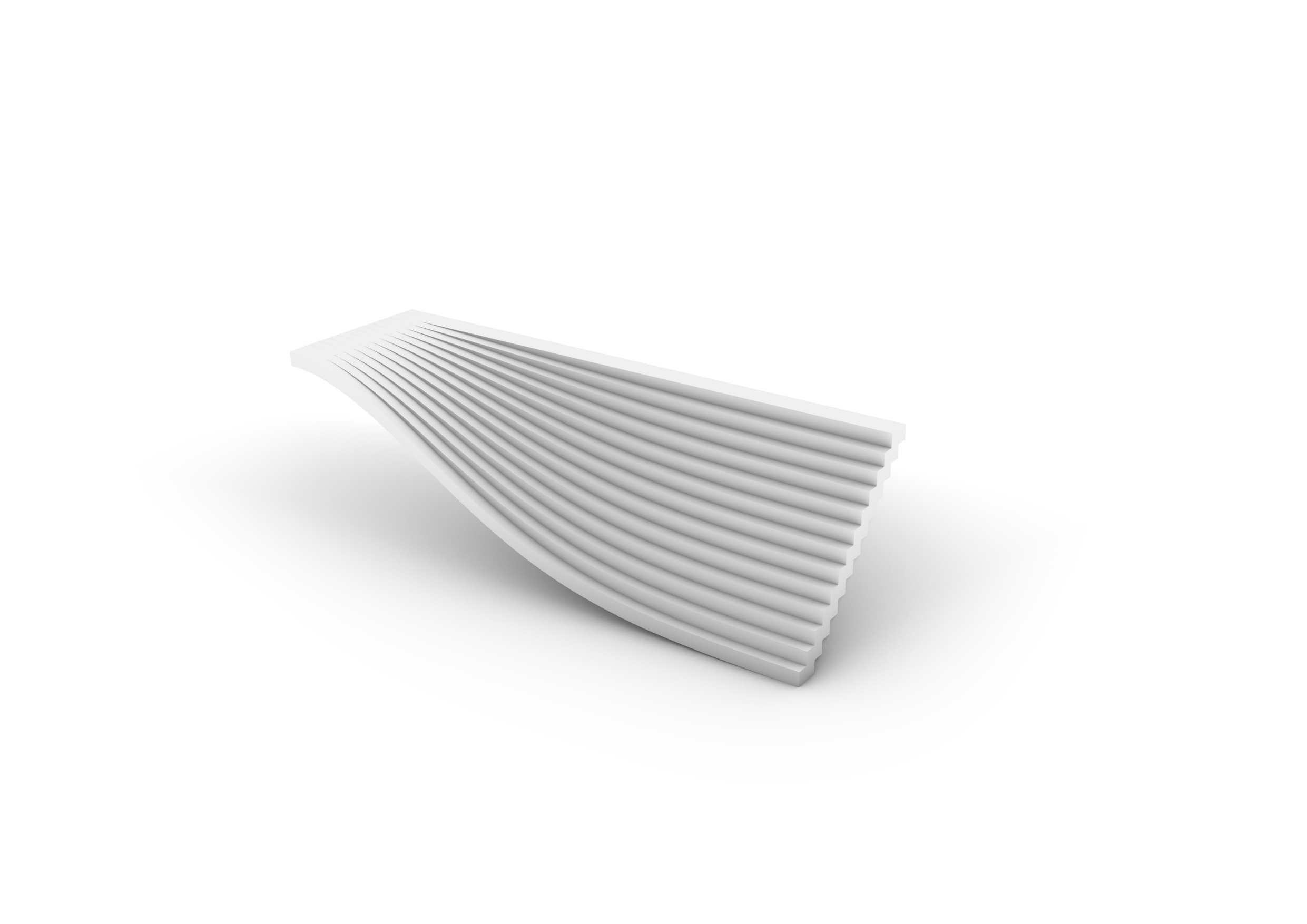
I also tried different shapes of staircases by changing “Graph Mapper” types, for example changing from “Bezier” to “Sine” and “Sinc” type.
INSERTION INTO THE ENVIRONMENT