Intro
In this tutorial you can find the steps to create a parametric shading facade.
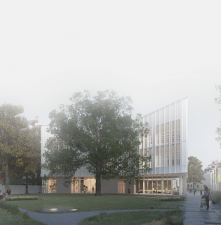
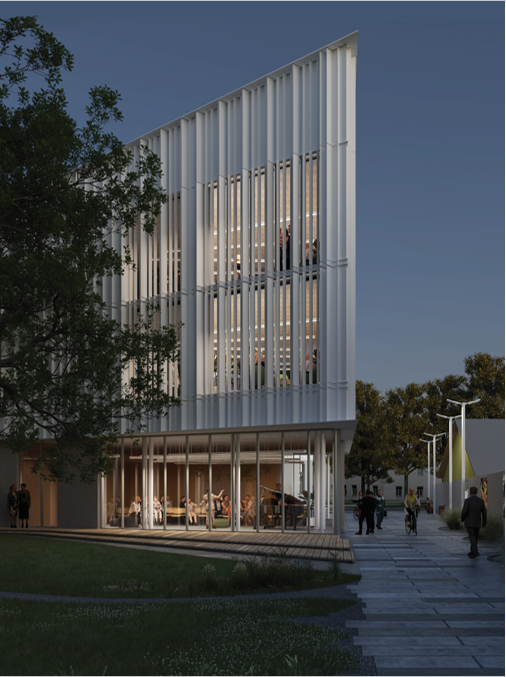
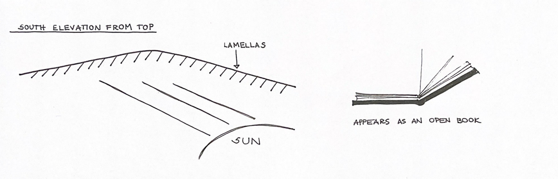
The facade was created for a library building project. Its purpose is to ensure maximum transparency and minimum overlight. The panels also serve as a tectonic facade element. The inspiration for such panels came in form of an open book, which ties in well with the library concept.
The aim:
To create a geometry of the facade elements that are parametrically optimized in relation to daylight conditions to reduce internal overheating.
Step-by-step tutorial
Step #1
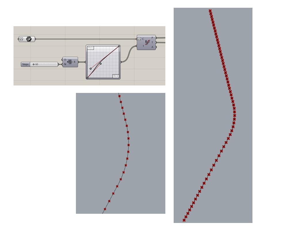
In Rhino place the selected polyline from Sketchup file, which is the contour of curved façade in floorplan. Sets the polyline as a Curve (Crv) ir Grasshopper.
The Evaluate Curve (Eval) component divides the polyline into several parts. With the Graph Mapper (Graph) component, it is possible to change the location and distance of these segments from each other.
Step #2
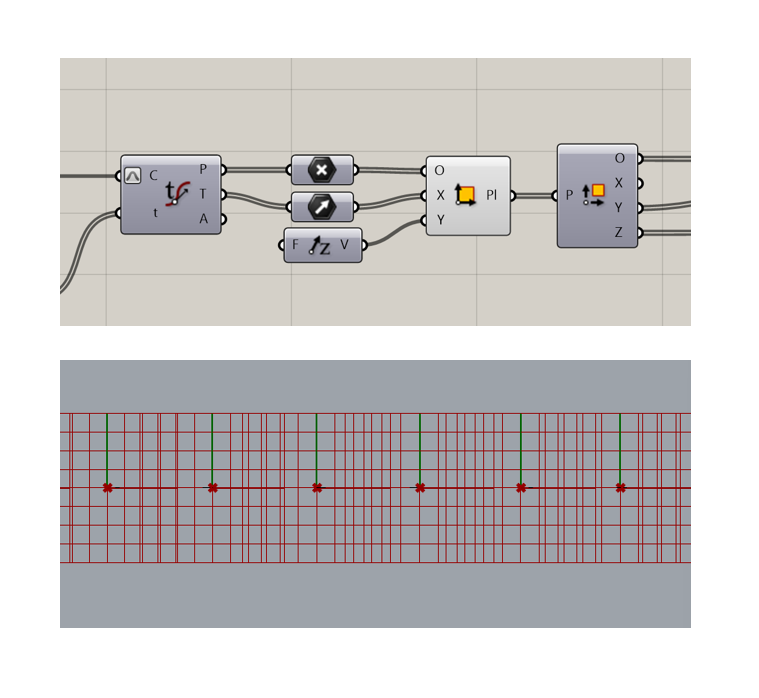
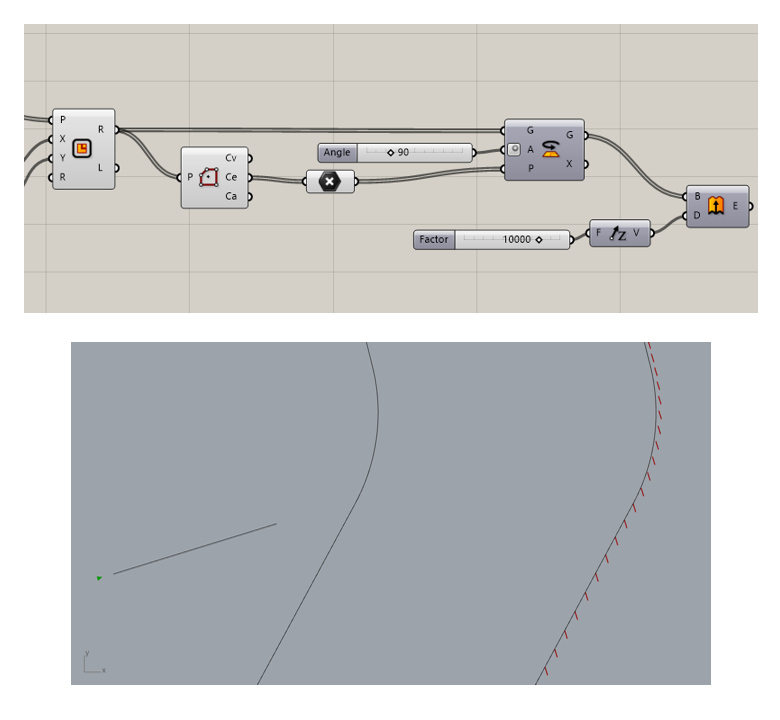
Planes in the yz coordinate plane are created through each of the resulting points. (The picture shows the planes in Right view)
The component Deconstruct plane (DePlane) is used. To obtain the coordinates of the planes that will be created in the xy coordinate plane. These planes will later be rotated according to the set solar ray vector.
Step #3
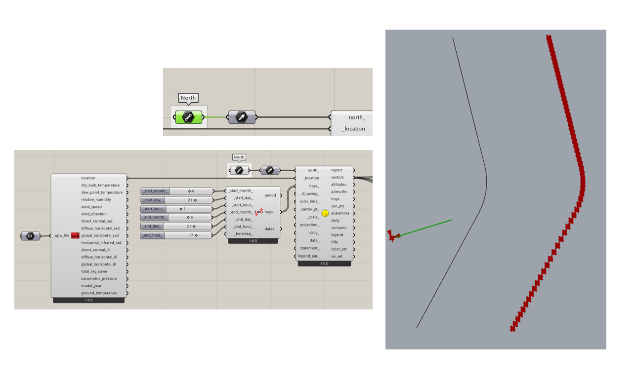
To make the rotation of the lamellas depend on the sun, the Ladybug plugin is needed. Prepare the selected .epw file, select the components LB Import EPW (ImportEPW), which is connected to LB SunPath (SunPath). As well as LB Analysis Period (AnalysisPeriod), where months, days and hours are set.
Then manually set the appropriate north direction as a line in Grasshopper and convert it to a vector. Sets a point on this line as the North reference point.
Step #4
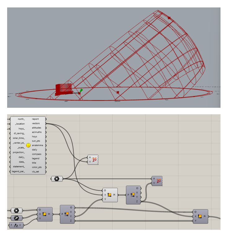
The y-axis of the created vertical plane is set perpendicular to the solar vector.
This plane is divided into components to obtain the z direction, which is perpendicular to the vector in the horizontal plane.
The obtained z direction is used as the horizontal plane on which the base of the lamellas is located in the x direction. The x axis will be parallel to the z coordinate of the vector plane.
Step #5
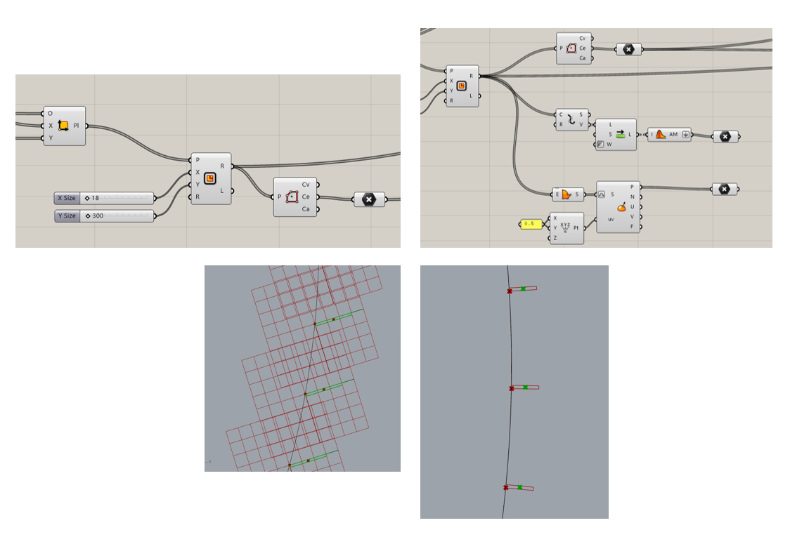
On the resulting plane, a rectangle is created with the appropriate dimensions for the base of the lamella. Since the panels are parallel to the sun vector, they need to be rotated 90 degrees.
In order for the rotation to be performed correctly, it is necessary to find the center of the rectangle, which can be done in three different ways. Choose one and find the center of the polygon.
Step #6
The polygon is rotated 90 degrees around the obtained center.
The routated polygons, the bases of the lamellas, are then extruded to the required height.
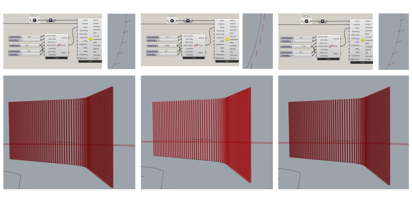
# Rotation of lamellas depending on the angle of the sun at specific times of the day, 7 in the morning, 1 in the afternoon and 5 in the evening
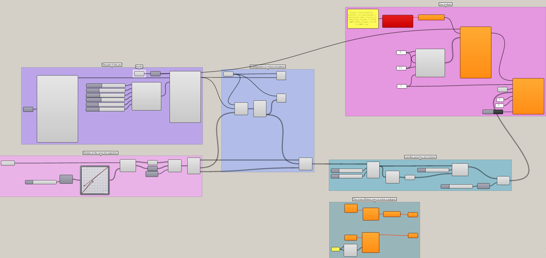
# Overview of the file
Result and feedback
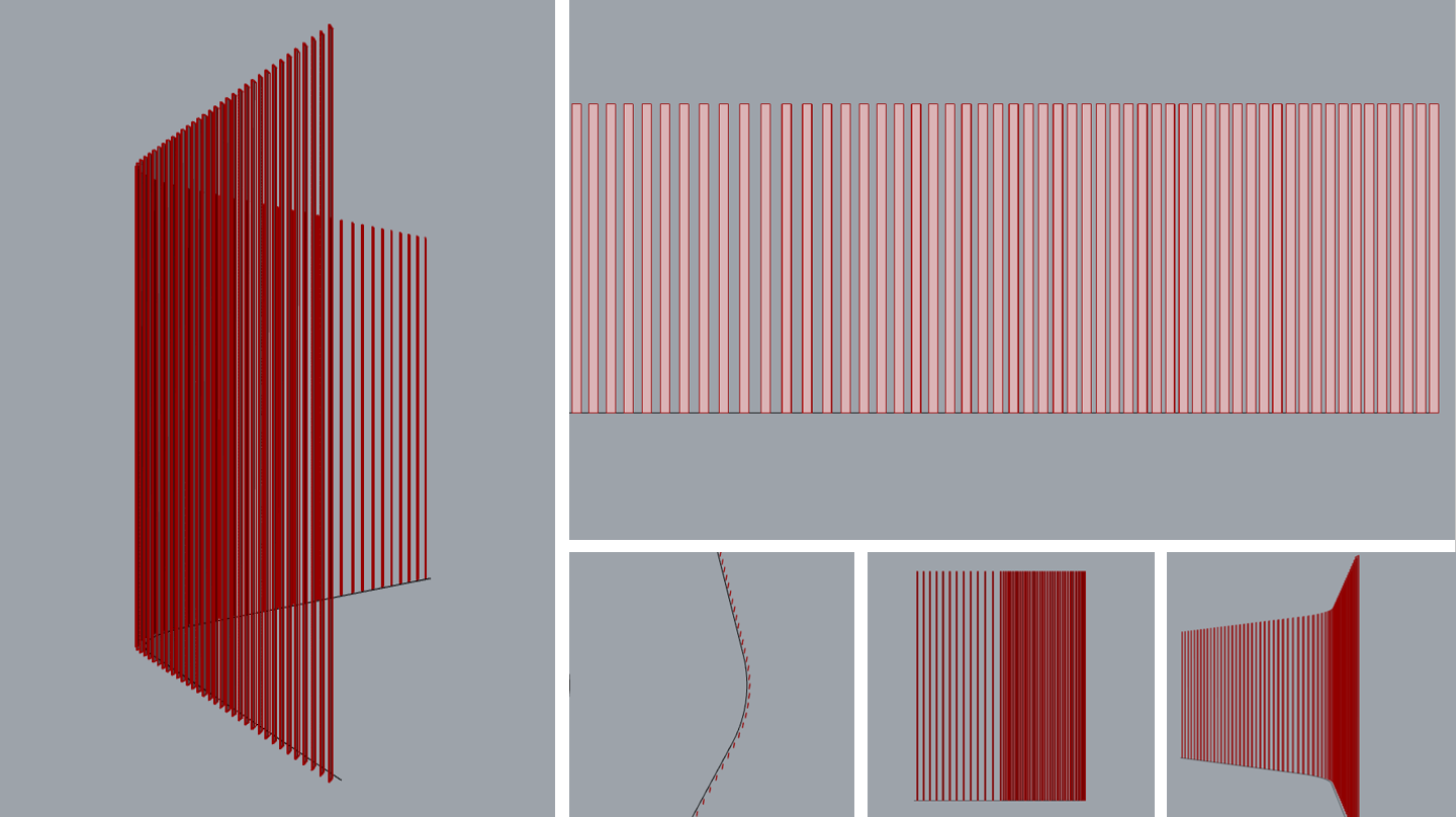
The resulting geometry can be further be baked and rendered as a 3D model by changing the color and other parameters. This code could be simplified by taking the 90 degree rotation out, instead connecting the vector and panel planes properly.
It is also possible to perform a daylight analysis for the created facade geometry using the Ladybug plugin. Analyzing, for example, how depending on the dimensions of the panels, their number on the facade or their mutual arrangement, the interior radiance changes.