The aim of this tutorial is to show step-by-step how to create, using Grasshopper, an arched path following a topographical surface.
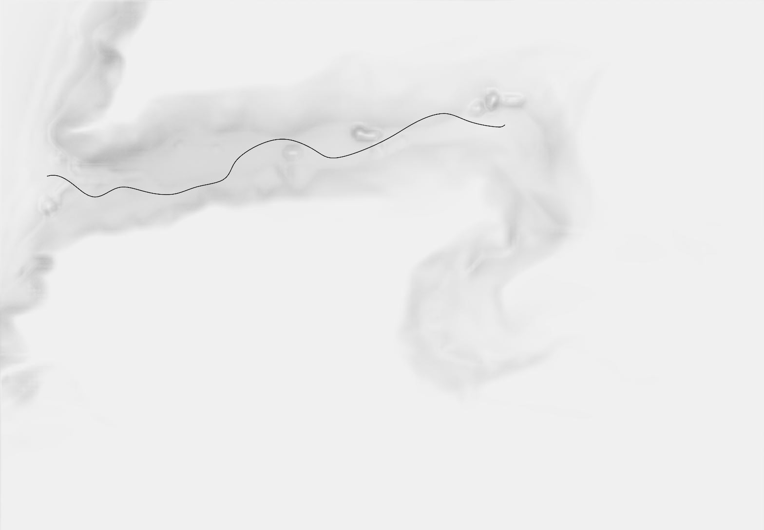
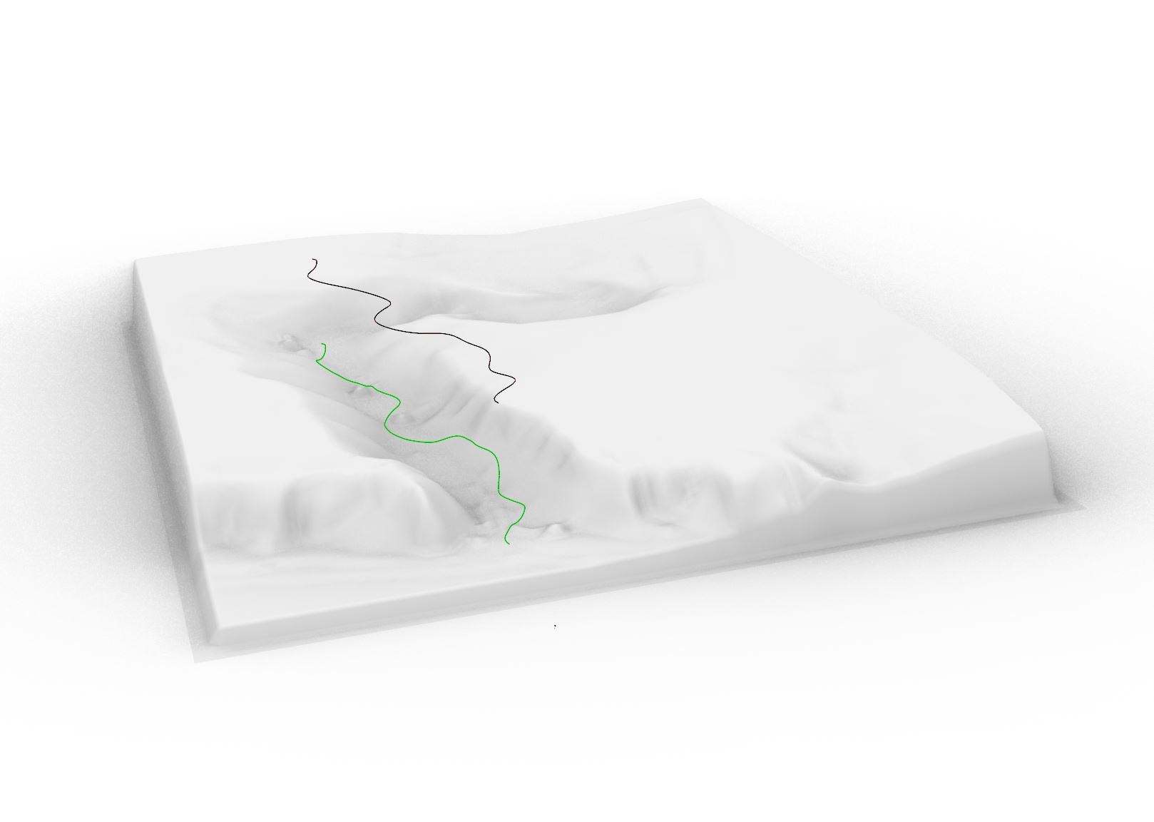
The first step is to draw a curve tracing the desired course in the XY plane, above the topographical surface (see : Image 1). In Grasshopper, it is advised to “internalize data” for the curve and surface used (right-clic on each component).
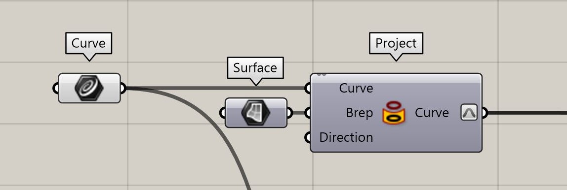
Once this is done, the “project” command gives the 2D curve the same relief as the topography below (see : Image 2). At this point, the curve should be reparameterized to start at “0” and end at “1” as to simplify the upcoming steps (right-clic on the “curve” output).
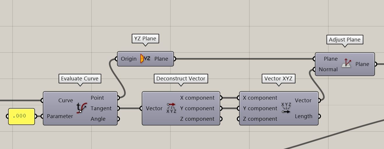
To ensure the path is adequately built it is necessary to do some orientation gymnastics. The “evaluate curve” command set at “parameter” 0.000 gives us the tangent at the start of the path’s course. The X and Y component of this vector can be used to create a new 2D vector (the Z component is ignored to avoid the tilting of the path) to be used as “normal” in a plane as to be oriented on the curve.
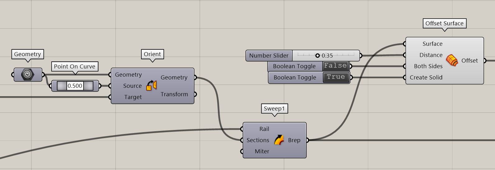
To create the path, set a line in a “geometry” component with the desired width of the path. Before sweeping this line along the path’s curve, the “orient” command should be used to place the line correctly on the curve. : the “source” should be the point 0.500 of the line and the “target” is the “plane” output of the previous step.
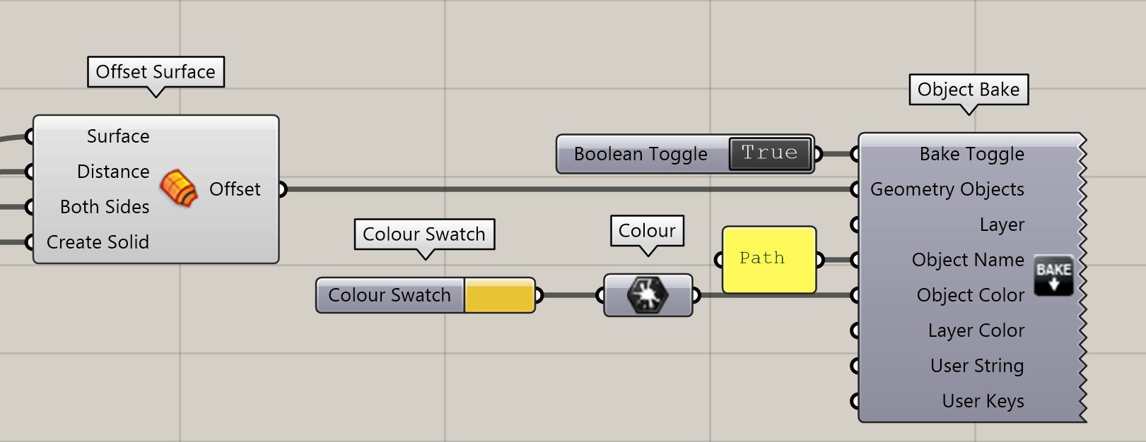
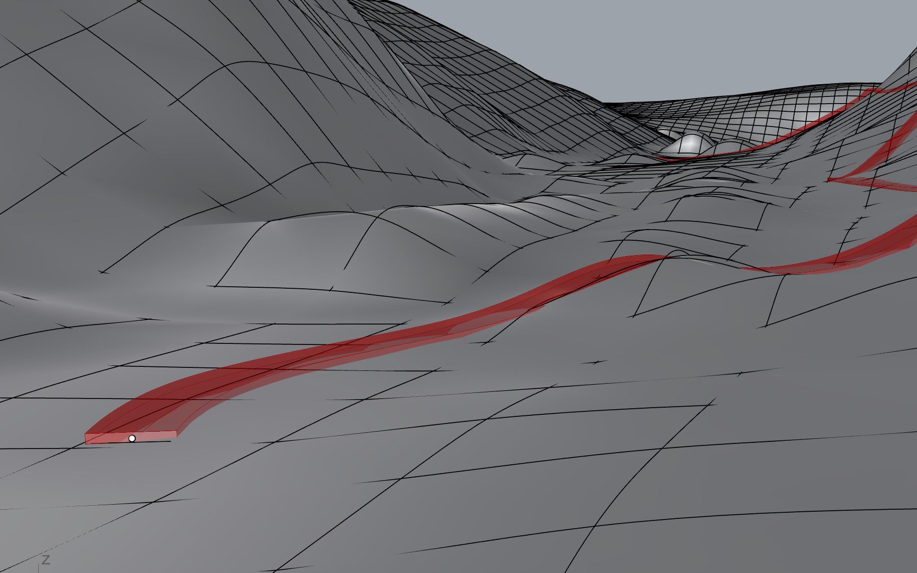
Once the projected curve is set as the “rail” imput in the “sweep1” command, the resulting Brep should be used as a base surface from which to offset the thickness of the pavement, using the “offset surface” command (see : Image 3).
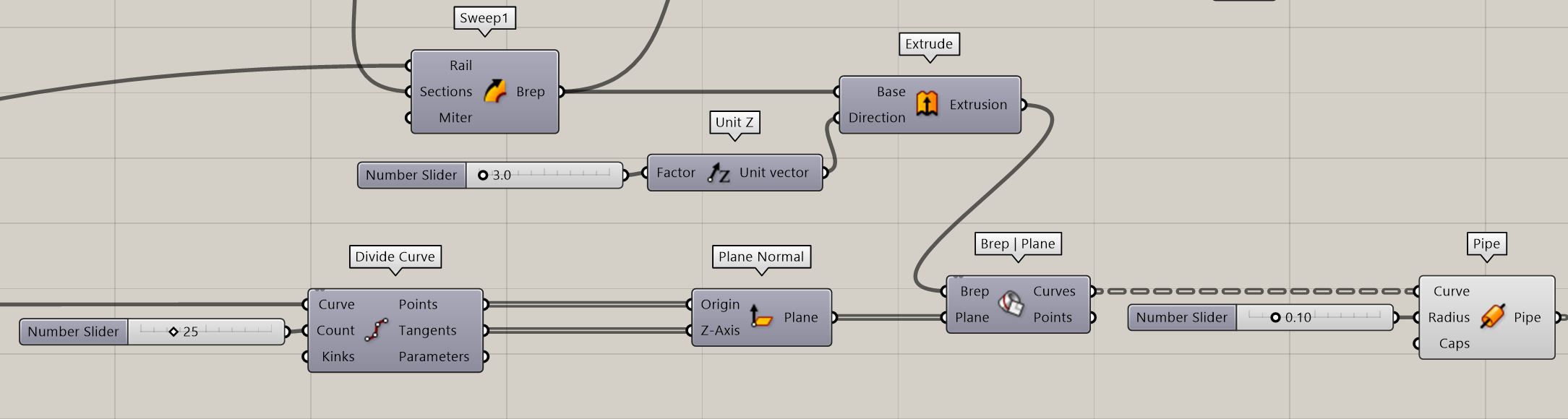
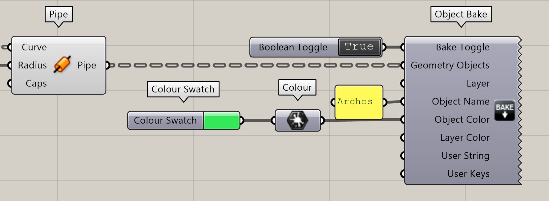
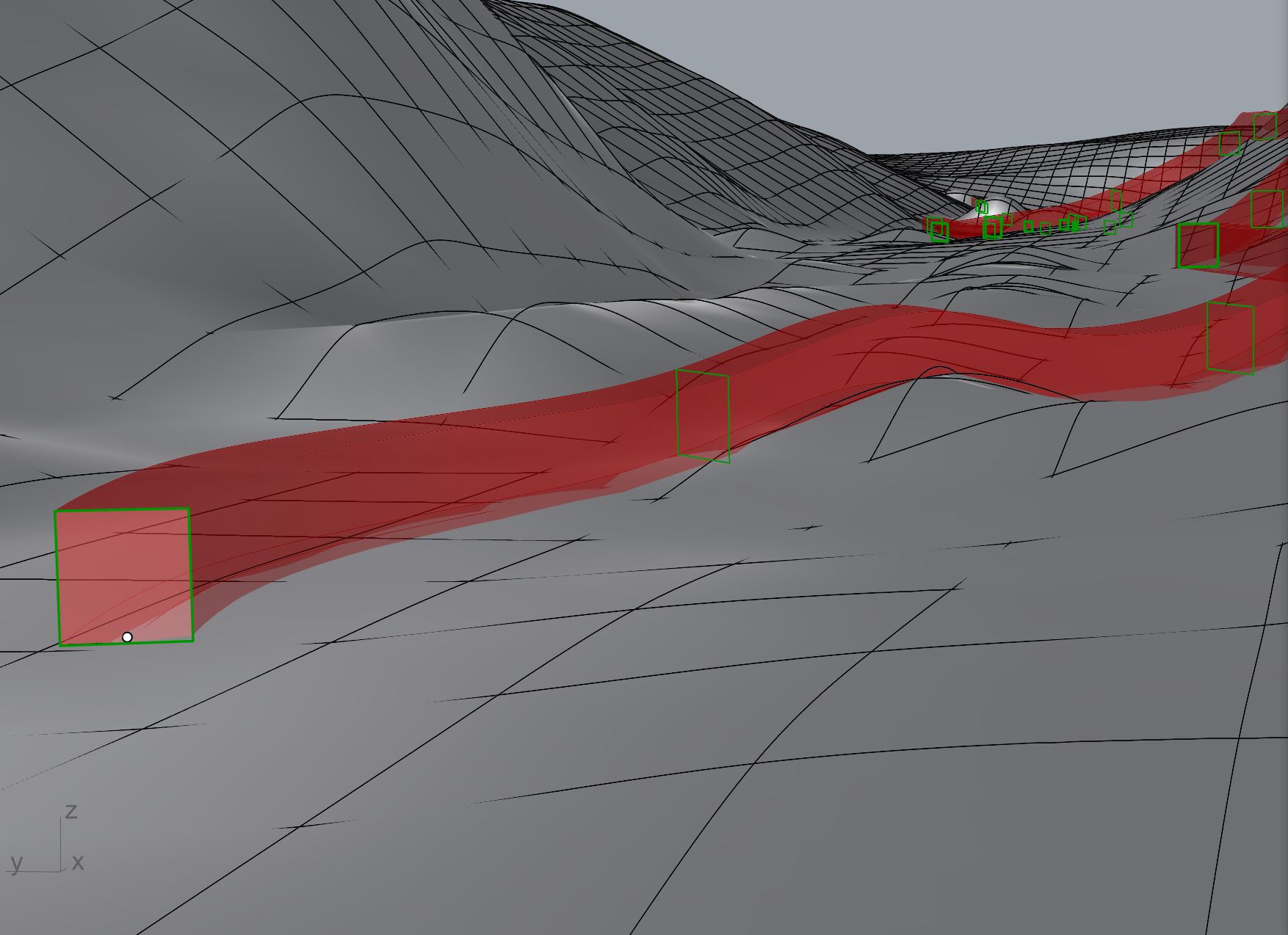
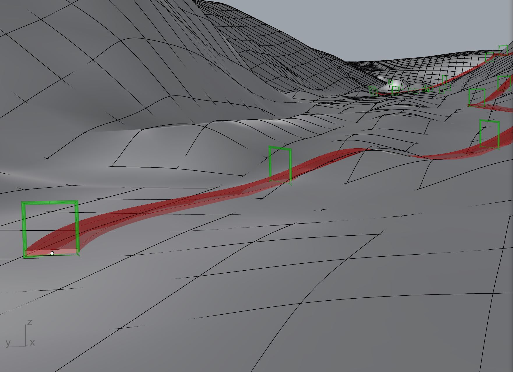
The resulting Brep will also be used as a “base” for an upward extrusion. Using the “divide curve” command on the initial projected curve will allow for the creation of multiple (the number can be set in the “count” imput) perpendicular planes along the curve. These planes will be used to intersect with the extrusion, using the “brep | plane” command (see : Image 4). The resulting curves will then be thickened by the “pipe” command as to create the arches (see : Image 5).
The path and arches can then simply be baked, with the desired parameters :