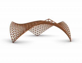
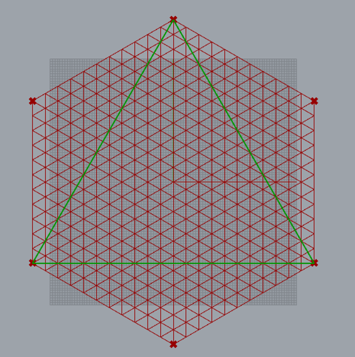
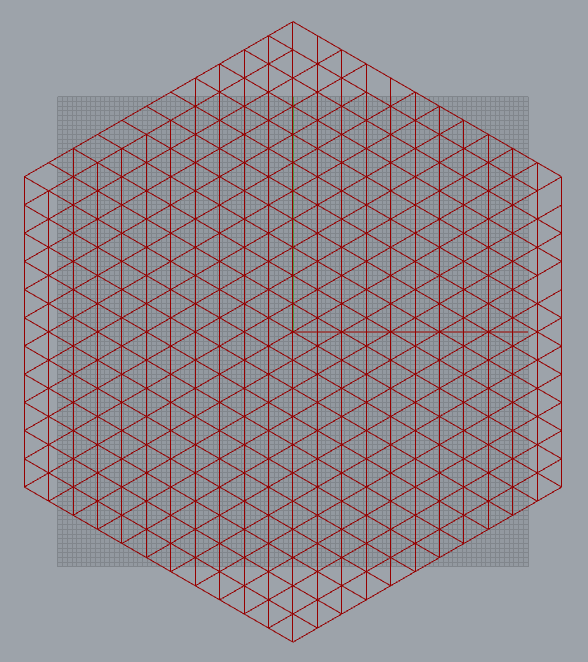
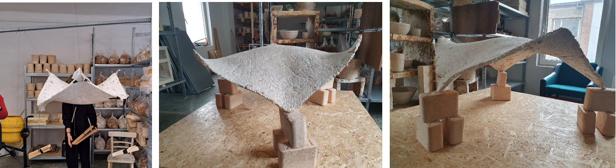
This tutorial shows the shape and structure to my projected mycelium house roof. My intention was to create a pattern that could be easily built and simulate this building process of creating a planar grid and lifting it by pulling and anchoring some of external points while adding a pulling in the middle and three corners of the structure As the shape of roof is hexagon, I used triangular grid, where each lines direction is parallel one of the sides, making structure more stable. In real life structure would be made of timber as a gridshell structure but mycelium part would be made by hanging and adding some forces.
For this Script you will need the Kangaroo plugin.
Modelling process
Constructing the grid
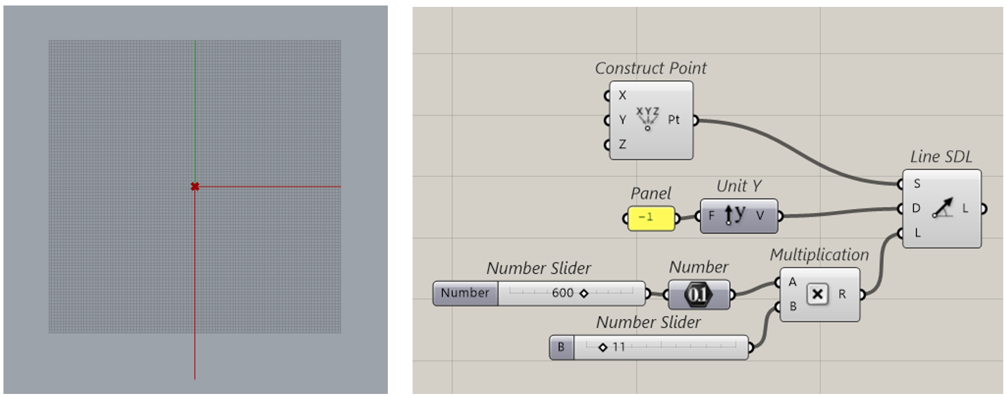
Step 1
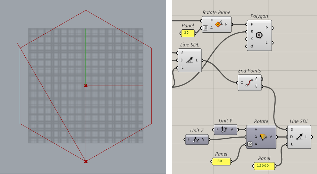
Draw one SDL line from center to the outer corner. Use “multiplication” to set the distance, that will be between parallel gridlines and number of segments. The result of multiplication will be the length of line that will be the same length as hexagon edge.
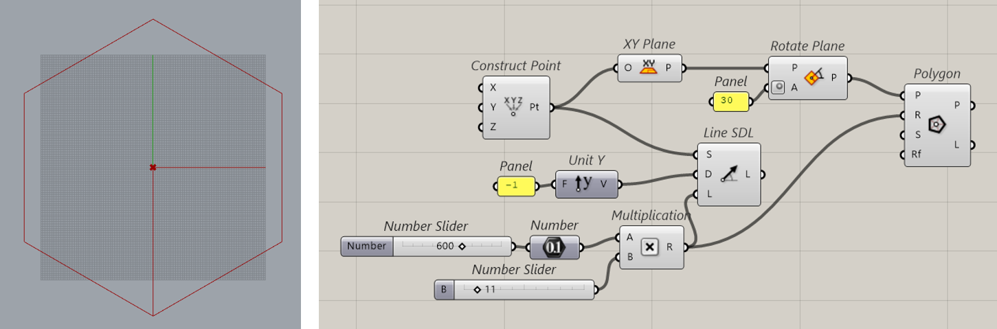
Step 2
Using this SDL line construct the hexagon.
Step 3
Rotate the SDL line that it becomes perpendicular to two parallel edges.
Step 4
Explode the polygon and by using “List Item” we choose the directions of polygon lines and divide them into smaller equal length segments.

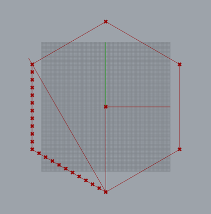
Step 5
Use shift list and invert wrap values to avoid duplicating corner point. Merge the values and flatten them.

Step 6
Find the closest point on previously rotated SDL line from each point by using “Curve Closest Point”.

Step 7
Draw multiple SDL lines by choosing the direction and setting length. To get the right lengths we take distances from using “Curve Closest Point” and multiply by 2. After that sum this multiplication output with previous multiplication output and the result set as SDL lines length.

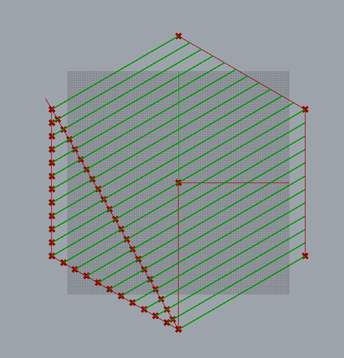
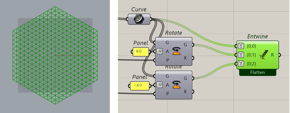
Step 8
To get the other two directions, we just rotate these ones. As rotation plane we set xy plane. To make grasshopper script simpler and combine data, we use entwine, which flattens all data streams. After that we simplify them as well.
Kangaroo simulation
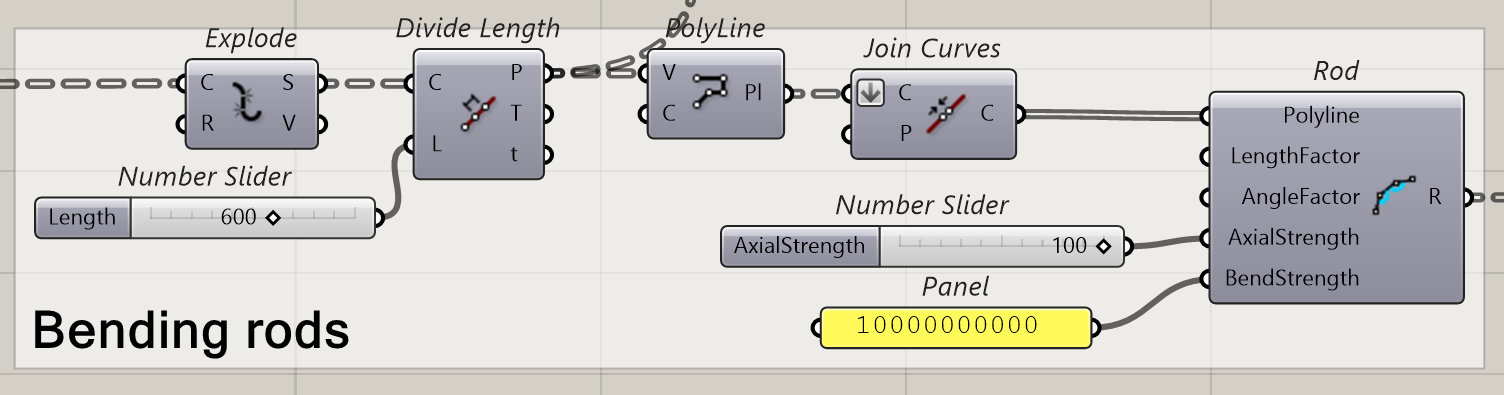
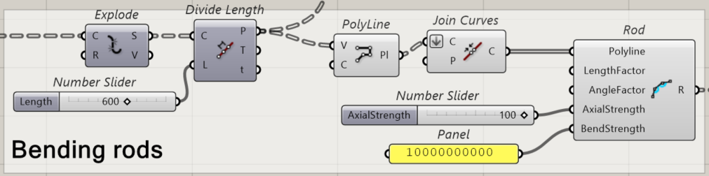
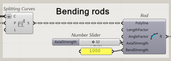
Step 1 – Bending rods
The main characteristic of gridshells is how they work in bent forces. To reach a similar physical approach we apply bending strength to the segmented polylines that create the grid. The axial strenght means that each polyline can bend in 100 points, that has a lot of forcing there.
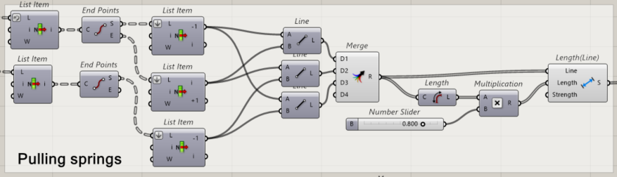
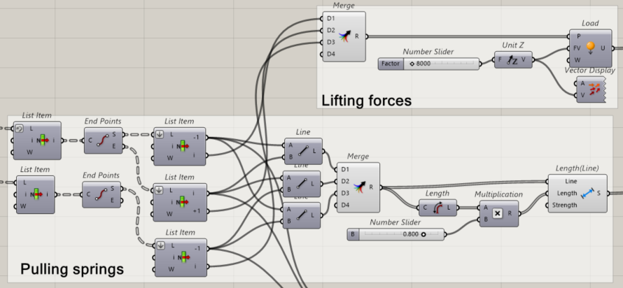
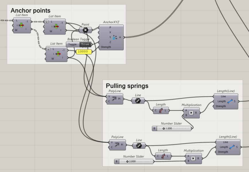
Step 2 – Pulling springs
In order to lift our structure, some of external points are joined together, this simulates the actual building process of a gridshell.
At first by using list item we select all corner points, then we make lines between every second corner, so the lines make triangle. After that we make them as Length (Line). The multiplication factor here should be less than 1 to work properly.
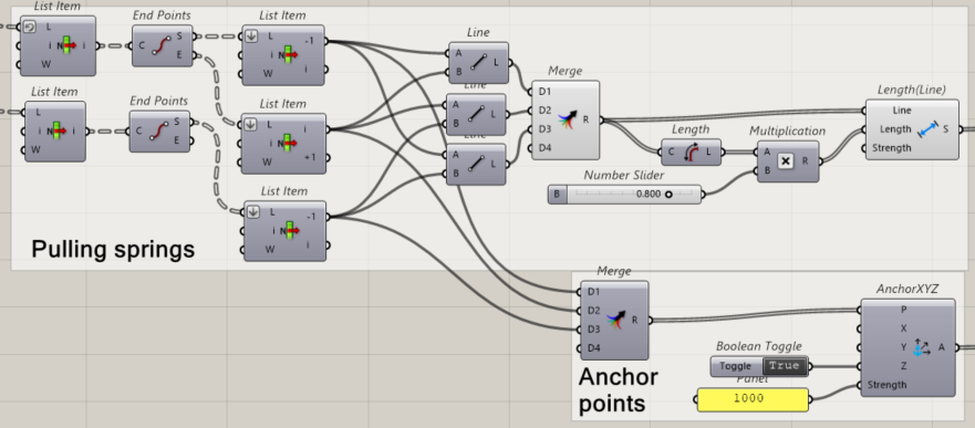
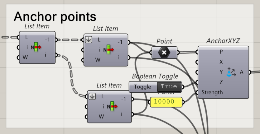
Step 3 – Anchor points
To connect our structure with the ground we establish some of extreme points as anchor points. The anchoring strenght can’t be too small, otherwise our structure will not stand on the ground.
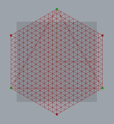
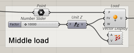
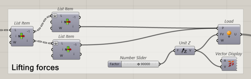
Step 4 – Lifting forces
In order to lift the structure, we add identical forces to 3 corners that are not anchored and larger force to middle point, to make the middle point the same height as corners.
Step 5
To later have surface we deconstruct mesh
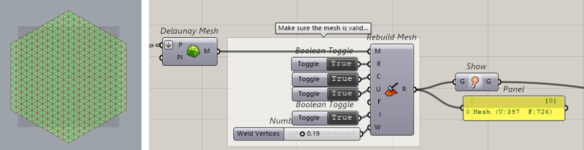
Step 6
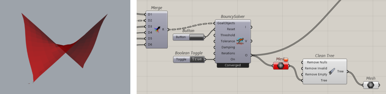
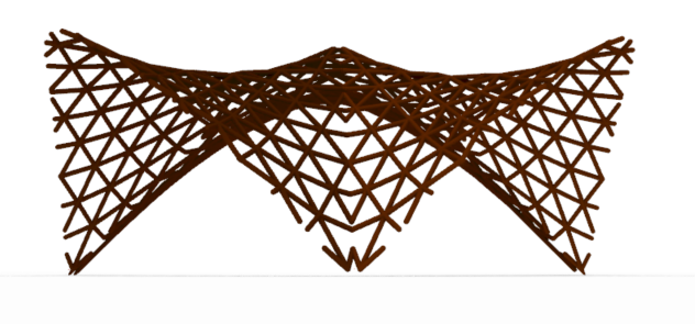
After we have made all necessary components, we work with kangaroo2´s component Bouncy solver, to reach a stable structure with some parameters given. Once we have our stable gridshell we can now clean the pulling lines.
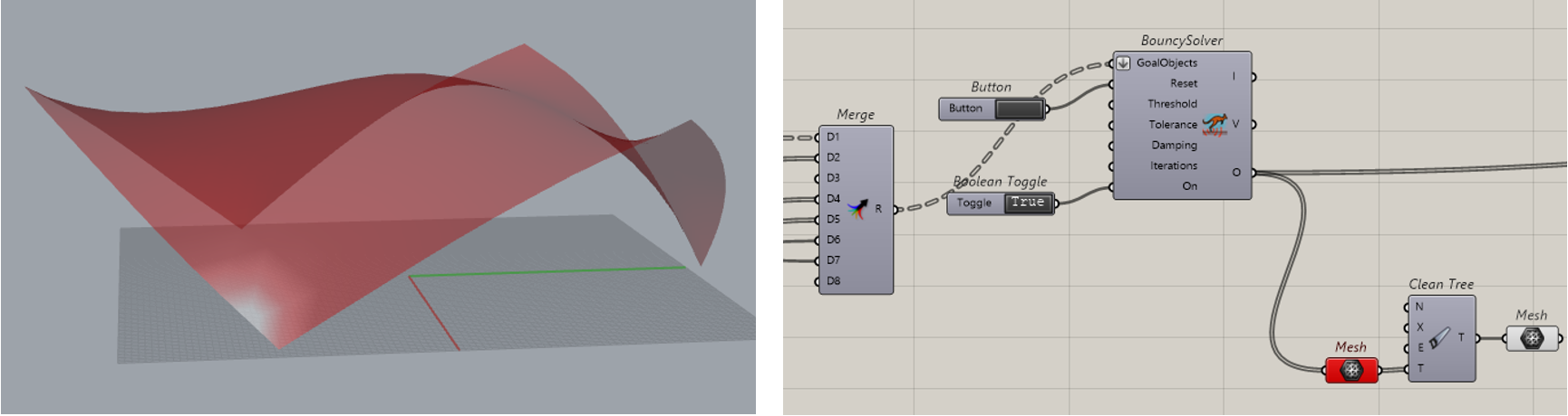
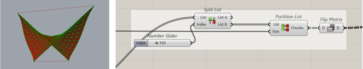
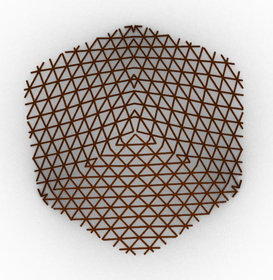
Result
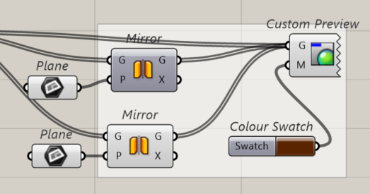
If we want to see the structure, we use split list and pipe elements, and the give them the color.
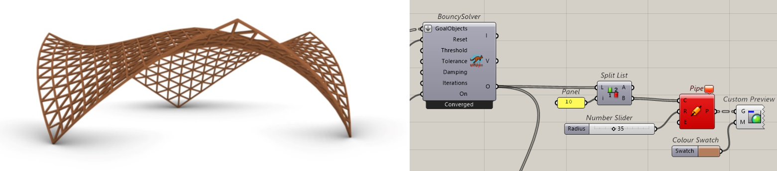
The issue started already here with polylines, we can see that some of them are missing, If anybody knows how to solve it, feel free to comment.
Different way to costruct grid
Step 1
Construct points in one line and set the length and direction for lines, that starts from those points. Repeat the same for 2 other directions.


Step 2
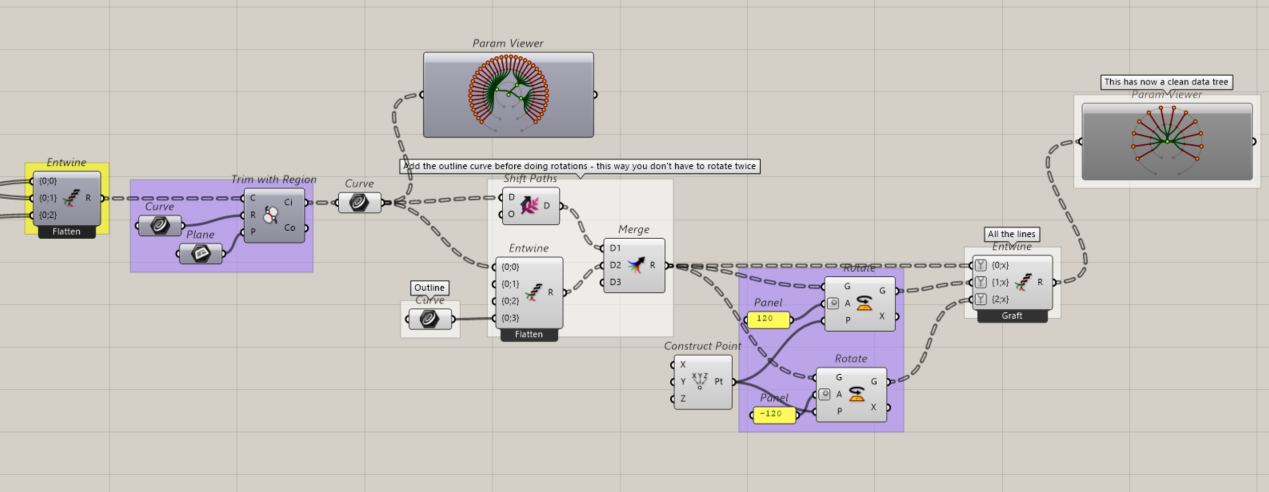
At first entwine all three direction lines, then draw a line in rhino, set as curve and trim those lines with region, after that you merge outline with grid, rotate it and entwine all data streams again. Now you have got the same hexagon with triangular grid.

This approach was not succsessful for me, but If you want to use something like this or see different way to get pulling springs and lifting forces, you can take a look on this file

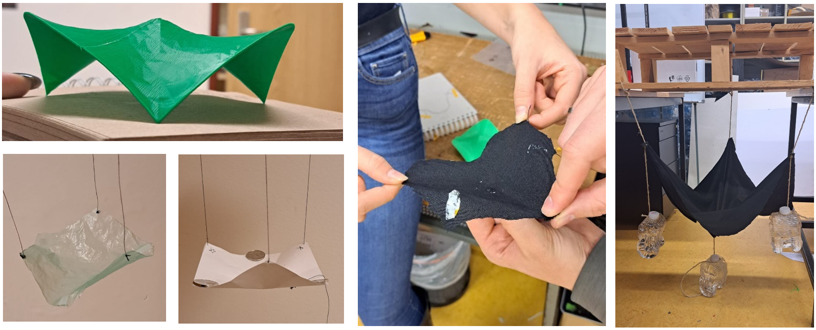
Little background of how I ended up to this solution
At first I wanted to make this structure out of three separate parts, the process of how I did it is below, but after a while I faced several problems, which about I will tell later.
Step 1
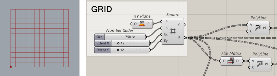
Firstly I created a squared grid by a simple component. And then out of those points got long polylines in two directions.
Step 2
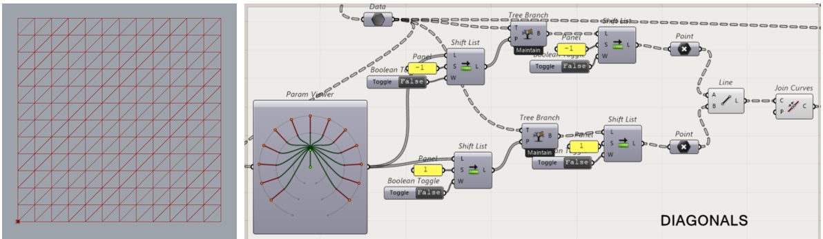
Then, by working on the list of points, I made the diagonal lines to make a triangular grid.
Step 3
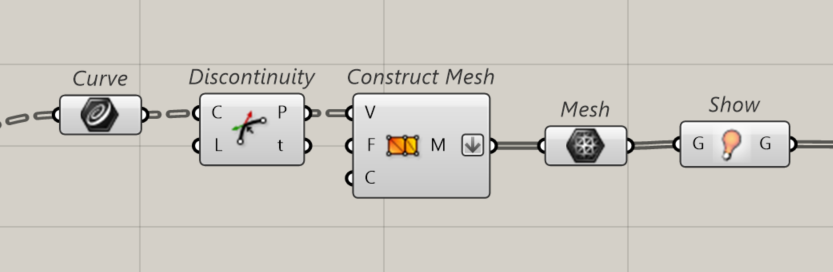
By using this I filtered the results for mesh and used that as cleaner output.
Kangaroo simulation
Step 1 – Bending rods
For this step I used Splitting curves component from donkey plugin, adding all three direction polylines to curves input and all crossing points to points input, and then to reach a similar physical approach I applied bending strength to the segmented polylines that create the grid.
Step 2 – Lifting forces
In order to lift the structure, I added identical forces to 2 opposite corners, which I found by using list item.
Step 3 – Anchor points
To connect our structure with the ground we establish 2 other corner points as anchor points.
Step 4 – Pulling springs
In order to lift our structure, some of external points are joined together, this simulates the actual building process of a gridshell. To get the right shape I needed to add bigger multiplication factors than 1, but in reality this wouldn’t work.
Step 5
Then I worked with kangaroo2´s component Bouncy solver, to reach a stable structure with some parameters given. Once I got stable gridshell I clean edthe pulling lines.
Step 6
By working with data tree I tried to get free of lines that connects the corners, because we don’t need beams there.
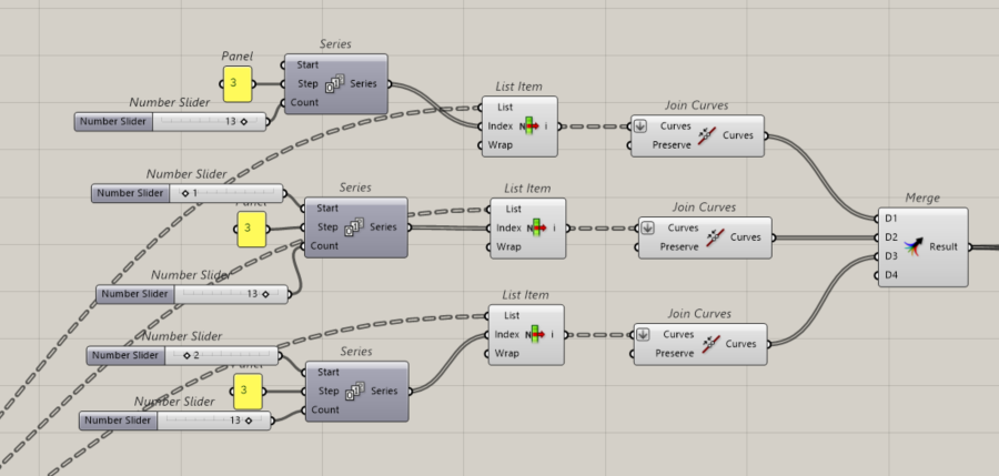
Step 7
In previous step I got all small lines, but now I need long polylines so I selected all three direction grid lines and joined curves.
Step 8
After I trimed those line with simple brep drawn in rhino and then constructed mesh pipes around the lines.
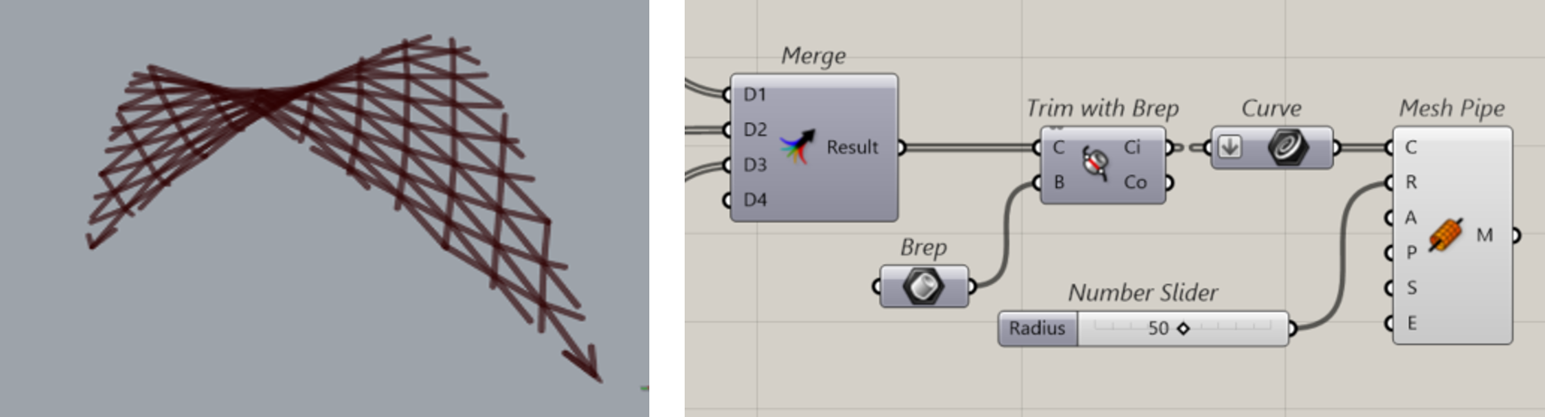
Step 9
Lastly mirrored this shape 2 times, and gave them color.
The issue here was that I couldn’t get the outline and connection beams, and after a while I also realised that this kind of grid doesn’t make sense and it is harder to manufacture it.
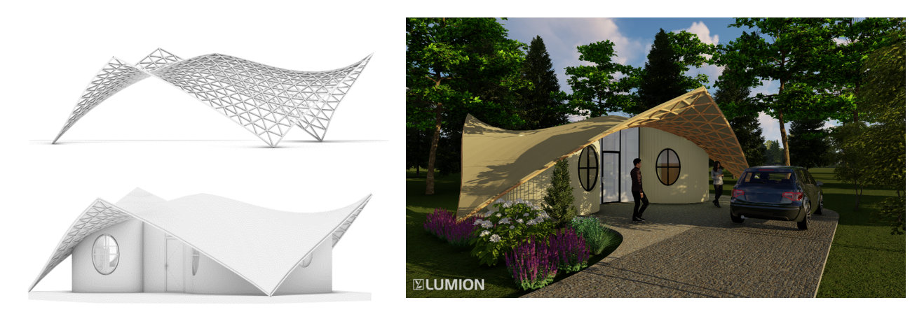
Application in architecture
Files
To download 3dm files, please click on the right side after the text.