Introduction
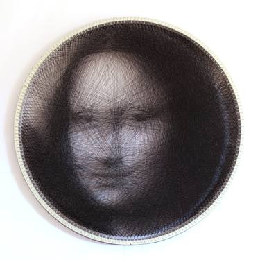
For this project, I wanted to explore how a parametric script could automate a traditional craft and artistic technique. String art relies on a simple principle, connecting pins with thread to approximate an image, but determining the optimal sequence of connections manually would be extremely time-consuming. Using Grasshopper allowed me to automate this process and apply it to a portrait or any image.
Translation into Grasshopper
- Geometric base
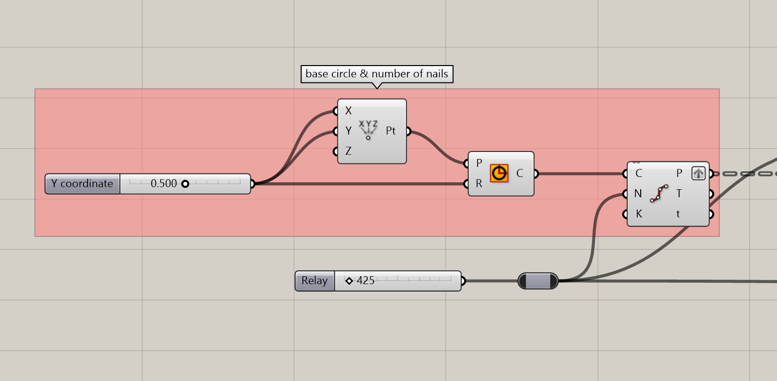
This is the beginning of the script, it sets the base circle and main features where the thread art will be generated.
The Number Slider (here set to 0.500) sets the X coordinate of a point constructed via construct point which defines the centre of the circle, and the radius R of the circle component.
The circle is then passed into Divide Curve where it is divided into a number of points. The number of division points is set by Relay (here 425, meaning 425 equidistant points are generated along the circle’s perimeter. These points represent the nail positions that will serve as anchors for the string art threads in subsequent steps. Note that these values can be adjusted depending on the image and/or the desired result.
2. Starting point & first lines
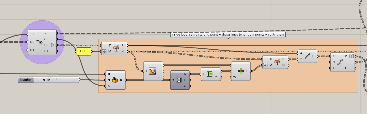
This group contains the iterative logic of the string art algorithm, using the Anemone plugin, it starts a loop.
Initialization (Fast Loop Start): the loop begins with a counter I and two data channels D0 and D1, which carry and update data across each iteration. The path {0} is used to initialize the data tree structure.
At each iteration, a Split Tree component extracts the current starting nail from the list of 425 points generated in the previous group. This nail serves as the origin of the thread for that iteration. A Random component, seeded and bounded by a Number slider (here set to 10), produces a random index. This index is used to select a destination nail from the circle by simulating the action of stretching a thread to a randomly chosen pin. The strategy is to generate random lines and then see which one fits the desired image best.
A Line component connects the starting point to the randomly selected destination point, representing one thread segment. The line is passed into a Divide Curve component, then into a Round and Create Set to extract and clean the index data. A Split Tree component then separates the results into distinct data branches for the next iteration. The outputs are passed back through D0 and D1 into the next loop cycle, so that each iteration builds upon the previous one, progressively accumulating thread segments until the loop ends.
3. Compare lines with image & choose the darkest path
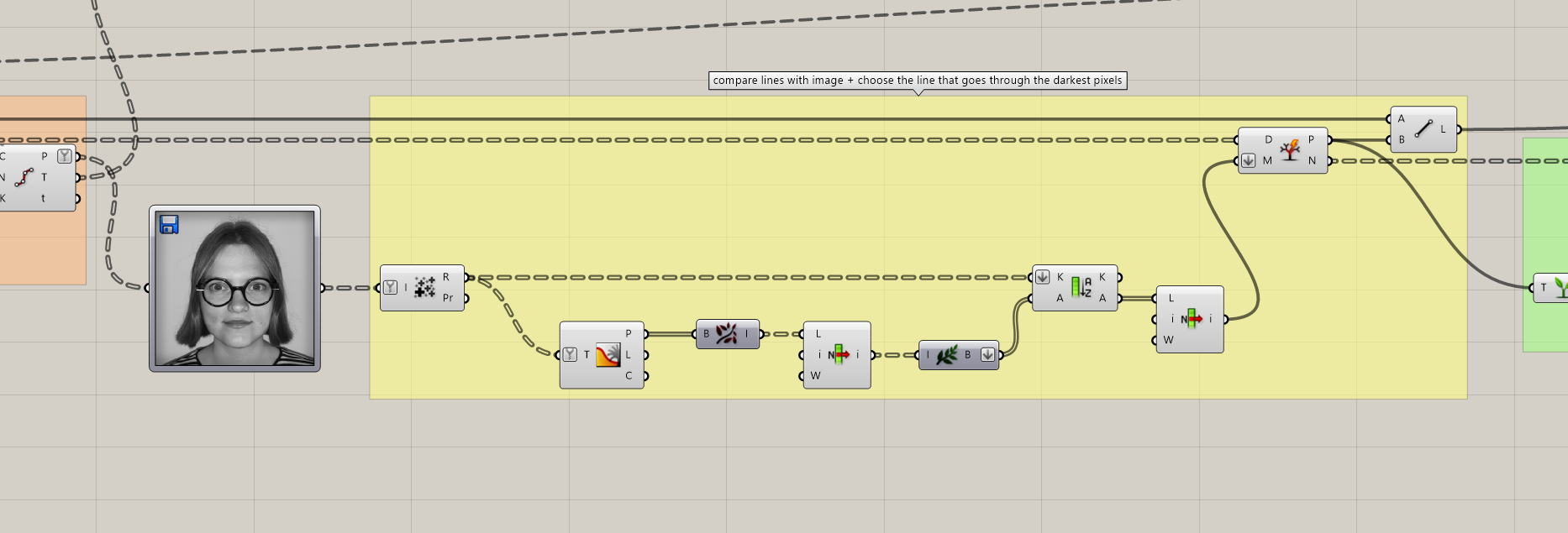
A grayscale photograph is loaded directly into the canvas, you can choose any picture you want to recreate (here is a picture of my friend). Its pixel brightness data is made available to the rest of the network.
The lines arriving from the previous group are passed into an Image Sampler, which reads the brightness values of the pixels located along each line. Darker pixels indicate areas where a thread should ideally pass. A Mass Addition accumulates the sampled brightness values per line, producing a total darkness score for each candidate. A Sort component then ranks the lines, and the one passing through the darkest pixels overall is selected via List Item. The line that best reinforces the image is passed forward through a Split Tree and Divide Curve, feeding back into the loop’s data channels for the next iteration.
In summary, this group replaces random selection with an image-driven selection: at each iteration, the script evaluates all possible thread paths and retains only the one that contributes most to reconstructing the target portrait.
4. Resets Starting Point for Next Loop
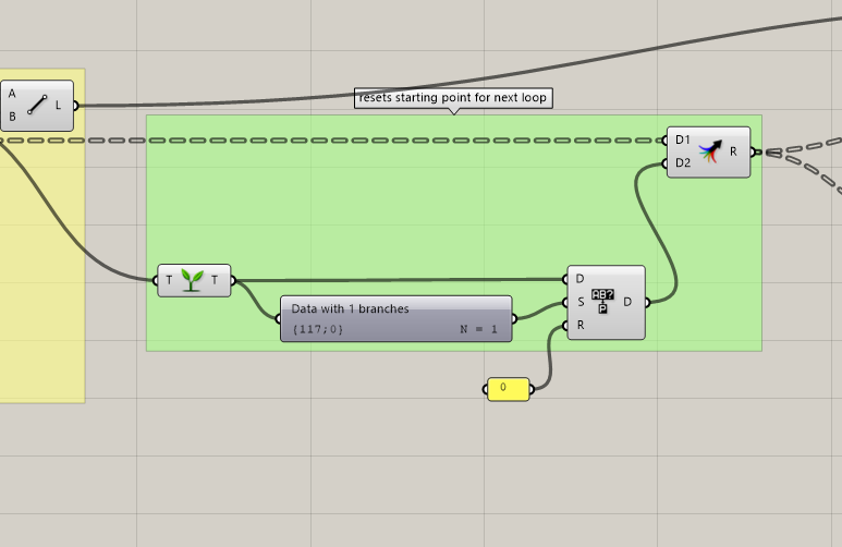
A Tree Statistics component reads the data tree coming from the selected line and extracts its structural information (specifically the path index {117;0} with N = 1), identifying which nail was used as the endpoint of the current thread.
A Create Set component processes this index, ensuring it is clean and non-redundant. The value 0 (the panel below) is used to reset or initialize the index reference. The result is passed into D1 and D2 of the Fast Loop End component (the coloured node on the right), which closes the current iteration and transmits the new starting nail position back to Fast Loop Start for the next cycle.
In summary, this group ensures that the endpoint of one thread becomes the starting point of the next, producing a continuous, connected sequence of lines.
5. Result
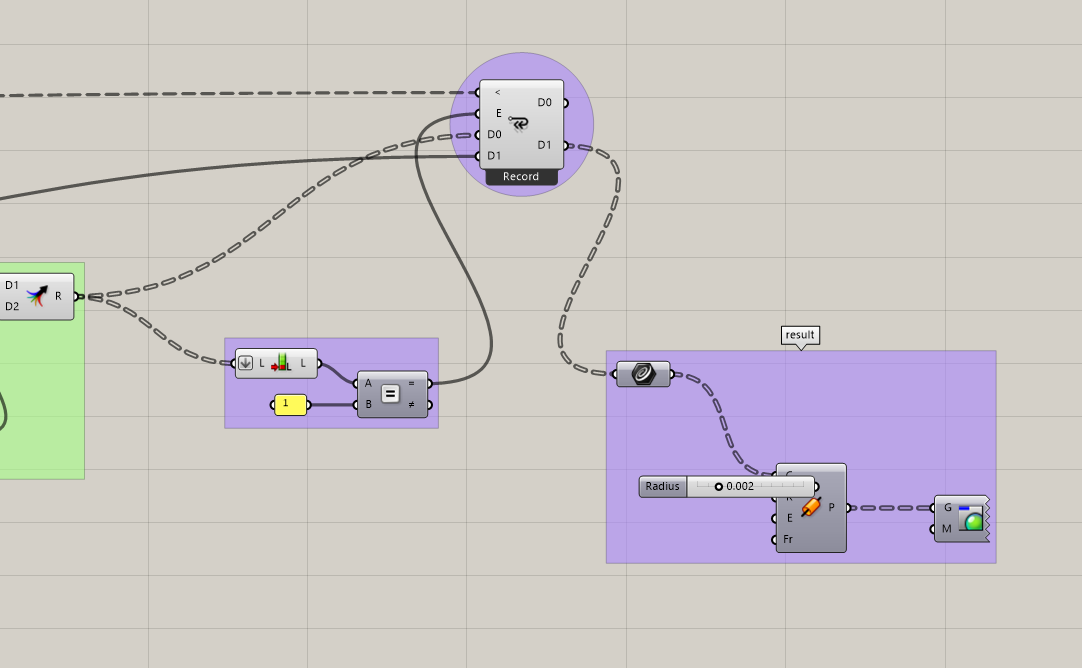
The purple Fast Loop End node receives the data channels D0 and D1 from the previous groups. The Exit (E) condition is evaluated by comparing the current line count via a List Length against the value 1 through an Equality check : once the condition is met, the loop terminates and all recorded thread segments are released as output. The collected lines exit the loop and are passed into a Curve parameter, consolidating all iterations into a single geometry set.
A Pipe component wraps each line into a thin 3D tube, using a Radius of 0.002 to simulate the thinness of an actual thread.
A Custom Preview component applies a material to the geometry, controlling its display colour in the Rhino viewport.


Here is the result with a picture of my friend.
BONUS : PLUG-IN
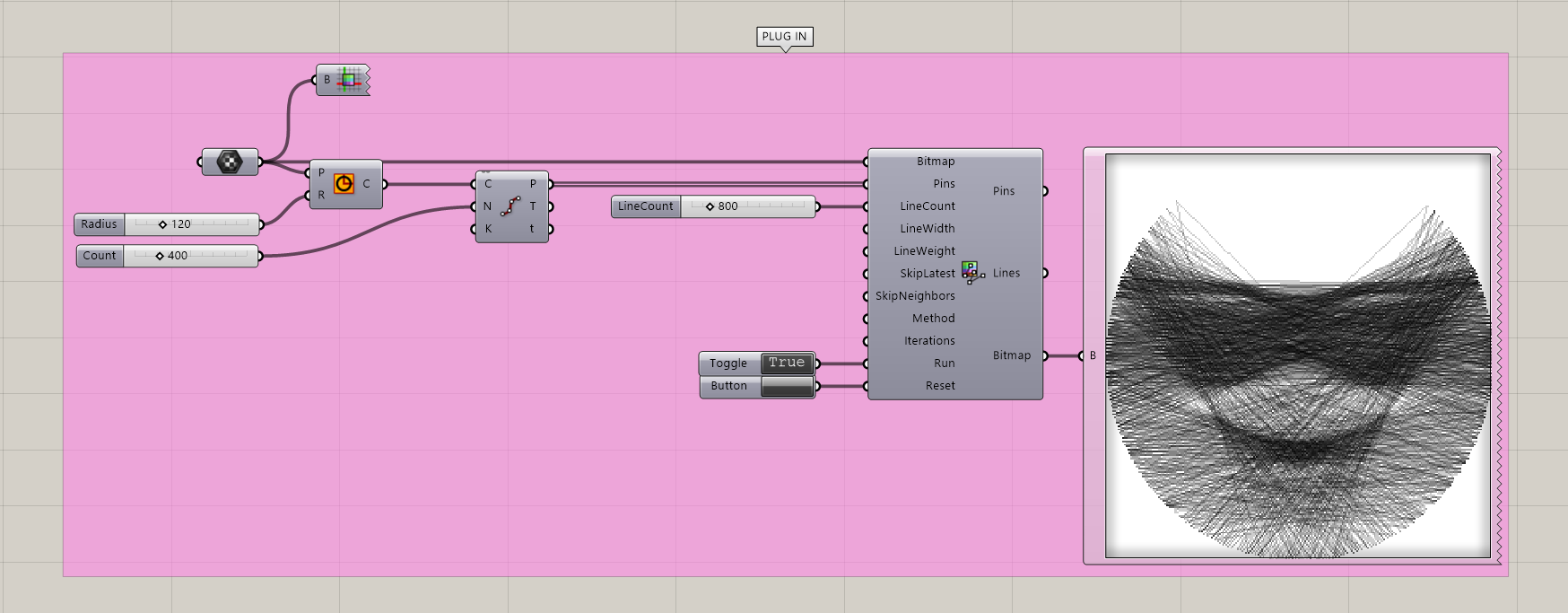
Similar results can be achieved with using a plug-in called Javid.
A circle is divided into many nail positions and fed into the Javid String Art component alongside the target image. The component autonomously computes the optimal thread sequence and outputs both the resulting line geometry and a bitmap preview, visible on the right.
PLUG-INs USED :
Anemone https://www.food4rhino.com/en/app/anemone
Javid https://www.food4rhino.com/en/app/javid
SCRIPT